KRAMER: SIMPLE CREATIVE TECHNOLOGY
Using Your FC-6801 SDI De-Embedder
8
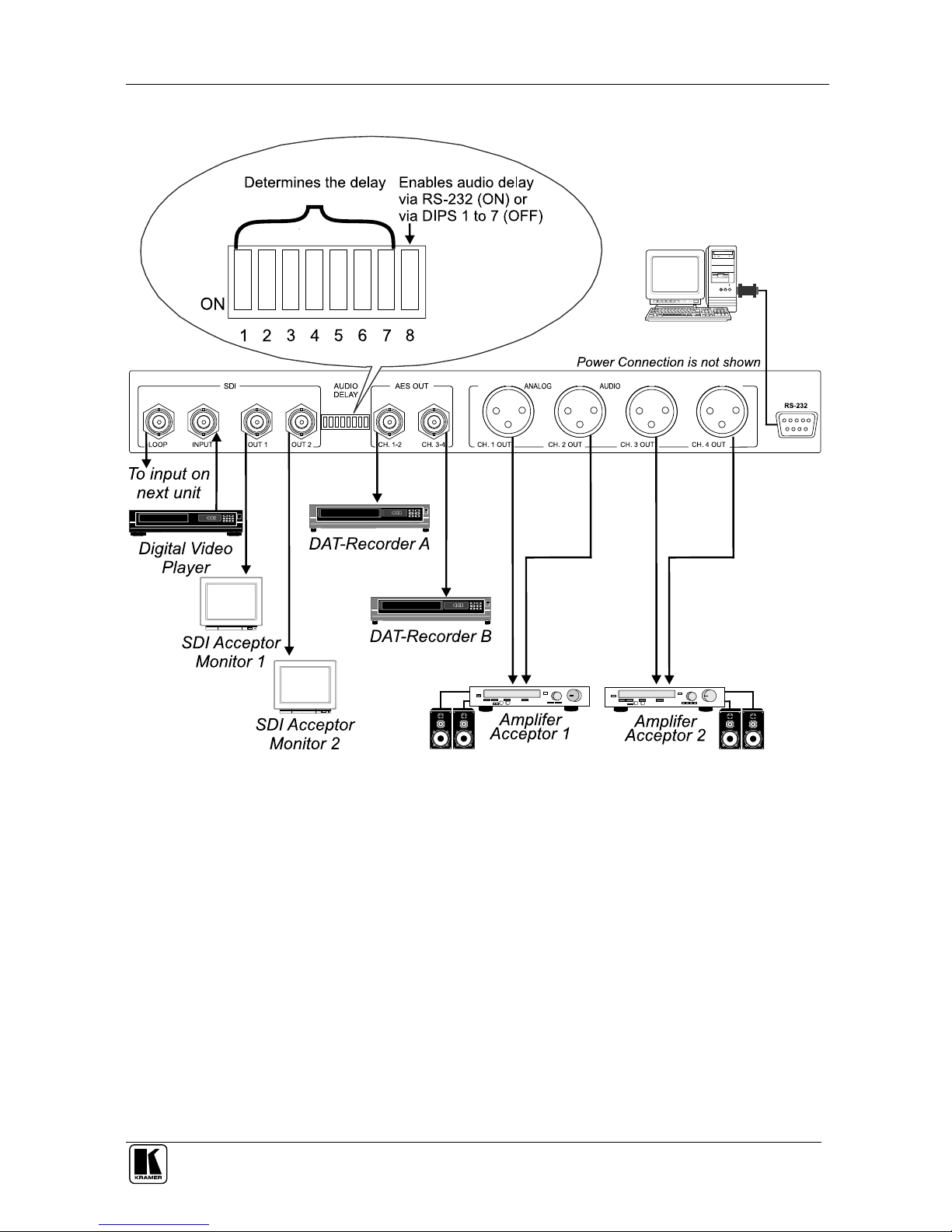
5.1.3 Cascading FC-6801 SDI De-Embedder Units
To cascade up to four FC-6801
SDI De-Embedder units, as the example in
Figure 4 illustrates, do the following
1
:
1. Connect an SDI source (for example, a digital video player) to the SDI
INPUT BNC connector on FC-6801
unit # 1 and interconnect the four
FC-6801
units:
Connect the SDI LOOP BNC connector on unit # 1 to the SDI INPUT
BNC connector on unit # 2
Connect the SDI LOOP BNC connector on unit # 2 to the SDI INPUT
BNC connector on unit # 3
Connect the SDI LOOP BNC connector on unit # 3 to the SDI INPUT
BNC connector on unit # 4
2. Connect the two AES OUT BNC connectors on each of the four FC-6801
units to eight digital audio acceptors (a total of 16 channels):
Connect the AES OUT channel 1-2 BNC connector on unit # 1 to an AES
acceptor A (channels 1 and 2), and connect the AES OUT channel 3-4 BNC
connector on unit # 1 to an AES acceptor B (channels 3 and 4)
Connect the AES OUT BNC connectors on unit # 2 to an AES acceptor C
(channels 5 and 6), and to an AES acceptor D (channels 7 and 8)
Connect the AES OUT BNC connectors on unit # 3 to an AES acceptor E
(channels 9 and 10), and to an AES acceptor F (channels 11 and 12)
Connect the AES OUT BNC connectors on unit # 4 to an AES acceptor G
(channels 13 and 14), and to an AES acceptor H (channels 15 and 16)
3. Connect the four analog audio OUT XLR connectors on each of the four
FC-6801
units to 16 analog balanced audio acceptors:
Connect the XLR connectors on unit # 1 to balanced audio acceptors 1 to 4
Connect the XLR connectors on unit # 2 to balanced audio acceptors 5 to 8
Connect the XLR connectors on unit # 3 to balanced audio acceptors 9 to 12
Connect the XLR connectors on unit # 4 to balanced audio acceptors 13 to 16
4. Connect the SDI outputs (OPTIONAL) on each of the four FC-6801
units
to up to two SDI acceptors (eight in total)
2
.
5. Connect the power cord on each of the four FC-6801
units
2
.
1 Switch OFF the power on each device before connecting it to an FC-6801 unit. After connecting each FC-6801 unit, switch
on its power and then switch on the power on each device
2 Not illustrated in Figure 4