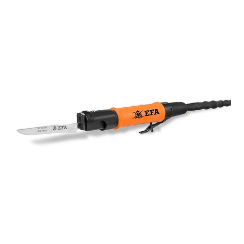
EFA 202-204 User manual

Schmid & Wezel
Execution
D 75433 Maulbronn
Page 1
01.2021
Operating instructions
Maintenance instructions
Spare part list
EFA Vacuum unit
Type EFA 202-204
Important Informations:
Please forward these operating instructions to your
operating personnel!

Schmid & Wezel
Execution
D 75433 Maulbronn
Page 2
01.2021
Table of contents
1. Use, scope of delivery, accessories ....................................................................3
1.1 Symbols in these instructions .........................................................................3
1.2 Intended use..............................................................................................3
1.2.1 Application area.....................................................................................3
1.2.2 Residual hazards....................................................................................3
2. Safety instructions .........................................................................................3
2.1 General safety instructions ............................................................................3
2.2 Behavior of the workspace ............................................................................4
3. Functional description and operation ..................................................................4
3.2 Operation ..................................................................................................5
3.2.1 Daily controls ........................................................................................5
3.2.2 Switch on.............................................................................................5
3.2.3 Switch off.............................................................................................5
3.2.4 Draining...............................................................................................5
3.2.5 Pneumatic Valve ....................................................................................5
3.2.6 Vacuum Control Valve .............................................................................5
4. Assembly.....................................................................................................6
4.1 Transport ..................................................................................................6
4.2 Before installing the Vacuum Extraction System for EFA 202 .................................6
4.3 Set up ......................................................................................................7
5. Cleaning and maintenance...............................................................................7
5.1 Receiving container......................................................................................7
5.2 Air filter.....................................................................................................7
5.3 Refill oil.....................................................................................................7
5.4 Oil change .................................................................................................8
5.5 Fan cover ..................................................................................................8
5.6 Vacuum ....................................................................................................8
5.7 Troubleshooting ..........................................................................................9
6. Take back of old equipment .............................................................................9
A. Appendix ................................................................................................... 10
A.1 Technical Data.......................................................................................... 10
A.2 Spare part list........................................................................................... 11
A.2 Schematics electrical and pneumatic .............................................................. 17

Schmid & Wezel
Execution
D 75433 Maulbronn
Page 3
01.2021
1. Use, scope of delivery,
accessories
Notes, be sure to read!
These instructions are intended for the
machine operator.
Keep the operating instructions with the
vacuum unit. It must be available at all times.
The vacuum unit may only be operated:
in technically perfect condition,
in accordance with the regulations,
as well as safety- and hazard-
conscious.
with all safety devices attached.
according to the safety instructions.
after the operating personnel have
read these instructions, in particular
chapter 2 "Safety instructions" (p.2)
and chapter 3 "Functional description
and operation" (p. 3) have been read
and understood.
This is the only way to avoid operating
errors and to assess driving situations
correctly.
1.1 Symbols in these instructions
Hazard symbol:
Extreme caution and care are
required here. In case of incorrect
behavior, there is a direct risk of
injury to the operating personnel or
third parties. In addition, the
machine may be damaged.
Information symbol:
Text passages marked with this
symbol provide you with important
information and useful tips.
1.2 Intended use
1.2.1 Application area
The vacuum unit is built according to state-of-
the-art technology and recognized safety rules.
The vacuum unit is used exclusively for the
removal of animal excrement by vacuum. Any
other use or use beyond this is considered
improper. The manufacturer is not liable.
The manufacturer is not liable for any damage
resulting from this. The risk is borne solely by
the user. Intended use also includes observing
the operating instructions and complying with
the inspection and maintenance conditions.
For all other applications, the risk of accidents
or increased wear must be pointed out. The
user alone is liable in the event of non-
compliance.
1.2.2 Residual hazards
However, the use of the equipment may result
in danger to life and limb of the user or third
parties, or damage to the equipment or other
property if the user:
is not used as intended
is improperly modified or converted
the safety instructions are not
observed
2. Safety instructions
When using the vacuum aggregate, be
sure to observe the following safety
measures.
2.1 General safety instructions
It is assumed that the operating
personnel have sufficient knowledge to
work with the vacuum unit.
Make sure that the machine is always
kept in a safe operating condition and
immediately replace defective parts
that could impair operating safety.
Installation, maintenance and repair
work may only be carried out by
authorized and qualified personnel.
Only use original EFA accessories. The
use of other tools or accessories can
be dangerous for you. Failure to use
original spare parts will void the
warranty.
Technical modifications or conversions
to the equipment are generally not
permitted and release S&W from any
warranty and liability.
The system may only be operated if all
protective and safety devices are

Schmid & Wezel
Execution
D 75433 Maulbronn
Page 4
01.2021
present and functioning properly.
The limit values for pressures and
temperatures must be permanently
marked and must not be exceeded or
fallen short of.
The warning and safety notices on the
equipment must be observed and kept
in a legible condition at all times.
2.2 Behavior of the workspace
Keep your workplace tidy. Disorder can
result in accidents.
Take environmental influences into
account. Ensure good lighting (min.
500 lux).
Always switch off the device when not
in use.
Work clothing: Do not wear loose
clothing or jewelry - these can be
caught by moving parts. Wear sturdy
shoes when working. Generally wear a
hair net!
Wear the prescribed personal hearing
protection during operation of the
system, depending on the noise level.
Avoid abnormal body posture. Ensure
secure footing and maintain balance at
all times.
When working above body height, use
suitable, safety-compliant access aids
and working platforms. Do not use any
machine parts as climbing aids.
Care for your tools with care.
Do not leave any tool keys inserted.
Before switching on, check that all
keys have been removed.
3. Functional description and
operation
Only use the vacuum unit for the
extraction of animal excrement.
3.1 Functional description
1 –Air filter
2 –Vacuum control manometer
3 –Pump
4 –Vacuum control valve
5 –Vacuum separator cut-off valve
6 –Vacuum separator ball
7 –Vacuum separator ball valve
8 –Tank
9 –Main valve
10 –Tank lock
11 –Pneumatic manual valve
12 –Main switch
The vacuum pump (3) generates a vacuum in
the receiving tank (8) and in the suction lines
directly connected to it. As a result of the
pressure compensation, the liquid flows into
the container via the suction lines. A float
switch is located in the receiving tank (8) itself.
It switches off the vacuum pump (3) when the
filling level reaches its maximum. A suction
filter (6) and an air filter (1) are connected
upstream of the vacuum pump (3). These
prevent liquid or dirt particles from entering
the vacuum pump (3). A vacuum regulating
valve (4) is used to set the vacuum. A vacuum
gauge (2) above the vacuum pump indicates
the pressure in the vessel. A sleeve valve (5) is
located at the bottom of the receiver tank (6),
through which the contents can be drained.

Schmid & Wezel
Execution
D 75433 Maulbronn
Page 5
01.2021
3.2 Operation
Only use the vacuum unit for the
extraction of animal excrement.
All cleaning agents for stainless
steel equipment are suitable for
cleaning the receptacle.
3.2.1 Daily controls
Check the air filter at least once a day
(1) for contamination and the oil level
of the vacuum pump.
The work steps are explained in the
following sections 5.2. and 5.3.
3.2.2 Switch on
Set the main switch (12) to 1.
3.2.3 Switch off
Set the main switch (12) to 0.
3.2.4 Draining
Empty the receiving container (8) when the
maximum filling level is reached and before
each longer downtime.
3.2.5 Pneumatic Valve
The pneumatic valve (7) has 2 modes
(ON / OFF).
For normal operation the pneumatic valve
should be switched ON (Upper position). When
the operator of the Vacuum Extraction System
finds that the vacuum is not temporarily
needed for operate, he can switch OFF (lower
position) the pneumatic valve.
3.2.6 VacuumControl Valve
By turning the Vacuum Control Valve (5)
clockwise You can increase vacuum (+sign on
the valve), by turning the valve anti-clockwise
(-sign on the valve) You can decrease the
vacuum.
To control the level of the vacuum look at the
manometer (6).

Schmid & Wezel
Execution
D 75433 Maulbronn
Page 6
01.2021
Emptying the receiving container:
Set the main switch (12) to 0.
Open the sleeve slide (10) at the
bottom of the receptacle (9).
After emptying, close the sleeve
slide (10).
Drain the suction filter:
Unscrew the drain valve (7) at the
bottom of the Suction filter (8).
Drain the water with the dirt residues
from the suction filter (8) out of the
suction filter (8).
Screw the drain valve (7) back in
again.
4. Assembly
4.1 Transport
It is strictly forbidden to stand
underneath a lifted load! Falling
loads can cause extremely serious
injuries.
Only transport the vacuum unit bolted
to a pallet while it is upright.
Only use suitable means of transport
and lifting gear with sufficient load-
bearing capacity.
Only use load-bearing and stable
loading ramps.
Secure the vacuum unit against sliding
and tipping.
4.2 Before installing the Vacuum
Extraction System for EFA 202
Unpack the device and assemble it, as shown
on the picture below. Use the enclosed screws
for this and tighten them with a force of
12Nm.
Connect the hose (3) and secure it with the
enclosed clamps.
Connect the EFA 202 with the tank of Vacuum
Extraction System (1) with appropriate
couplings (tank side 1") and a hose.
Before use Vacuum Extraction System, start
the vacuum pump and check the rotation of
the motor. The right direction is shown on the
housing of the pump (see arrow).
In case if the direction of the rotation of motor
is opposite side than shown on the housing of
the pump, stop the pump immediately and
change the direction by switching the two

Schmid & Wezel
Execution
D 75433 Maulbronn
Page 7
01.2021
phases (e.g. PH1 and PH2) in the plug.
NOTICE!
This operation should be done only by
qualified electrician.
Connect the pneumatic hose to the pressure
reducer.
NOTICE!
The minimal pressure for applicable
operation of the Vacuum Extraction
System is 6 bar.
After making sure, that all connections and the
direction of the rotation of the pump are
correct, turn the main switch on. The Vacuum
Extraction System is ready to operate.
4.3 Set up
The mains connection must comply
with the regulations of the local
power supply company and be
protected by a residual current
circuit breaker
(residual current <0.03 A) and fuses
(16 A, slow-blow).
Do not lay the unit on its side.
The suction connection is designed as a spigot
with a 1" female thread. A 1/2" hose nipple is
screwed into the suction connection. 1/2" hose
nipple is screwed into the suction connection.
Carry out the set-up and installation
as follows:
Set up the vacuum unit on a level,
load-bearing floor.
Anchor the vacuum unit in the floor
using hexagonal bolts (min. 8mm
diameter).
Establish a hose connection between
the unit or the system via which the
liquid is to be aspirated and the
suction connection. To do this, attach
a sufficiently long hose to the hose
nipple using hose clamps.
Have a qualified person make the
electrical connection. The socket slide
under the receiving vessel has a 2"
internal thread to which you can
connect a drain line.
Always lay the drain line with a
downward slope from the vacuum
unit.
5. Cleaning and maintenance
Disconnect the vacuum unit from
the power supply before servicing
the vacuum pump. Ventilate the
vacuum pump to ambient pressure.
5.1 Receiving container
Rinse the receptacle (8) with spray water at
least every month to remove any stuck dirt.
Proceed as follows:
Set the main switch (12) to 0.
Open the sleeve slide (10) and empty
the receiving container (8).
Close the sleeve slide (10) when the
receiving container (8) is empty.
Remove the base plate from the
receiving container (8). To do this,
loosen the fastening nuts on the base
plate.
Spray the receiving container (8) from
the underside.
All cleaning agents for stainless
steel equipment are suitable for
cleaning the receptacle.
5.2 Air filter
Check the filter element in the air filter (1) at
regular intervals (at least every three months),
as follows:
Open the retaining clips on the air
filter (1) and remove the cover.
Check the air filter (1) and replace it if
necessary.
Replace the cover on the air filter (1)
and secure it with the retaining clips.
5.3 Refill oil
Use only special vacuum pump oil
according to DIN 51506, lubricating
oil group VC. For the exact
specification, refer to the table or
enclosed operating instructions for
the vacuum pump.
When the oil level is below the MIN mark on

Schmid & Wezel
Execution
D 75433 Maulbronn
Page 8
01.2021
the sight glass, add oil. Proceed as follows:
Open the oil filler plug.
Add oil until the oil level reaches the
MAX mark on the oil sight glass.
Close the oil filler plug.
5.4 Oil change
Change the oil:
after the first 100 hours of operation.
after every further 500 ... 2000
operating hours.
Dispose of the used oil in
accordance with the applicable
regulations.
Unscrew the oil drain plug (5) on the
vacuum pump (2) and allow the used
oil to run into a collecting pan. 2.
Screw the oil drain plug (5) back in. 3.
Unscrew the oil filler plug (3) on the
vacuum pump (2) and fill in new
vacuum pump oil. 4.
Screw the oil filler plug (3) back in.
Recommended oil
types
Ambient
temperature
VM 032
< 0 °C
VM 068
0 ... 12 °C
VM 100
12 ... 30 °C
VS 100
> 30 °C
The vacuum unit contains approx. 1 l of oil.
5.5 Fan cover
Check the fan guards of the vacuum pump for
dirt. If necessary, blow out the fan guards with
compressed air.
For further maintenance
instructions, refer to the enclosed
operating instructions for the
vacuum pump.
5.6 Vacuum
Set the vacuum via the vacuum regulating
valve (15) as follows:
By turning the Vacuum Control Valve (5)
clockwise You can increase vacuum (+sign on
the valve), by turning the valve anti-clockwise
(-sign on the valve) You can decrease the
vacuum.
To control the level of the vacuum look at the
manometer (6).
The vacuum must not exceed
75 kPa! Higher negative pressures
can cause damage to the receiving
container.

Schmid & Wezel
Execution
D 75433 Maulbronn
Page 9
01.2021
5.7 Troubleshooting
Malfunction
Possible reason
Remediation
Vacuum unit does not run
Level control indicator is
out
Power supply interrupted.
Check the mains connection
and fuses. Notify the customer
service if none of the above
errors are present.
Motor protection tripped due to
overload of vacuum pump (3).
Open the switch box (12) and
check whether the motor
protection switch has tripped.
Suction filter (6) clogged and
air filter (1) wet. -> Vacuum
pump has sucked in water.
Notify customer service.
Suction filter (6) clogged.
Empty the suction filter (6)
(section 3.2).
Press the "Reset" button on the
motor protection switch.
Vacuum unit does not run
Level indicator is on
Receptacle (8) is full.
Empty the receiving container
(8) (section 3.2).
Low flow rate
Intake filter clogged
Clean/renew intake filter
Vacuum too high
Suction filter (6) clogged.
Drain the suction filter (6)
(section 3.2).
Regulating valve (4) set
incorrectly.
Readjust the vacuum
(section 5.6).
Vacuum too low
Sleeve gate valve (10) open or
not properly closed.
Close the sleeve slider (10)
Hose line at suction connection
leaking.
Check the hose line and the
devices connected to it.
Eliminate the leaks.
If necessary, replace the
leaking parts.
Regulating valve (4) set
incorrectly.
Readjust the vacuum
(section 5.6).
Leakage at the receiver (8) or
other parts of the vacuum unit.
Defective vacuum pump (3).
Notify customer service.
6. Take back of old equipment
Return old equipment to the parent company for disposal.

Schmid & Wezel
Execution
D 75433 Maulbronn
Page 10
01.2021
A. Appendix
A.1 Technical Data
Description
Value
Voltage
3 x 400 V /50 Hz / N / PE
Current
3,2A
Rated power
0,75kW
Flow rate
25 m3/h
Contents of the receptacle
90 L
Mass (net)
115 kg
Ambient temperature
+5°C - +35°C

Schmid & Wezel
Execution
D 75433 Maulbronn
Page 11
01.2021
A.2 Spare part list

Schmid & Wezel
Execution
D 75433 Maulbronn
Page 12
01.2021

Schmid & Wezel
Execution
D 75433 Maulbronn
Page 13
01.2021

Schmid & Wezel
Execution
D 75433 Maulbronn
Page 14
01.2021

Schmid & Wezel
Execution
D 75433 Maulbronn
Page 15
01.2021

Schmid & Wezel
Execution
D 75433 Maulbronn
Page 16
01.2021
Page
Part number
Part
Index
11
1
Tank
2
Vacuum separator
3
Hose
Z084015
8
Pneumatic hose
Z084194
9
Pneumatic hose
Z084194
12
7
Pneumatic manual valve
Z083927
9
Pneumatic exhaust filter
Z084193
12
5
Vacuum control valve
Z093583
6
Vacuum manometer
Z093543
13
2
Vacuum pump
Z084014
5
Main switch
Z084018
7
Pneumatic manual valve
Z083927
9
Pneumatic exhaust filter
Z084193
11
Pneumatic manometer
Z084195
12
Hose
Z084016
13
Pump filter
26 - 27
Pneumatic hoses
Z084194
29
Pneumatic hose
Z084194
34
Vacuum control unit
Z093583+
Z093543
35
Electrical box –OPTION
36
Pneumatic tee
Z013998
37
Pneumatic hose
Z084194
38
Pneumatic hose
Z084194
14
5
Vacuum separator cut-off valve
Z083809
7
Vacuum separator ball valve
Z083850
9
Vacuum separator ball
Z084022
15
4
Tank lock
Z083847
2
Tank gasket
Z084044
16
Main valve - OPTION

Schmid & Wezel
Execution
D 75433 Maulbronn
Page 17
01.2021
A.2 Schematics electrical and pneumatic

Schmid & Wezel
Execution
D 75433 Maulbronn
Page 18
01.2021
Chorzów, 19.01.2021
DECLARATION OF CONFORMITY
2006/42/EC MACHINERY
Manufacturer: Weindich Sp. J., ul. Adamieckiego 8, 41-503 Chorzów
Declare that the product described below is in conformity with the relevant provisions
of the following directives and the National Laws and Regulations adopting these
directives.
Machinery Directive: 2006/42/EC
Low Voltage Directive: 2014/35/EC
EMC Directive: 2014/30/EU
Product type: Vacuum Extraction System
Model: W0279.23.06.20
Serial Number: W0279.23.06.20 No. 001
The product has been tested and assessed by application of the following standards
or specifications. Together with all relevant National Technical Standards and
Specifications as applicable.
Applied standards:
DIN EN ISO 12100:2012
DIN EN ISO 13850:2016-03
EN 60204-1:2018-12
EN 60529:2003
EN 1672-2+A1:2009
EN 55014-1:2017-06/A11:2020-07
EN 55014-2:2015-06
DIN EN 61000-6-3:2008/A1:2012
DIN EN 61000-6-4:2019-12
Head of Technical department
Board member
Table of contents
Other EFA Industrial Equipment manuals
