efacec EFAPOWER EV HC G3 User manual

EFAPOWER
EV HC G3
HOME CHARGING STATION
Installation and User Manual

E F A P O W E R EV- H C - I N S T A L L A T I O N A N D U S E R M A N U A L
ii
Copyright and trademarks
©2014 EFACEC. All rights reserved. This material is protected by the copyright laws of Portugal and other
countries. It may not be modified, reproduced or distributed without the prior, express written consent of
EFACEC. All other products or services mentioned are the trademarks, service marks, registered trademarks or
registered service marks of their respective owners.
Symbols Index
The following symbols are used in this manual to prevent accidents which may occur as a result of incorrect use
of the charger.
Note
Read the notes carefully to ensure safe and proper use
Warning or safety observation
Read the instructions carefully to ensure safe and proper use
Risk of electric shock
Read the instructions carefully to ensure safe and proper use
Rua Eng. º Frederico Ulrich - Apartado 3078
4471-907 MOREIRA MAIA - PORTUGAL
Tel: (+351) 229403241 - Fax: (+351) 229403209
service[email protected]
www.electricmobility.efacec.com

E F A P O W E R EV- H C - I N S T A L L A T I O N A N D U S E R M A N U A L
iii
TABLE OF CONTENTS
1GENERAL PRODUCT DESCRIPTION............................................................................... 2
2GENERAL CHARACTERISTICS ....................................................................................... 3
2.1 TECHNICAL CHARACTERISTICS .......................................................................................................... 3
2.2 STANDARDS.................................................................................................................................. 4
3PRODUCT PARTS PRESENTATION ................................................................................ 5
4IMPORTANT SAFETY INSTRUCTIONS ........................................................................... 6
5INSTALLATION ............................................................................................................ 7
5.1 ENVIRONMENTAL REQUIREMENTS .................................................................................................... 7
5.1.1 Local Conditions ................................................................................................................................................... 7
5.1.2 Site Verification and Inspection............................................................................................................................ 8
5.2 SITE PREPARATION......................................................................................................................... 9
5.2.1 Upstream Wiring Information .............................................................................................................................. 9
5.2.2 Surface Preparation............................................................................................................................................ 10
5.2.3 Resources for Installation ................................................................................................................................... 10
5.2.4 Site Verification and Inspection.......................................................................................................................... 10
5.3 HANDLING AND PLACING .............................................................................................................. 11
5.3.1 Packaging........................................................................................................................................................... 11
5.3.2 Visual Inspection................................................................................................................................................. 11
5.3.3 Handling ............................................................................................................................................................. 11
5.3.4 Placing................................................................................................................................................................ 12
6START-UP ..................................................................................................................19
6.1 VERIFICATION AND INSPECTION...................................................................................................... 19
6.2 SWITCH ON................................................................................................................................ 19
7USER MANUAL ..........................................................................................................21
7.1 OUTPUT CONNECTOR ................................................................................................................... 21
7.1.1 Type 1 Connector................................................................................................................................................ 21
7.1.2 Type 2 Connector................................................................................................................................................ 21
7.1.3 Type GB Connector ............................................................................................................................................. 21
7.1.4 Type 2 outlet....................................................................................................................................................... 22
7.2 OPERATION ................................................................................................................................ 22
7.2.1 Operation Sequences (for EV-HC without Authentication) ................................................................................. 22
7.2.2 Operation Sequences (for EV-HC with Authentication) ...................................................................................... 24
8MAINTENANCE MANUAL ...........................................................................................25
8.1 PREVENTIVE MAINTENANCE .......................................................................................................... 25
8.2 TROUBLESHOOTING ..................................................................................................................... 26
E F A P O W E R EV- H C - I N S T A L L A T I O N A N D U S E R M A N U A L
1 | 28
The information presented in this guide is subject to change without prior notice.
The technical specifications indicated here do not constitute a contractual obligation.
No part of this document may be photocopied, reproduced or translated to other language without the written
consent from EFACEC.
In case of any doubt regarding a subject described in this manual, please contact us at:
Rua Eng. º Frederico Ulrich - Apartado 3078
4471-907 MOREIRA MAIA - PORTUGAL
Tel: (+351) 229403241 - Fax: (+351) 229403209
service[email protected]
www.electricmobility.efacec.com

E F A P O W E R EV- H C - I N S T A L L A T I O N A N D U S E R M A N U A L
2 | 28
1GENERAL PRODUCT DESCRIPTION
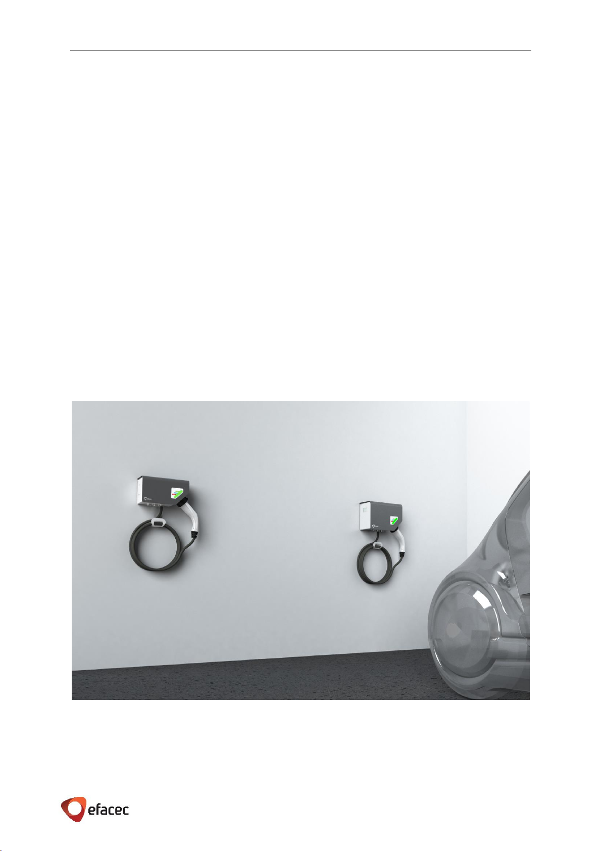
EFAPOWER EV-Home Charger (HC) station is able to charge all electric vehicles compliant with AC charging
system standards.
The battery charging cycle finishes by itself or can be interrupted by user command.
EFAPOWER EV-HC consists on a Charging Station with one output.
Are available the following AC outputs: 3,7kVA; 7,4kVA; 11kVA and
22kVA.
EFAPOWER EV-HC station is user friendly and safe. Different models
are available, with power plug or socket. When equipped with a
socket, the power cord plug is coupled into it in the charger bay.
There is a locking mechanism on the socket that prevents the user
from disconnecting the power cord during the charging process,
without first interrupt the charging process on the system or on the
vehicle. The charger has a color warning light which shows its own
operation status.
EFAPOWER EV-Home Charger station codification and configurations are presented in chapter 3.
Figure 1 - EFAPOWER EV-HC
E F A P O W E R EV- H C - I N S T A L L A T I O N A N D U S E R M A N U A L
3 | 28
2GENERAL CHARACTERISTICS
2.1 TECHNICAL CHARACTERISTICS
EFAPOWER EV-HC station technical characteristics are indicated in Table 1.
Table 1 –EFAPOWER EV-HC Technical Characteristics
Central Command Unit
User Interface
User Identification
(optional)
Contactless RFID Card (Mifare) ISO14443
Outputs
CE and GB Units
Nominal Input
Phases/Lines
1 line + neutral + earth
3 line + neutral + earth
Voltage
(230 ± 10%) Vac
(400 ± 10%) Vac
Current
16 A
32 A
16 A
32 A
Power
3,7 kVA
7,4 kVA
11 kVA
22 kVA
Frequency
(50 ± 10%) Hz
Output
Connector
CE Units: Type 1 according to EN 62196-1
CE Units: Type 2 according to EN 62196-2
GB Units: Mode 3 according with
GB/T20234.2
CE Units: Type 2 according to EN 62196-2
GB Units: Mode 3 according with
GB/T20234.2
EV Connection to EVSE
CE units: EN 61851-1 and IEC 61851-1 Case B and IEC 61851-1 Case C
GB units: GB/T 18487.1 Case C
Outlet Protection
Over-current (not
included)
20 A
40 A
20 A
40 A
RCD
30 mA
Charging Mode
Direct connection
between the EV and the
EVSE using the cable
supplied with the vehicle.
CE units: EN 61851-1 e IEC 61851-1 Mode 3
GB units: GB/T 18487.1 Mode 3
Energy metering
(optional)
Yes
Mechanical
Characteristics
Dimensions(WxDxH) mm
300x156x169 mm
320x156x224 mm
Architecture
Standalone box equipped with one output
Weight
from 4kg to 7kg (depending on the output)
Environmental
conditions
Degree of protection
IP 54
Temperature
Natural cooling (Range -30˚C to +50˚C)
Humidity
Range 5% to 95%
Installation site
Outdoor/Indoor
Specifications are subject to change, without prior notice.

E F A P O W E R EV- H C - I N S T A L L A T I O N A N D U S E R M A N U A L
4 | 28
2.2 STANDARDS
The EFAPOWER EV-Public Charger station complies with the following standards:
Table 2 –EFAPOWER EV-HC Applicable Standards
1
2006/95/CE: Low Voltage Directive
2
2004/108/CE: EMC directive
3
EN/IEC 61851-1: Electric vehicle conductive charging system. Part 1: General Requirements
4
IEC 62196: Plugs, socket-outlets, vehicle connectors and vehicle inlets - Conductive charging of electric vehicles
5
GB 156-2007: Standard Voltage
6
GB/T 18487.1: Electric vehicle conductive charging system. Part 1: General Requirements
7
GB/T 20234: Connection Set of Conductive Charging for Electric Vehicles
8
GB/T 18487.3: Electric vehicle conductive charging system. AC/DC Electric Vehicle Charging Station
9
EN/IEC 61851-22: Electric vehicle conductive charging system. Part 22: AC Electric Vehicle Charging Station
10
EN/IEC 61000-6-1: Electromagnetic compatibility (EMC). Part 6-1: Generic standards - Immunity for residential,
commercial and light-industrial environments
11
EN/IEC 61000-6-3: Electromagnetic compatibility (EMC). Part 6-3: Generic standards - Emission standard for
residential, commercial and light-industrial environments
12
GB/T 17626: Electromagnetic compatibility –Immunity to Disturbance (GB/T 17626.2; GB/T 17626.3; GB/T
17626.4; GB/T 17626.5; GB/T 17626.6; GB/T 17626.11)
13
GB 4824: Industrial, scientific and medical (ISM) radio-frequency equipment. Disturbance characteristics. Limits
and methods of measurement.
Technical Data
CE
GB
Applicable
Directives /
Standards
Universal:
2006/95/CE1
2004/108/CE2
EN/IEC 61851-13
IEC 621964
GB 156-20075
GB/T 18487.16
GB/T 202347
GB/T 18487.38
AC Charging System:
EN/IEC 61851-229
EN/IEC 61000-6-110
EN/IEC 61000-6-311
EV-READY
GB/T 1762612
GB 482413
EV-READY

E F A P O W E R EV- H C - I N S T A L L A T I O N A N D U S E R M A N U A L
5 | 28
3PRODUCT PARTS PRESENTATION
EFAPOWER EV-HC is composed by a standalone box with one output. Its codification is presented below.
EFAPOWER EV-HC has two boxes depending on the power rate. For 3,7kVA and 7,4kVA the box is represented
in Figure 3.
CE marked units can be supplied with socket or cable and GB marked units are supplied only with cable.
In Figure 4 is presented the box for 11kVA and 22kVA.
Figure 2 - EFAPOWER EV-HC Codes
Figure 3 - EFAPOWER EV-HC 3 / 7 Parts
RFID (if applicable)
Output connection
(3,7kVA –7,4kVA)
Output
signaling
Meter (if applicable)
RCD and
CB (if applicable)
left side
front side
EV-XX G3 YY 0F-00-G-KK ZZP
ZZ
Meter
MS
Simple Meter
--
wo Meter
P
Card Reader
C
RFID
--
wo Card Reader
0F
Number of Phases
1F
One-phase
3F
Three-phase
00
Current
16
16 A
32
32 A
G
Plug/Socket
P
Plug
S
Socket
KK
Mode
T2
Type T2
GB
Type GB
Home Charger 3kW –
HC3
Home Charger 7kW –
HC7
Home Charger 11kW –
HC11
Home Charger 22kW –
HC22
Figure 4 - EFAPOWER EV-HC 11 / 22 Parts
RFID (if applicable)
Output connection
(11kVA –22kVA)
Output
signaling
Meter
(if applicable)
left side
front side
RCD and
CB (if applicable)
bottom side
CE European markets
GB China market

E F A P O W E R EV- H C - I N S T A L L A T I O N A N D U S E R M A N U A L
6 | 28
4IMPORTANT SAFETY INSTRUCTIONS
SAVE THESE INSTRUCTIONS
This manual contains important instructions that must be followed during installation of the EFAPOWER EV-HC
Station.
Grounding instructions
The EFAPOWER EV-HC Station must be connected to a grounded, metal, permanent wiring system; or an
equipment-grounding conductor is to be run with circuit conductors and connected to the equipment grounding
terminal or lead on the Electric Vehicle Supply Equipment (EVSE). Connections to the EVSE shall comply with all
local codes and ordinances.
Safety and compliance
This document provides instructions to install the EFAPOWER EV-HC Station and should not be used for any other
product. Before installing the EFAPOWER EV-HC Station, you should review this manual carefully and consult
with a licensed contractor, licensed electrician and trained installation expert to ensure compliance with local
building practices, climate conditions, safety standards, and state and local codes. The EFAPOWER EV-HC Station
should be installed only by a licensed contractor and a licensed electrician and in accordance with all local and
national codes and standards. The EFAPOWER EV-HC Station should be inspected by a qualified installer prior to
the initial use. Under no circumstances will compliance with the information in this manual relieve the user of
his/her responsibility to comply with all applicable codes or safety standards. This document describes the most
commonly-used installation and mounting scenarios. If situations arise in which it is not possible to perform an
installation following the procedures provided in this document, contact EFACEC. EFACEC is not responsible for
any damages that may occur resulting from custom installations that are not described in this document.
No accuracy guarantee
Reasonable effort was made to ensure that the specifications and other information in this manual are accurate
and complete at the time of its publication. However, the specifications and other information in this manual are
subject to change at any time without prior notice.
Warranty information and disclaimer
Your use of, or modification to, the EFAPOWER EV-HC Station in a manner in which the EFAPOWER EV-HC Station
is not intended to be used or modified will void the limited warranty. Other than any such limited warranty, the
EFACEC products are provided “AS IS,” and EFACEC and its distributors expressly disclaim all implied warranties,
including any warranty of design, merchantability, fitness for a particular purposes and non-infringement, to the
maximum extent permitted by law.
Limitation of liability
IN NO EVENT SHALL EFACEC OR ITS AUTHORIZED DISTRIBUTORS BE LIABLE FOR ANY INDIRECT, INCIDENTAL,
SPECIAL, PUNITIVE, OR CONSEQUENTIAL DAMAGES, INCLUDING WITHOUT LIMITATION, LOST PROFITS, LOST
DATA, LOSS OF USE, COST OF COVER, OR LOSS OR DAMAGE TO THE EFAPOWER EV-HC STATION, ARISING OUT
OF OR RELATING TO THE USE OR INABILITY TO USE THIS MANUAL, EVEN IF EFACEC OR ITS AUTHORIZED
DISTRIBUTORS HAVE BEEN ADVISED OF THE POSSIBILITY OF SUCH DAMAGES.
E F A P O W E R EV- H C - I N S T A L L A T I O N A N D U S E R M A N U A L
7 | 28
5INSTALLATION
All matters for installing the EFAPOWER EV-HC are described in this chapter.
5.1 ENVIRONMENTAL REQUIREMENTS
EFAPOWER EV-HC Station reliability is dependent upon compliance of environmental specifications. The design
of the environmental control system for your EFAPOWER EV-HC Station, in case of extreme environmental
conditions, must ensure that the Unit can operate reliably while remaining within the range of its operating
specifications.
5.1.1 LOCAL CONDITIONS
EFAPOWER EV-HC Station has a protection degree of IP54. This Unit is intended to work below 50ᵒC ambient
temperature.
Clearance around the unit
There should be enough space to operate the unit in the front and both sides. For EV-HC 11 / 22 please ensure
also clearance in the bottom to access to the RCD.
Input Power Cables
AC input cables must be copper with appropriate power rating.
EFAPOWER EV-HC is intended to be placed on the wall, as showed in Figure 5.
Figure 5 - EFAPOWER EV-HC Station –placing
E F A P O W E R EV- H C - I N S T A L L A T I O N A N D U S E R M A N U A L
8 | 28
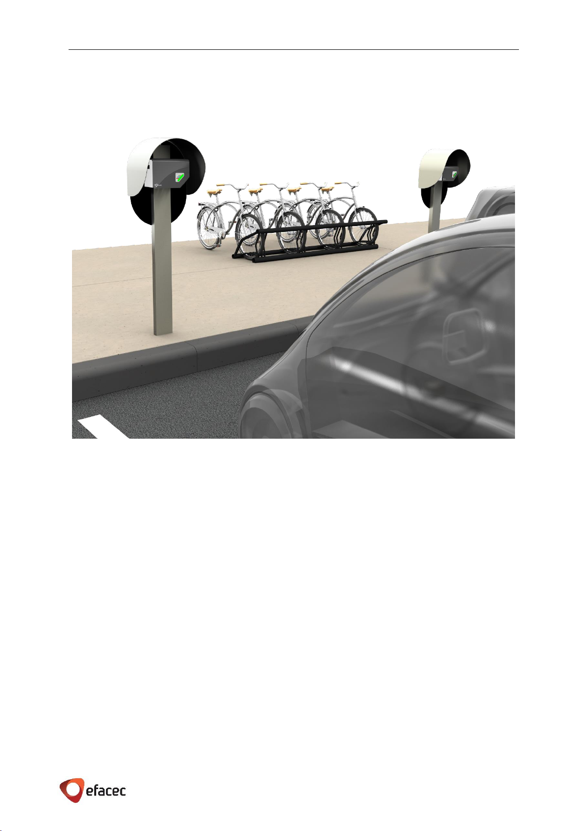
On locations with harsh weather conditions (high temperatures, heavy dust, snow and/or very low temperatures)
it’s recommended to provide additional protection, either inside a building or a shelter, or providing a roof
protection for the Unit. See example in Figure 6.
Figure 6 - EFAPOWER EV-HC with roof protection
5.1.2 SITE VERIFICATION AND INSPECTION
Check if Home Charger Station layout site is compliant with the specified clearance around the box;
E F A P O W E R EV- H C - I N S T A L L A T I O N A N D U S E R M A N U A L
9 | 28
5.2 SITE PREPARATION
Once the local conditions are verified is time to set up the site in order to be ready for the installation of the
EFAPOWER EV-HC Station.
5.2.1 UPSTREAM WIRING INFORMATION
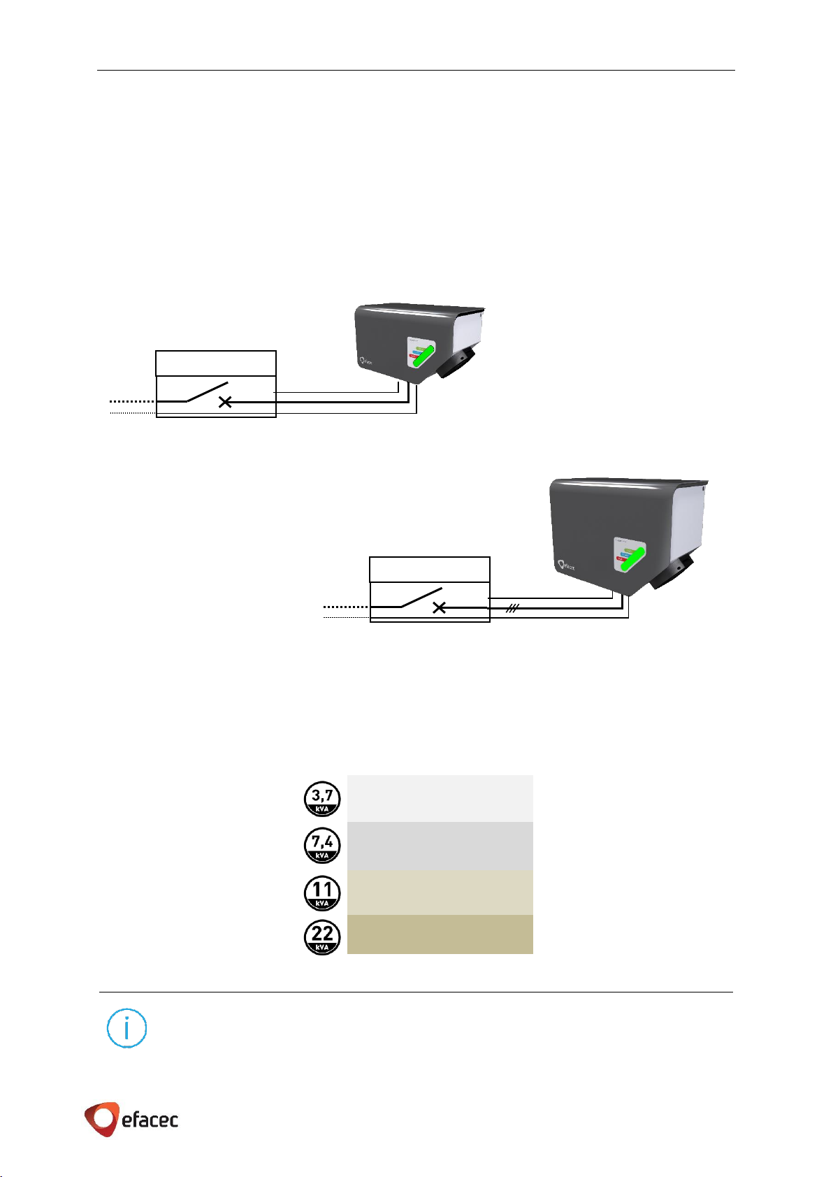
The power feeding of the EFAPOWER EV-HC with origin on the LVDB (low voltage distribution board) must be
done with dedicated wiring (line(s), neutral and earth conductors only used to supply the equipment) and
protected by a circuit breaker and a voltage suppressor, please refer Figure 7 and Figure 8.
Depending on the output of the Unit, we can have several scenarios for the circuit breaker to be installed in the
distribution board for each Unit. The appropriate circuit breaker is represented in Table 3.
NOTES
Unless it’s required by local code it’s not necessary to install a residual-current device (RCD) for
EFAPOWER EV-HC Station as it is already installed inside the unit.
Circuit Breaker 20A 1P C
Circuit Breaker 40A 1P C
Circuit Breaker 20A 3P C
Circuit Breaker 40A 3P C
Table 3 - Overcurrent protection upstream
Figure 7 - EFAPOWER EV-HC 3 / 7 Wiring Information
Figure 8 - EFAPOWER EV-HC 11 / 22 Wiring Information
Distribution Board
Ground
Neutral
Distribution Board
Ground
Neutral
E F A P O W E R EV- H C - I N S T A L L A T I O N A N D U S E R M A N U A L
10 | 28
5.2.2 SURFACE PREPARATION
Each Charging Station must be fixed to a pole or a wall by a fixing plate.
5.2.3 RESOURCES FOR INSTALLATION
For the installation of EFAPOWER EV-HC Station the following resources are going to be needed:
Fasteners:
3x Screws M4 + 3x matching Anchors
If EV-HC with cable, for cable holder: 2x Screw M4 + 2x matching Anchor
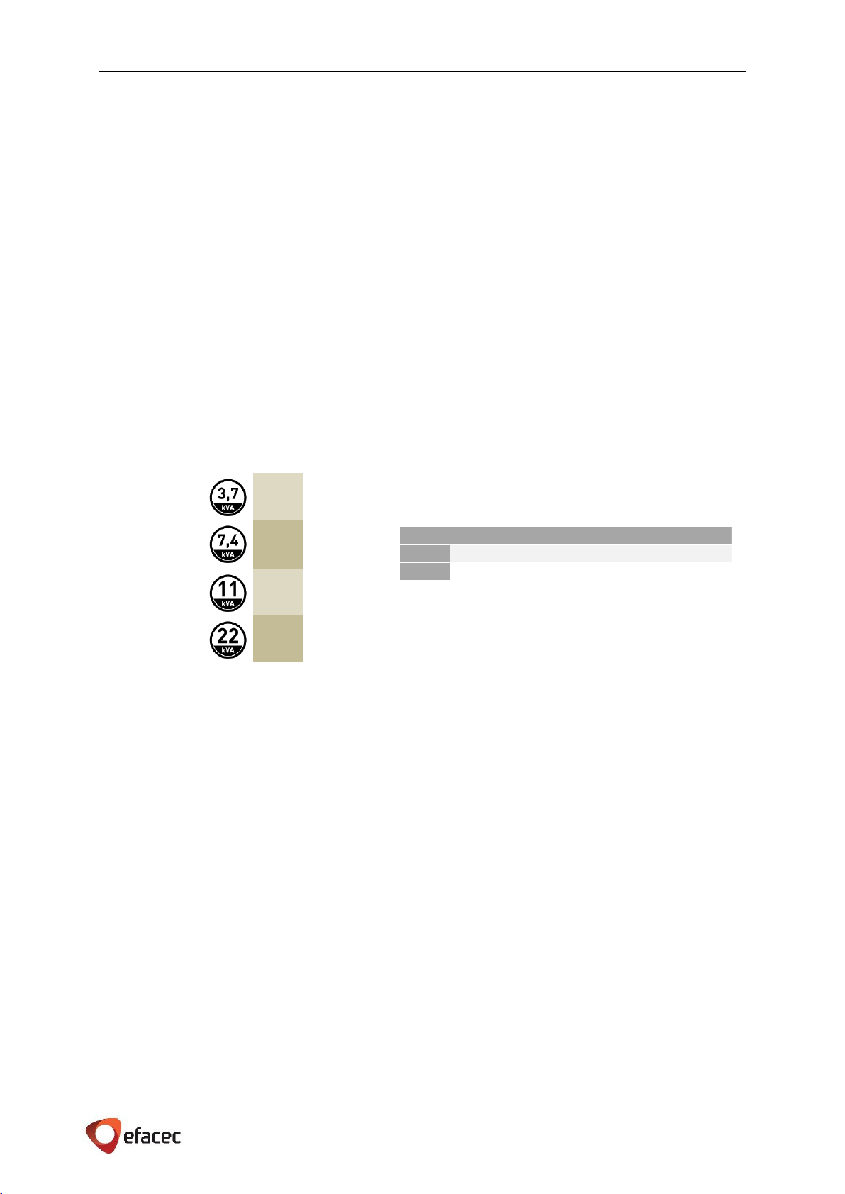
End terminals for input wiring by Unit:
EV-HC 3 / 7
3 (three) end terminals for cable according to Table 5 or according to local codes (1 phase + neutral +
protective ground)
EV-HC 11 / 22
5 (five) end terminals for cable according to Table 5 or according to local codes (3 phases + neutral +
protective ground)
16A
32A
16A
32A
Table 5 - Input lines –cross-section range
*These cross-sections are applied to copper cable length up
to 50m or according to local codes. For higher distances
contact the manufacturer.
max A
Min cross-section*
Terminal block section
16 A
2,5mm2
4mm2
32 A
4mm2
4mm2
Tools:
Screwdriver - for wall mount
Crimping tool - for power and earth cables
Torque screwdriver with flat blade - for input terminal blocks
5.2.4 SITE VERIFICATION AND INSPECTION
Check if Home Charger has the appropriate upstream protection depending on the configuration of it
Verify if the neutral is of type TT or TN. Only these two regimes guarantee a good and correct
functioning of the EFAPOWER EV-HC residual current device
Verify the earth circuit resistance: it should be according to IEC 60364/GB 16895.3, and other applicable
standards. In either case it must be under 150 Ω
Verify if the main distribution board has conditions to support one more circuit with the characteristics
required depending on the model
Execute and test the installation according to IEC 60364 standard or local regulations for CE marked
units and according to GB 16895.3, GB/T 16895.10, GB16895.5 standards or local regulations for GB
marked units
A test document will be issued by the installer responsible as a guarantee to the user that the
Homecharger was properly installed and ready to supply energy to charge the EV battery
Table 4 –Max current by phase
E F A P O W E R EV- H C - I N S T A L L A T I O N A N D U S E R M A N U A L
11 | 28
5.3 HANDLING AND PLACING
Before installing stations
The instructions provided in this manual assume that the appropriate wiring, circuit protection, and
metering are in place at the installation location.
To assist in the process of preparing the installation site, it is recommended that before you begin
installing the Charging Station, you thoroughly review the contents of this document to familiarize
yourself with the required installation steps.
In case of any doubt regarding items described in this guide, please contact us at:
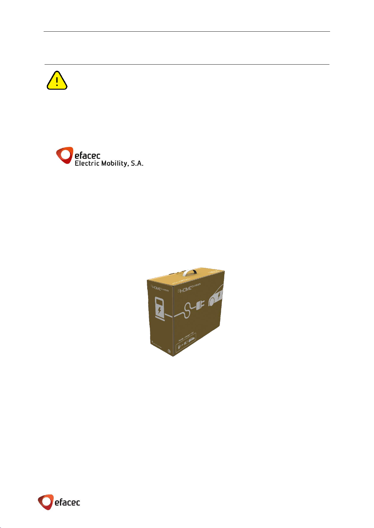
5.3.1 PACKAGING
EFAPOWER EV-HC Station is shipped in a personalized package (493x400x187mm), please refer to Figure 9. The Unit
dimension is in Technical characteristics - 2.1.
5.3.2 VISUAL INSPECTION
Check if the exterior case has been damaged by mechanical impacts or any accidents during transportation
If applicable, check if the EFAPOWER EV-HC Station decor is in perfect condition
Check for proper Unit(s) protective ground connection point, which should be interconnected with the low
voltage switchboard ground connection during the installation
5.3.3 HANDLING
Due to its weight (max 7kg), this Charging Station can be placed by one person.
Rua Eng. º Frederico Ulrich - Apartado 3078
4471-907 MOREIRA MAIA - PORTUGAL
Tel: (+351) 229403241 - Fax: (+351) 229403209
service[email protected]
www.electricmobility.efacec.com
Figure 9 - EFAPOWER EV-HC Package

E F A P O W E R EV- H C - I N S T A L L A T I O N A N D U S E R M A N U A L
12 | 28
5.3.4 PLACING
5.3.4.1 FIXING ON THE WALL
Each unit must be installed by using 3 (three) screw anchors, M4 –length must comply with local codes.
The fixation of the EV-HC should assure that no part of it is under 0,8m or above 1,5m from ground thus
permitting a comfortable handling of the equipment and charging cable.
Mounting steps:
1. Unscrew the lid
All 4 screws must be untighten to take off the lid.
2. Disconnect the lid
The lid shall not be hanging on the wires!
a. Unplug the earth cable on it (faston terminal)
b. Unplug the flat cable on the board (X14)
c. Unplug the card reader cable on the board (X6) –if applicable
3. Fix the Unit to the wall (use the drilling layout template)
In the following figures some details are shown regarding the drilling layout for both boxes.
Only 3(three) points are needed to fix each Unit on the wall (marked with a red circle) with M4 bolt.
To make easier the wall mounting, a drilling layout template, 1:1 scale, is supplied with the unit.
Additional 2(two) screws and matching anchors are need if the EV-HC has charging cable (for cable
holder).
Figure 10 - EFAPOWER EV-HC 3 / 7 Drilling Layout
Figure 11 - EFAPOWER EV-HC 11 / 22 Drilling Layout
E F A P O W E R EV- H C - I N S T A L L A T I O N A N D U S E R M A N U A L
13 | 28
4. Connect the cables
The cables entrance shall respect the place that was assigned to it at the bottom of the Unit:
EV-HC3 / EV-HC7
Left grommet –Charging Cable
(if applicable)
Middle grommet –Communications
(refer chapter 5.3.4.4)
Right grommet –Input power cables
(refer chapters 5.3.4.2 and
5.3.4.3).
EV-HC11 / EV-HC22
Left grommet –Charging Cable
(if applicable)
Middle grommet –Input power cables
(refer chapters 5.3.4.2 and
5.3.4.3).
Right grommet –Communications
(refer chapter 5.3.4.4)
5. Connect the lid
Do not forget to re-connect the cables!
a. Plug the earth cable on it (faston terminal)
b. Plug the flat cable on the board (X14)
c. Plug the card reader cable on the board (X6) –if applicable
6. Screw the lid
First, tighten all 4 screws only to the point where they are snug.
Then, tighten the screws all the way starting with the lower screws.
E F A P O W E R EV- H C - I N S T A L L A T I O N A N D U S E R M A N U A L
14 | 28
5.3.4.2 POWER CABLES CONNECTION
EVERY OPERATION ON THE EFAPOWER EV-HC MUST BE EXECUTED BY QUALIFIED PERSONNEL AND
PROPERLY AUTHORIZED. DO NOT OPERATE IN CASE OF WATER PRESENT OR HUMIDITY.
BY OPENING THE EFAPOWER EV-HC STATION’S COVERS YOU RUN RISK OF EXPOSURE TO DANGEROUS
VOLTAGES!
After unpacking and physically installing, the authorized technician must start installing the input cables.
Before connecting the EFAPOWER EV-HC must be assured:
The Grid Voltage level and frequency match the specifications on the EFAPOWER EV-HC
characteristics label
The Ground connection is connected in accordance with the harmonized standards or local regulation
The upstream protection is provided for the Unit
To ensure protection to technicians during installation of the EFAPOWER EV-HC, please verify the connections
are done according to the following conditions:
There is no input Voltage (not connected to the Grid);
No connection to Loads from the EFAPOWER EV-HC
The EFAPOWER EV-HC is OFF.
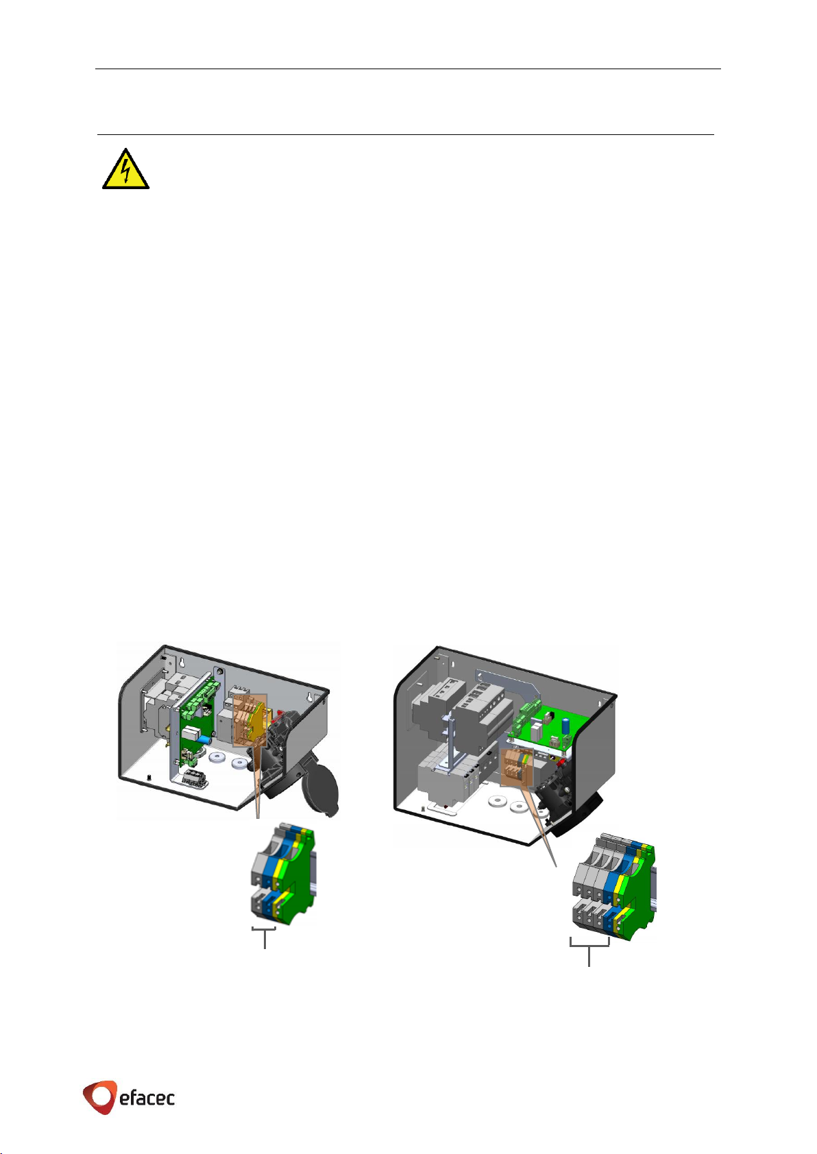
The input AC connections are done on the Charging Station as represented in Figure 12 through the grommet
mentioned below:
For 3,7kW/ 7,4kW - 1Ph+N+PE, 50/60Hz, and shall come through the right grommet
For 11kW/ 22kW - 3Ph+N+PE, 50/60Hz, and shall come through the middle grommet
Cable section of each line, depending on the power rate of EV-HC, can be consulted in Table 3 on page 9.
Figure 12 –Home Charger (front view) - Input Terminals
X1
HC 11 or HC 22
X1
HC 3 or HC 7
E F A P O W E R EV- H C - I N S T A L L A T I O N A N D U S E R M A N U A L
15 | 28
5.3.4.3 PROTECTIVE GROUND
The metallic structure is connected to the protective earth connection, as shown in Figure 13, which should be
interconnected with the low voltage switchboard earth connection.
Cable section of protective earth line, depending on the power rate of EV-HC, can be consulted in Table 3 on
page 9.
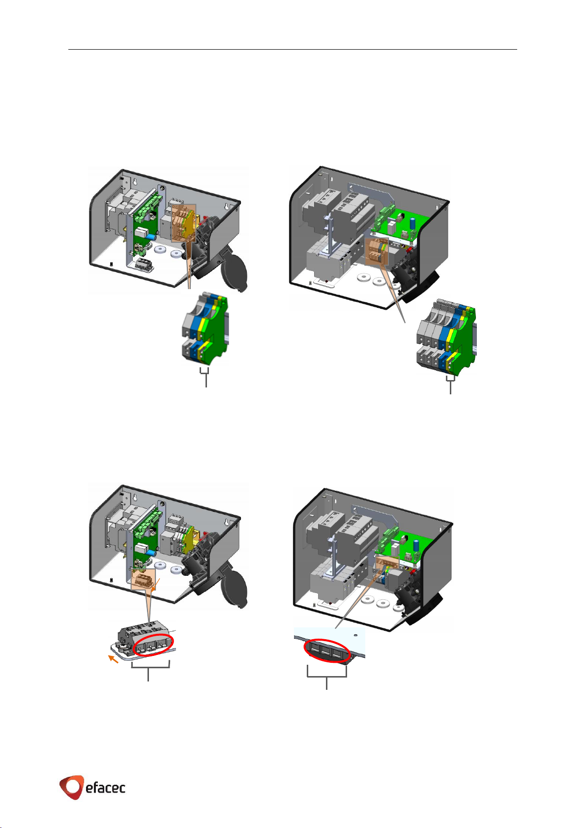
5.3.4.4 COMMUNICATIONS (IF APPLICABLE)
When applicable, the communications on the EV-HC shall be done through X2 double terminal (marked with a
red circle), represented in both EV-HC boxes on the next figure.
NOTE: The following communication scenarios are going to be represented on the one phase EV-HC box,
although they are valid also for the three phase EV-HC box.
Earth Terminal
HC 11 or HC 22
Figure 13 –Home Charger (front view) - Earth Terminals
Earth Terminal
HC 3 or HC 7
Figure 14 –Home Charger (front view) –X2 Terminals
X2 (rotated 90ᵒ)
HC 3 or HC 7
X2
HC 11 or HC 22

E F A P O W E R EV- H C - I N S T A L L A T I O N A N D U S E R M A N U A L
16 | 28
EV-HC Standalone connected to a Local PC
This scenario includes an EV-HC with RFID card reader and/or meter, with a port for communication with the PC
program Efacec Communication Manager. For more information on the Efacec Communication Manager, please
contact Efacec Electric Mobility commercial team.
If the charger isn’t equipped with an Energy Meter, the energy field on the transactions will be zero.
This communication is based on RS-485 and shall be used a USB-RS485 converter.
The Figure 16 represents the USB-RS485-WE FTDI converter.
The converter has several lines, although only 3 are needed for this communication, as referred in the following
table.
Table 6 - USB-RS485-WE FTDI converter - Connections
Cable Color
Function
X2 Terminal
Black
GND
X2.3
Orange
RS-485 D+
X2.1
Yellow
RS-485 D-
X2.2
A. Converter connected to a pre-installation outside EV-HC
If it’s not suitable the USB-RS485 converter connected directly to the EV-HC, due to distance constraints,
alternative pre-installation it’s allowed (Figure 15):
A shielded communication cable of at least 3 conductors can be connected to the EV-HC (through X2)
and end into a 3 pin panel outlet connector near a suitable place to connect the PC.
ATTENTION: This panel connector shall not be standard in order to prevent anyone to connect an
everyday use cable to the charger. USB, RJ45 adapter should not be used. This connector can also be
somehow locked to prevent inadequate use.
The mate male connector shall be assembled to the USB-RS485 FTDI converter, refer Table 6.
The panel outlet connector can now be installed in a suitable place, without length constrains, where the PC is
located. The USB-RS485 converter will link between the panel connector and the PC providing full access to the
Home Charger.
Figure 15 - Converter connected to a pre-installation outside EV-HC
Shielded communication cable of ate least
3 conductors –no length constrains
3 pin Panel Outlet Connector
USB-RS485 FTDI converter with mate
male connector

E F A P O W E R EV- H C - I N S T A L L A T I O N A N D U S E R M A N U A L
17 | 28
B. Converter directly connected to EV-HC
In this case the converter is directly connected to the X2 terminal of EV-HC, as represented in Figure 16.
The USB connection point can now be installed in a fixed location where the PC is located, providing full access
to the Home Charger.
A Network of EV-HCs connected to a Local PC
This scenario is a development of the previous. In this situation, all the chargers are connected together through
the X2 connector in Unit, and each charger is equipped with a RFID card reader and/or meter.
If the charger isn’t equipped with an Energy Meter, the energy field on the transactions will be zero.
The transactions can be saved in an excel file ant therefore reports of charge associated to a specific RFID card
can be generated.
ATTENTION: There is a Maximum limit of the number of the chargers that can be connected this way: 127
chargers in the network.
A USB-RS485 converter is used to connect all the chargers to a Local PC, refer Table 6.
The USB converter is connected between the Local PC and the first/closest charger (through X2). The pre-
installation presented above can be implemented.
Thereafter each charger is connected through the same X2 terminal till the last. A shielded communication cable
of at least 3 conductors shall be used, as represented in the following figure.
Shielded communication cable of ate least
3 conductors –no length constrains
3 pin Panel Outlet Connector
USB-RS485 FTDI
converter with
mate male
connector
Figure 17 - Network of EV-HCs connected to a local PC
Figure 16 - Converter directly connected to EV-HC
Cable length should be 5 meters
maximum
Table of contents
Other efacec Batteries Charger manuals


Popular Batteries Charger manuals by other brands


Schumacher
Schumacher SE-40225 owner's manual

Universal Power Group
Universal Power Group 12BC2000T-1 Specification sheet

Hitachi
Hitachi UC 18YGL Safety instructions and instruction manual

CS-Electronic
CS-Electronic Professional X2 Charger manual

Panasonic
Panasonic FZ-VCBN141 operating instructions

ECTIVE
ECTIVE Multiload PRO operating instructions