Motomaster ELIMINATOR 11-1586-4 User manual

TMTM
OWNER’S MANUAL
Intelligent Battery Charger
with Engine Start
011-1586-4
0099001511-00


Owner’s Manual
Suitable for all 12 V lead-acid batteries,
including deep cycle and AGM
Fully automatic • Multi-stage charging
MODEL 11-1586-4
Intelligent Battery Charger with
Engine Start
• 150 A Engine Start
• 55 A Express Charge
• 20 A Fast Charge
• 2 A Trickle Charge
BATTERY CHARGER

2TABLE OF CONTENTS
TABLE OF CONTENTS
INTRODUCTION ........................................................................................ 3
SAFETY INFORMATION
Important Safety Instructions ...................................................................... 3
Personal Safety Instructions ........................................................................ 4
AC Electrical Connections .......................................................................... 4
Preparing to Charge................................................................................. 5
Charger Location.................................................................................... 6
DC Connection Precautions ........................................................................ 6
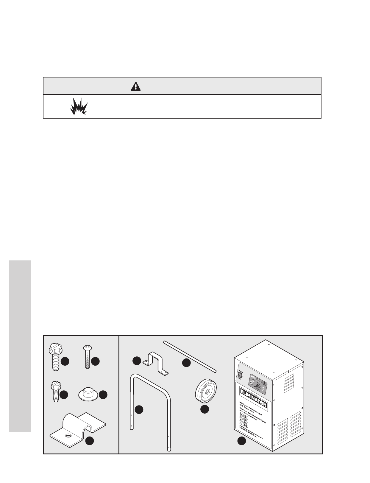
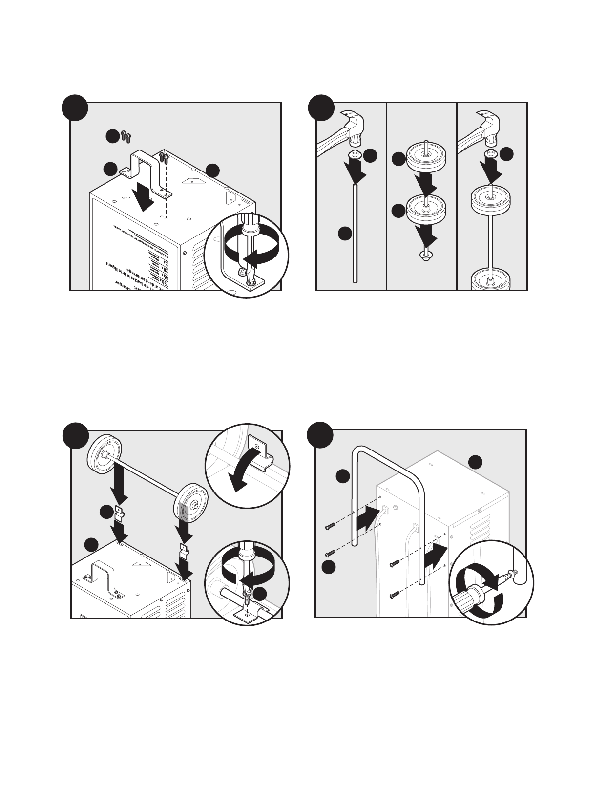
ASSEMBLY INSTRUCTIONS ............................................................................. 6
UNDERSTANDING CONTROLS & FEATURES
Function Switch ..................................................................................... 8
Charge Rate Button ................................................................................. 8
Timer Button ........................................................................................ 9
Digital Display ....................................................................................... 9
Display Mode Button .............................................................................. 9
Automatic Start Button ............................................................................. 9
CONNECTING YOUR BATTERY
Battery in Vehicle (Negative Grounded) ........................................................... 10
Battery in Vehicle (Positive Grounded)............................................................. 11
Battery Removed from Vehicle ..................................................................... 12
CHARGING YOUR BATTERY
Normal Operation .................................................................................. 13
Automatic Charging ................................................................................ 13
Hold.................................................................................................. 13
Timed Charging ..................................................................................... 14
Manual Charging.................................................................................... 14
Calculating Charge Times........................................................................... 15
OTHER LEDs & FEATURES
Battery Status LEDs ................................................................................. 16
Modes................................................................................................ 16
Voltage Tester ....................................................................................... 17
Alternator Performance Tester ..................................................................... 18
JUMP-STARTING YOUR VEHICLE
Using the Engine Start Feature..................................................................... 19
Engine Starting Notes............................................................................... 20
MOVING & STORAGE ................................................................................... 21
TROUBLESHOOTING/FAILURE CODES ................................................................. 22
MAINTENANCE AND CARE............................................................................. 25
LIMITED WARRANTY.................................................................................... 26
SAVE THESE INSTRUCTIONS
This manual contains important safety and operating instructions.
Read all instructions and follow them with the use of this product.
Questions? Call Customer Service at 1-800-528-6817 for model 011-1586-4.

3
SAFETY INFORMATION
Thank you for purchasing the MotoMaster Eliminator™ Charger. This unit can safely and easily charge,
boost and maintain all 12 V lead-acid batteries, and also function as a voltage tester and alternator
performance tester.
The purpose of this Owner’s Manual is to provide explanations and procedures on operating,
maintaining and troubleshooting the product to enable you to fully utilize the functions and features
it provides, safely and eectively.
SAFETY INFORMATION
Important Safety Instructions
• Keep out of reach of children.
• DO NOT expose the charger to rain or snow.
• Use only recommended attachments. Use of attachments not recommended or sold by
MotoMaster® may result in a risk of re, electric shock or injury to persons, or damage to property.
• To reduce the risk of damage to the electric plug or cord, pull by the plug rather than the cord
when disconnecting the charger.
• An extension cord should not be used unless absolutely necessary. Use of an improper extension
cord could result in a risk of re and electric shock. If an extension cord must be used, make sure:
– That the pins on the plug of the extension cord are the same number, size and shape as those of
the plug on the charger.
–That the extension cord is properly wired and in good electrical condition.
– T
hat the wire size is large enough for the AC ampere rating of the charger as specied on page 5.
• To reduce the risk of electric shock, unplug the charger from the outlet before attempting any
maintenance or cleaning. Simply turning o the controls will not reduce this risk.
• DO NOT operate the charger with a damaged cord or plug; have the cord or plug replaced
immediately by a qualied service person. (Call customer service at 1-800-528-6817.)
• DO NOT operate the charger if it has received a sharp blow, been dropped or otherwise damaged
in any way; take it to a qualied service person. (Call customer service at 1-800-528-6817.)
• DO NOT disassemble the charger; take it to a qualied service person when service or repair is
required. Incorrect reassembly may result in a risk of re or electric shock. (Call customer service at
1-800-528-6817.)
• WORKING IN THE VICINITY OF A LEAD-ACID BATTERY IS DANGEROUS. BATTERIES GENERATE
EXPLOSIVE GASES DURING NORMAL BATTERY OPERATION. FOR THIS REASON, IT IS OF UTMOST
IMPORTANCE THAT YOU FOLLOW THE INSTRUCTIONS EACH TIME YOU USE THE CHARGER.
• To reduce the risk of a battery explosion, follow these instructions and those published by the
battery manufacturer and the manufacturer of any equipment you intend to use in the vicinity of
the battery. Review the cautionary markings on these products and on the engine.
RISK OF ELECTRIC SHOCK OR FIRE RISK OF EXPLOSIVE GASES
WARNING
INTRODUCTION

SAFETY INFORMATION (cont’d)
4
SAFETY INFORMATION
Personal Safety Instructions
• NEVER smoke or allow a spark or ame in the vicinity of a battery or engine.
• Remove personal metal items such as rings, bracelets, necklaces and watches when working with a
lead-acid battery. A lead-acid battery can produce a short-circuit current high enough to weld a ring
or the like to metal, causing a severe burn.
• Be extra cautious to reduce the risk of dropping a metal tool onto the battery. It might spark or
short-circuit the battery or other electrical part that may cause an explosion.
• Use this charger for charging LEAD-ACID batteries only. It is not intended to supply power to a low
voltage electrical system other than in a starter-motor application. DO NOT use this battery charger
for charging dry-cell batteries that are commonly used with home appliances. These batteries may
burst and cause injury to persons and damage to property.
• NEVER charge a frozen battery.
• NEVER overcharge a battery.
• Consider having someone close enough by to come to your aid when you work near a lead-acid
battery.
• Have plenty of fresh water and soap nearby in case battery acid contacts your skin, clothing or eyes.
• Wear complete eye and body protection, including safety goggles and protective clothing. Avoid
touching your eyes while working near the battery.
• If battery acid contacts your skin or clothing, immediately wash the area with soap and water. If acid
enters your eye, immediately ood the eye with cold running water for at least 15 minutes and get
medical attention right away.
• If battery acid is accidentally swallowed, drink milk, the whites of eggs or water. DO NOT induce
vomiting. Seek medical attention immediately.
AC Electrical Connections
WARNING
RISK OF EXPLOSIVE GASES
RISK OF ELECTRIC SHOCK OR FIRE RISK OF EXPLOSIVE GASES
WARNING

• This battery charger is for use on a nominal 120 V circuit and has a 3-pronged grounded plug. The
charger must be grounded to reduce the risk of electric shock. The plug must be plugged into an
outlet that is properly installed and grounded in accordance with all local codes and ordinances. The
plug pins must t the receptacle (outlet). DO NOT use with an ungrounded system.
NOTE: Pursuant to Canadian Regulations, use of an adapter plug is not allowed in Canada. Use of an
adapter plug in the United States is not recommended and should not be used.
• Recommended minimum AWG size for extension cord:
–100 feet (30.5 metres) long or less – use a 14 gauge (2.5 mm2) extension cord.
–Over 100 feet (30.5 metres) long – use a 12 gauge (4 mm2) extension cord.
Preparing to Charge
• If it is necessary to remove the battery from the vehicle to charge it, ALWAYS remove the grounded
terminal rst. Make sure all of the accessories in the vehicle are o, to prevent arcing.
• Be sure the area around the battery is well ventilated while the battery is being charged.
• Clean the battery terminals before charging the battery. During cleaning, keep airborne corrosion
from coming into contact with your eyes, nose and mouth. Use baking soda and water to neutralize
the battery acid and help eliminate airborne corrosion. DO NOT touch your eyes, nose or mouth.
• Add distilled water to each cell until the battery acid reaches the level specied by the battery
manufacturer. DO NOT overll. For a battery without removable cell caps, such as valve regulated
lead-acid batteries (VRLA), carefully follow the manufacturer’s recharging instructions.
• Read, understand and follow all instructions for the charger, battery, vehicle and any equipment
used near the battery and charger. Study all of the battery manufacturer’s specic precautions
and recommended rates of charge while charging.
• Determine the voltage of the battery by referring to the vehicle owner’s manual and make sure that
the output voltage selector switch is set to the correct voltage. If the charger has an adjustable
charge rate, charge the battery in the lowest rate rst.
• Make sure that the charger cable clips make tight connections.
SAFETY INFORMATION (cont’d)
SAFETY INFORMATION
5
RISK OF CONTACT WITH BATTERY ACID. BATTERY ACID IS A HIGHLY
CORROSIVE SULPHURIC ACID.
WARNING
DANGER
NEVER alter the AC cord or plug provided – if it does not t the outlet, have a proper
grounded outlet installed by a qualied electrician. An improper connection
can result in a risk of electric shock or electrocution.

SAFETY INFORMATION (cont’d)
6
SAFETY INFORMATION
Charger Location
• Locate the charger as far away from the battery as the DC cables permit.
• NEVER place the charger directly above the battery being charged; gases from the battery will
corrode and damage the charger.
• DO NOT set the battery on top of the charger.
• NEVER allow battery acid to drip onto the charger when reading the electrolyte specic gravity
or lling the battery.
• DO NOT operate the charger in a closed-in area or restrict ventilation in any way.
DC Connection Precautions
• Connect and disconnect the DC output clips only after setting all of the charger switches to the
“OFF” position (if applicable) and removing the AC plug from the electrical outlet. NEVER allow the
clips to touch each other.
• Attach the clips to the battery and chassis, as shown in Connecting Your Battery.
ASSEMBLY INSTRUCTIONS
It is important to fully assemble your charger before use. Remove all cord wraps and uncoil the cables
prior to using the battery charger. Follow these instructions for assembly.
The following tools are needed for assembly: 3/8” wrench, 5/16” wrench, 1/4” wrench, hammer,
screwdriver, Phillips screwdriver.
RISK OF EXPLOSION AND CONTACT WITH BATTERY ACID.
WARNING
ASSEMBLY INSTRUCTIONS
x4
Ax4
B
x2
Cx2
D
x2
I
x2
E
F
H
J
G

ASSEMBLY INSTRUCTIONS (cont’d)
ASSEMBLY INSTRUCTIONS
7
1
2
x4 A
FJ
1
22
2
3
1
DI
I
G
D
2
Attach the Foot – Remove the charger from
the packing materials and place upside down
on a at surface. Attach the foot (1) and secure
it (2) with the four 1/4” – 20 thread cutting
screws provided.
Assemble the Wheels and Axle – Hold the
axle upright on the oor or work surface. Then,
using a hammer, tap one of the axle caps onto
the top end of the axle (1). Be sure to tap the
axle cap on straight. Slide both wheels onto the
axle (2) with the recessed hubs facing out as
shown. Install the second axle cap (3).
Mount the Axle to the Charger – Place one
end of each bracket into the slot on the bottom
of the charger (1). Place the axle assembly
under each bracket (2). Rotate the brackets
horizontally (3). Attach the brackets using the
two 10” – 32 thread cutting screws provided (4).
Attach the Handle – If the charger came with
a plastic grip, slide that onto the handle until
it is centered at the top. Turn the charger right
side up onto its foot and wheels. Align the
handle screw holes with the screw holes on the
upper back corners of the charger (1). Attach
the handle using the four Phillips head screws
provided (2).
1
2
1
2
4
3
E
J
3
C
1
1
2
x4
B
H
J
4

UNDERSTANDING CONTROLS & FEATURES
8
Controls
Function Switch
Use this switch to select between the dierent charge rates and the engine start mode.
• (O)Position:When the switch is in this position (middle), the charger is turned o.
• 20/2A– When the switch is in this position (down), the charge rate button can be set to the 2 amp
setting or the 20 amp setting. This position can also be used for testing the battery and alternator.
• 150/55A– When the switch is in this position (up), the charge rate button can be set to the 55 amp
charge rate or the 150 amp engine start setting.
Charge Rate Button
Use the charge rate button to select the charge rate or engine starting setting you require.
• 2ATrickleCharge– Intended for charging small batteries such as those commonly used in garden
tractors, snowmobiles and motorcycles. It can also be used to maintain large batteries that are
already fully charged.
• 20AFastand55AExpressCharge
Rates – Use for charging automotive,
marine and deep-cycle batteries.
• 150AEngineStart– Provides 150
amps for cranking an engine with a
weak or run-down battery. Always use
in combination
with a battery.
Timer Button
• TimerSetting– The timer allows you to set a specic time for charging. After the timer expires,
the charger stops charging your battery. The main function of the timer is to prevent overcharging
UNDERSTANDING CONTROLS & FEATURES
Function
Switch
Charge Rate
Button
Timer
Control Time
LEDs
Auto
Start
Digital
Display
Display Mode
Button
Connected (Red)
Display Mode
LEDs
Charging (Yellow)
Charged (Green)
0.1.2.
1 2.0.
1.5.0.
Charge Rate
Taux de charge
2 A
20 A/55 A
150 A

UNDERSTANDING CONTROLS & FEATURES (cont’d) 9
UNDERSTANDING CONTROLS & FEATURES
while allowing a battery time to obtain a satisfactory charge. To properly set the timer, you must
know the size of the battery in ampere hours or reserve capacity in minutes and the state of charge.
It is important that you determine the appropriate state of charge of your battery as specied. See
Calculating Charge Times and set the timer accordingly.
Digital Display
The digital display gives a digital indication of voltage, amperage or percentage of charge of the
battery, depending on the display mode chosen. The display will show the battery VOLTAGE when the
charger is not charging a battery.
Display Mode Button
Pressing the display mode button as many times as necessary allows you to cycle through the digital
displays. Stop pressing when the LED lights next to your choice. The display will show the battery
voltage when the charger is not charging a battery.
• Voltage– The digital display shows the voltage at the charger battery clips in DC volts. During
charging, the display will show 12.
• Amperage– The digital display shows the charge rate selected (2, 20 or 55) or the engine start rate (150).
• Battery%– The digital display shows an estimated charge percentage of the
battery connected to the charger battery clips.
Automatic Start Button
• Use the auto start button to start charging in automatic mode (see Charging
Your Battery).
This battery charger MUST be fully assembled in accordance
with the Assembly Instructions BEFORE it is used.
WARNING
01.2.
02.0
05.0.
Voltage/Volts
Amperage/Ampères
Charge %
% de niveau de charge
Battery %
Voltage
Amps

CONNECTING YOUR BATTERY
10
Battery in Vehicle (Negative Grounded)
++–
+
+–
4
2
3
1
A SPARK NEAR A BATTERY MAY CAUSE A BATTERY EXPLOSION.
WARNING
NOTE: A marine battery installed in a boat must be removed and charged on shore. To charge it on board
requires equipment specially designed for marine use.
1Before connecting and disconnecting the
DC output clamps, remove the AC plug from
the electrical outlet.
NEVER allow the DC output clamps
to touch each other. This may cause
a spark.
Toreducetheriskofasparknearbattery:
• Position AC and DC cords to reduce the risk of
damage by hood, door, or moving engine part.
• Stay clear of fan blades, pulleys, and other
parts that can cause injury.
• Check polarity of battery posts. A positive (POS,
P, +) battery post usually has a larger diameter
than a negative (NEG, N, –) battery post.
2 Connect the POSITIVE (RED) clip from the
battery charger to the POSITIVE (POS, P, +)
ungrounded post of the battery.
3 Connect the NEGATIVE (BLACK) clip to vehicle
chassis (must be a heavy gauge metal part of
the frame) or engine block away from battery.
DO NOT connect clip to carburetor, fuel lines,
or sheet-metal body parts.
4 Connect charger’s AC supply cord to electrical
outlet. (When disconnecting the charger,
turn the Function Switch to OFF, disconnect
the AC cord, remove the clip from the vehicle
chassis and then remove the clip from the
battery terminal.)
• See Calculating Charge Times for length of
charge information.

CONNECTING YOUR BATTERY (cont’d) 11
CONNECTING YOUR BATTERY
1Before connecting and disconnecting the
DC output clamps, remove the AC plug from
the electrical outlet.
NEVER allow the DC output clamps
to touch each other. This may cause
a spark.
Toreducetheriskofasparknearbattery:
• Position AC and DC cords to reduce the risk of
damage by hood, door, or moving engine part.
• Stay clear of fan blades, pulleys, and other
parts that can cause injury.
• Check polarity of battery posts. A positive (POS,
P, +) battery post usually has a larger diameter
than a negative (NEG, N, –) battery post.
2 Connect the NEGATIVE (NEG, BLACK) clip
from the battery charger to the NEGATIVE
(NEG, N, –) ungrounded post of the battery.
3Connect the POSITIVE (RED) clip to vehicle
chassis (must be a heavy gauge metal part of
the frame) or engine block away from battery.
DO NOT connect clip to carburetor, fuel lines,
or sheet-metal body parts.
4 Connect charger’s AC supply cord to electrical
outlet. (When disconnecting the charger,
turn the Function Switch to OFF, disconnect
the AC cord, remove the clip from the vehicle
chassis and then remove the clip from the
battery terminal.)
• See Calculating Charge Times for length of
charge information.
Battery in Vehicle (Positive Grounded)
++–
+
+–
2
3
4
1
A SPARK NEAR A BATTERY MAY CAUSE A BATTERY EXPLOSION.
WARNING
NOTE: A marine battery installed in a boat must be removed and charged on shore. To charge it on board
requires equipment specially designed for marine use.

CONNECTING YOUR BATTERY (cont’d)
12
CONNECTING YOUR BATTERY
Battery Removed from Vehicle
++
+
–
23
5
14
1Before connecting and disconnecting the
DC output clamps, remove the AC plug from
the electrical outlet.
NEVER allow the DC output clamps
to touch each other. This may cause
a spark.
Toreducetheriskofasparknearbattery:
• Check polarity of battery posts. A positive (POS,
P, +) battery post usually has a larger diameter
than a negative (NEG, N, –) battery post.
2 Attach at least a 60 cm 6-gauge (AWG)
insulated battery cable to a negative
(NEG, N, –) battery post.
3 Connect the POSITIVE (RED) clip from the
battery charger to the POSITIVE (POS, P, +)
ungrounded post of the battery.
2
4 Position yourself and the free end of cable
as far away from battery as possible, then
connect the NEGATIVE (BLACK) charger clip to
the free end of cable. DO NOT face battery
when making nal connection.
5 Connect charger’s AC supply cord to electrical
outlet. (When disconnecting the charger,
turn the Function Switch to OFF, disconnect
the AC cord, remove the clip from the vehicle
chassis and then remove the clip from the
battery terminal.)
• See Calculating Charge Times for length of
charge information.
A SPARK NEAR A BATTERY MAY CAUSE A BATTERY EXPLOSION.
WARNING
NOTE: A marine battery installed in a boat must be removed and charged on shore. To charge it on board
requires equipment specially designed for marine use.

CHARGING YOUR BATTERY
13
Normal Operation
1. Ensure that all of the charger components are in place and in good working condition (for example,
the plastic boots on the battery clips).
2. Connect the battery following the precautions listed in Safety Information.
3. Connect the AC power following the precautions listed in Safety Information. Make sure to place the
charger on a dry, non-ammable surface.
4. Turn the charger on.
5. Select the appropriate settings for your battery.
6. To disconnect, reverse the procedure.
Automatic Charging
When an Automatic Charge is performed, the charger switches to the Maintain Mode (see OTHER LEDs
AND FEATURES) automatically after the battery is charged. For a battery with a starting voltage under
one volt, use the Manual Mode rst to pre-charge the battery for ve minutes to get additional voltage
into the battery for the charger to analyze.
1. Set the Function switch to the desired charge rate setting.
2. Press the Charge Rate button to select the desired charge rate.
3. Press the Auto Start button.
4. Within a few seconds the charger will start charging in Automatic Mode.
NOTE: When in automatic mode, this charger is equipped with an auto-start feature. Current will not
be supplied to the battery clips until a battery is properly connected. Therefore, the clips will not spark if
touched together. However, when in manual mode, the auto-start feature is not applicable and the clips will
spark if they contact each other or the same piece of metal.
Hold
This position defeats the timer function, allowing for 24-hour operation.
To Activate the Hold Feature
1. Press the Timer Control button until the LED next to the 24h is lit.
2. To release the Timer Hold, press the Timer Control button until the LED next to the OFF symbol
(O) is lit.
NOTE: When the Hold feature is activated, the charger will run for 24 hours and then the output will shut o
until the user presses the Timer Control button again.

CHARGING YOUR BATTERY (cont’d)
14
CHARGING YOUR BATTERY
Timed Charging
Timed Charger Settings
1. Set the Function switch to the desired charge rate setting.
2. Press the Charge Rate button to select the desired charge rate.
3. Press the Timer Control button to select the charging time you need. Pressing the Timer Control
button as many times as necessary allows you to cycle through the charging times or turn o the
timer. Stop pressing the Timer Control button when the LED lights next to your choice.
4. The charger will start charging after a brief delay at whatever rate the Function switch and Charge
Rate button are set to. Once the timer times out, it will stop charging.
Manual Charging
If you do not press the Auto Start button, you will be charging in manual mode. When a Manual
Charge is performed, the charger will continue to charge and will not shut o. You must keep a visual
check to determine when the battery is charged. Be sure to monitor the charging process and stop it
when the battery is charged.
IMPORTANT
Not turning o your charger may cause damage to your battery or result in other property damage or
personal injury.
When using the timed charge operation, the charger will NOT automatically turn o.
It is important to monitor the charge level because overcharging the battery may cause
damage to the battery or may cause other personal property damage or personal injury.
WARNING
150
0.0.0

15
CHARGING YOUR BATTERY
CHARGING YOUR BATTERY (cont’d)
Calculating Charge Times
Battery Percent and Charge Time
In automatic mode this charger adjusts the charging time in order to charge the battery completely,
eciently and safely. The microprocessor automatically performs the necessary functions. This section
includes guidelines that can be used to estimate charging times.
Use the following table to more accurately determine the time it will take to bring a battery to full
charge. First, identify where your battery ts into the chart.
CCA = Cold Cranking Amps
RC = Reserve Capacity
AH = Amp Hour
NR means that the charger setting is NOT RECOMMENDED
Find your battery’s rating on the chart below, and note the charge time given for each charger setting.
The times given are for batteries with a 50% charge prior to recharging. Add more time for severely
discharged batteries.
BATTERYSIZE/RATING CHARGERATE/CHARGINGTIME
2 AMP 20AMP 55 AMP
SMALL
BATTERIES
Motorcycle,
garden tractor,
etc.
6–12 AH 2–4 hrs NR NR
12–32 AH 4–10 hrs NR NR
CARS/TRUCKS
200–315 CCA 40–60 RC
(36–46 AH)
11 1/4–
14 1/2 hrs 1 1/4–1 1/2 hrs 25–32 min
315–550 CCA 60–85 RC
(46–58 AH) NR 1 1/2 – 2 hrs 32–40 min
550–1000 CCA 80–190 RC
(58–111 AH) NR 2–3 1/2 hrs 40 min–1 1/4 hrs
MARINE/DEEP CYCLE
80 RC NR 1 3/4 hrs NR
140 RC NR 2 3/4 hrs NR
160 RC NR 3 hrs NR
180 RC NR 3 1/2 hrs NR

Battery Status LEDs
Connected (red LED) – Indicates that the charger is
properly connected to the battery.
• If the charger does not detect a properly
connected battery, the CONNECTED LED will
not light. Charging will NOT begin if the
CONNECTED LED is not on.
Charging (yellow LED) – Indicates the charger has
detected a battery and is charging it.
Charged (green LED) – Indicates the battery is
fully charged and the charger is in maintain mode.
• Completion of Charge is indicated by the
CHARGED LED. When lit, the charger has switched to the Maintain Mode of operation.
• MaintainMode (Float-Mode Monitoring) – When the CHARGED LED is lit, the charger has started
Maintain Mode. In this mode, the charger keeps the battery fully charged by delivering a small
current when necessary.
Modes
• AbortedCharge– If charging cannot be completed normally, charging will abort. When charging
aborts, the charger’s output is shut o and the digital display will show a failure code (see the
TROUBLESHOOTING section for a description of the failure codes). In that state, the charger ignores
all buttons. To reset after an aborted charge, turn the Function Control switch to the OFF (O)
position. Then place the Function Control switch back in the previous position and reset all of the
controls to the desired settings.
NOTE: If the charger has to provide its maximum maintain current for a continuous 12-hour period,
it will go into Abort Mode (see Aborted Charge, above). This is usually caused by a drain on the battery, or
the battery could be bad. Make sure there are no loads on the battery. If there are, remove them. If there are
none, have the battery checked or replaced.
• DesulphationMode–If the battery is left discharged for an extended period of time, it could
become sulphated and not accept a normal charge. If the charger detects a sulphated battery,
the charger will switch to a special mode of operation designed for such batteries. If successful,
normal charging will resume after the battery is desulphated. Desulphation could take up to
8 hours. If desulphation fails, charging will abort, and the digital display will show a failure code
of F02 (Bad Battery).
(Red)
(Green)
(Yellow)
OTHER LEDsAND FEATURES
16
OTHER LEDsAND FEATURES

17
OTHER LEDsAND FEATURES
OTHER LEDsAND FEATURES (cont’d)
• MaintenanceMode–(2AmpChargeRate)– The 011-1586-4 is a battery charger with a
maintenance setting that maintains 12 V batteries, keeping them at full charge. On this setting, it
can charge small batteries and maintain both small and large batteries. If you are maintaining a
fully charged large battery, you will be properly utilizing the maintenance setting. However, if you
were to use the maintenance setting to charge a large battery, such as a marine deep cycle battery,
that was not fully charged, you may lose some of the battery’s capacity. This would cause the large
battery to be unable to hold a charge and become useless. Therefore, we do not recommend
charging a large battery on the maintenance setting.
NOTE: The maintain mode technology utilized in MotoMaster Eliminator chargers allows you to safely
charge and maintain a healthy battery for extended periods of time. However, problems with the battery,
electrical problems in the vehicle, improper connections or other unanticipated conditions could cause
excessive current draws. As such, occasionally monitoring your battery and the charging process is
recommended.
Voltage Tester
Overview – This battery charger has a built-in voltmeter to test your battery’s state of charge.
The charger does not have a built-in load tester. As such, a recently charged battery could have a
temporarily high voltage due to what is known as “surface charge”. The voltage of such a battery will
gradually drop during the period immediately after the charging system is disengaged. Consequently,
the tester could display inconsistent values for such a battery. For a more accurate reading, the surface
charge should be removed by temporarily creating a load on the battery, such as by turning on lights
or other accessories for a couple of minutes before you read the display. Read it a couple of minutes
after you have shut the headlights o.
Testing Sequence – There are ve basic steps required to test the battery state of charge:
1. With the charger unplugged from the AC outlet, connect the charger to the battery following the
instructions given in Connecting Your Battery.
2. Plug the charger’s AC power cord into the AC outlet, following the instructions given in Charging
Your Battery.
3. Place the Function switch in the down (20/2 A) position.
4. Make sure the LED on the timer is next to the OFF (O) position.
5. Read the voltage on the digital display, or press the Display Mode button to set the tester to
BATTERY % to read the voltage as a percentage of charge. Compare the voltage reading to the
chart below.
12 V Battery Reading Battery Condition
12.8 or More Charged
12.2 to 12.7 Needs Charging
Less than 12.2 Discharged

18
OTHER LEDS AND FEATURES
OTHER LEDsAND FEATURES (cont’d)
Tester and Charger – When rst turned on, the unit operates only as a tester, not as a charger. To
continue to use it only as a tester, avoid pressing the AUTO button or the TIMER button. Selecting a
time or pressing the AUTO button activates the battery charger and deactivates the tester.
Testing after Charging – To change the battery charger back to a tester, press the Timer button
until the LED next to the OFF position (O) is lit. Then press the Display button until the VOLTS LED is lit.
Alternator Performance Tester
Overview – This battery charger has a built-in alternator tester that displays an estimate of the
alternator’s relative output compared to normal alternators. The alternator percentage values
displayed should be taken as a general reference, not a precise diagnosis. The alternator tester
functions like the built-in battery voltage tester (see previous section for details) with a few dierences.
Testing Sequence – There are ve basic steps required to operate this unit as an alternator tester:
1. With the charger unplugged from the AC outlet, connect the charger to the battery following the
instructions given in Connecting Your Battery.
2. Plug the charger AC power cord into the AC outlet, following the instructions given in Charging Your
Battery.
3. Place the Function switch in the down (20/2 A) position.
4. Make sure the LED on the timer is next to the OFF (O) position.
5. Start the vehicle and turn on the vehicle’s headlights. Read the voltage on the digital display.
Compare the voltage reading to the chart below.
12 V Alternator Reading Alternator Condition
14.6 or more Have it checked
13.5 to 14.5 Working
Less than 13.4 Have it checked
General Charging Notes
Fan – The charger is designed to control its cooling fan for ecient operation. Consequently, it is
normal for the fan to start and stop when maintaining a fully charged battery. The fan does not
run in Tester Mode. Keep the area near the charger clear of obstructions to allow the fan to operate
eciently.
Restart – If the Charge Mode is changed after charging has started (by pressing the CHARGE RATE
button), the charging process will restart.
Table of contents
Other Motomaster Batteries Charger manuals

Motomaster
Motomaster ELIMINATOR WORKSHOP 011-1978-2 User manual

Motomaster
Motomaster 011-1505-8 User manual

Motomaster
Motomaster ELIMINATOR WORKSHOP 011-1979-0 User manual

Motomaster
Motomaster NAUTILUS 011-1985-4 User manual

Motomaster
Motomaster Classic Series User manual

Motomaster
Motomaster 011-1962-8 User manual

Motomaster
Motomaster Classic Series User manual

Motomaster
Motomaster Eliminator Precision Series User manual

Motomaster
Motomaster ELIMINATOR 011-1971-6 User manual

Motomaster
Motomaster Classic Series User manual