Fusion PALADIN L120 Pro User manual

Thank you for purchasing this Paladin L120 Pro charger. We are sure you will be
pleased with its performance and features. In order to ensure that you obtain the
maximum benefit from its operation, please read these instructions carefully.
PALADIN
L120 Pro
opErAting instructions
Please keep for future reference


1
Input Voltage 10~15V DC
Battery Type & Cells 1~12 Lithium-Ion or Lithium-Polymer cells (3.6V or
3.7V respectively)
1~12 LiFePO4 cells (3.3V)
1~30 Nickel-Cadmium cells
1~30 Nickel-Metal Hydride cells
1~6 Lead-Acid cells (2V per cell)
Battery Capacity 100mAh ~ 20,000mAh adjustable ONLY for
Lithium-Ion, Lithium-Polymer and LiFePO4
Charge Rate 0.1A ~ 10A Adjustable in 100mA steps
(2C charge rate available for Li-Po Batteies)
Discharge Rate 0.1A ~ 10A in 100mA steps (auto limited to 80W max)
Trickle Charge Rate 0 ~ 500mA & Automatic
Balancing Interface compatible with Fusion 6 & 12 cell balancers
Charge Termination “Zero Delta V” peak detection for NiCd/NiMH
“Constant current / constant voltage” for Li-Ion/Po
LiFe and Pb
Delta Peak Sensitivity 5mV ~ 20mV (per cell)
SpECIAL FEATUrES
• AutomaticsettingsforcharginganddischargingNiCd/NiMHpacks.
• 10userdefinableintelligentbatterymemoriesthatenableindividualpack
parameters to be stored, i.e. battery type, number of cells, battery capacity,
charge current and discharge current. As a result of this, up to 10 different battery
packs can have their individual charge/discharge requirements set.
•Pack Cycling (Charge to Discharge / Discharge to Charge) (NiCd/MiMH)
• Cyclingrepeat1~5timeswith1~30mindelaybetweencycles(NiCd/MiMH)
• 2-line,16character,bluebacklit,LCDmakesthescreenextremelyclearand
legible.
• Variouswarningmessagesforincorrectinputvoltage,wrongconnections,
unsuitable battery condition and reverse polarity on output.
• Automaticinitialchargestagecheckstheconditionofthebatterybeingcharged.If
the battery is not in a condition suitable for charging, the display shows a warning
message “Output Battery Connector Error” along with an audible warning.
SpEciFicAtions

2
SAFEty prEcAutions
•DO NOT attempt to charge incompatible types of rechargeable batteries.
This charger is designed to only charge and discharge Nickel-Cadmium,
Nickel-Metal Hydride, Lithium-Ion, Lithium-Polymer, LiFePO4 and Lead-
Acid batteries.
•Makesureyouplacethechargeronafirmlevelsurfaceforcharging.
•DO NOT attempt to charge batteries at excessive fast charge currents.
Check with your battery manufacturer for the maximum charge rate
applicable to your battery.
•DO NOT use automotive type battery chargers to power the charger.
•DO NOT leave the charger unattended while charging. Disconnect
the battery and remove input power from charger immediately if the
charger becomes hot. Allow the charger or battery to cool down before
reconnecting.
•DO NOT allow water, moisture or foreign objects into the charger.
•DO NOT place the battery or charger on or near a flammable object
while in use. Keep away from carpets, cluttered workbenches, etc.
•DO NOT cover the air intake holes on the charger as this could cause
the charger to overheat.
•Connecttheinputleadstoa12Vpowersupplyfirst,thenconnectthe
battery.
•DO NOT disassemble the charger.
•Thisunitisnot intended for use by young children or infirm persons
unless they have been adequately supervised by a responsible person to
ensure that they can use it safely.
•Youngchildrenshouldbesupervised to ensure that they do not play
with the Paladin L120 Pro.
•DO NOT attempt to charge non-rechargeable batteries.
•Thebatterymustbeplacedinawellventilatedarea(forcharginglead-
acid batteries)
•After charging, disconnect the battery charger from the power supply
first, then disconnect the battery.

3
Lithium Ion/polymEr BAttEry
SAFEty WArnings
Ensure that the charger and battery are placed on a non-flammable
surface whilst charging and ideally charge outdoors wherever possible.
NEVER charge a Lithium ION/Polymer/Fe battery inside a vehicle whatever
the circumstances.
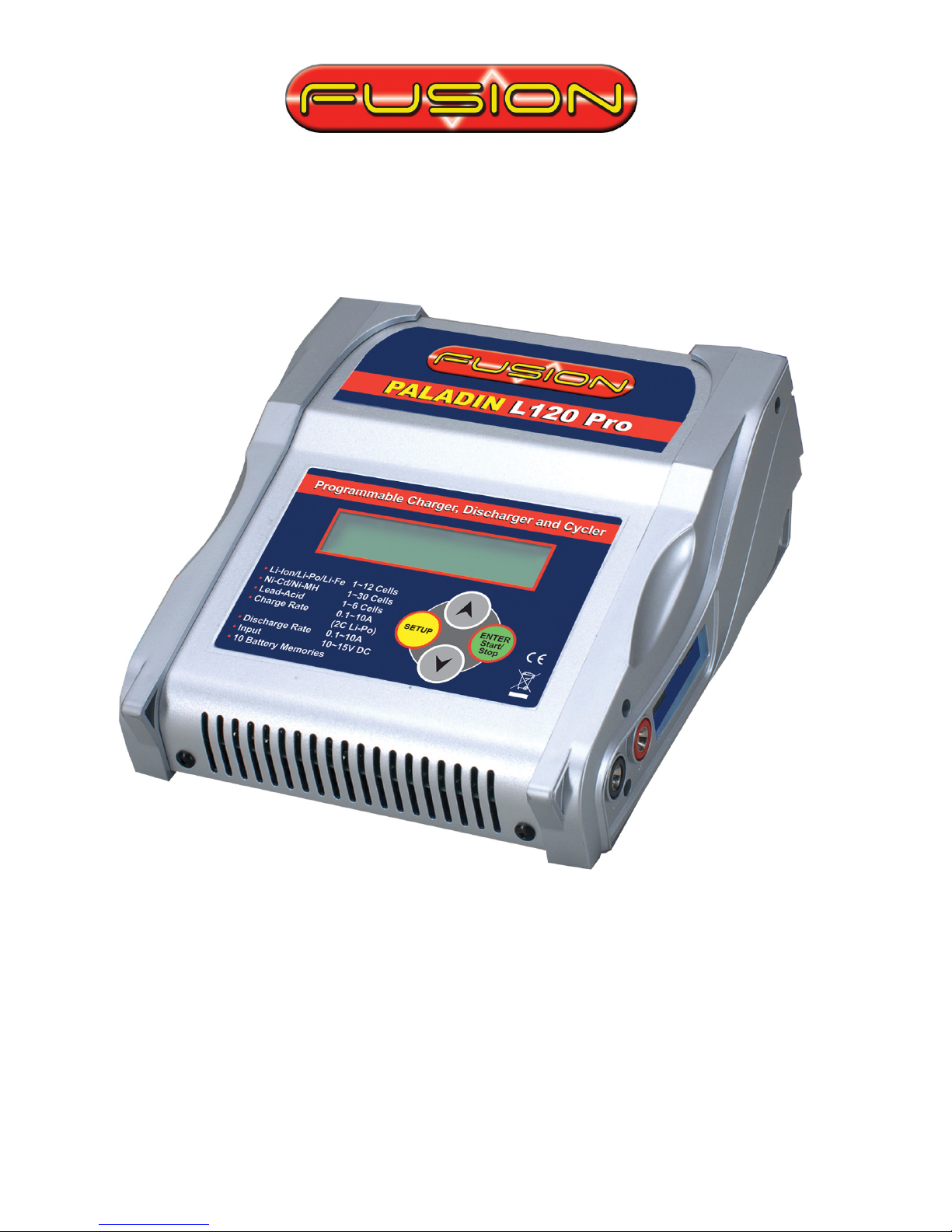
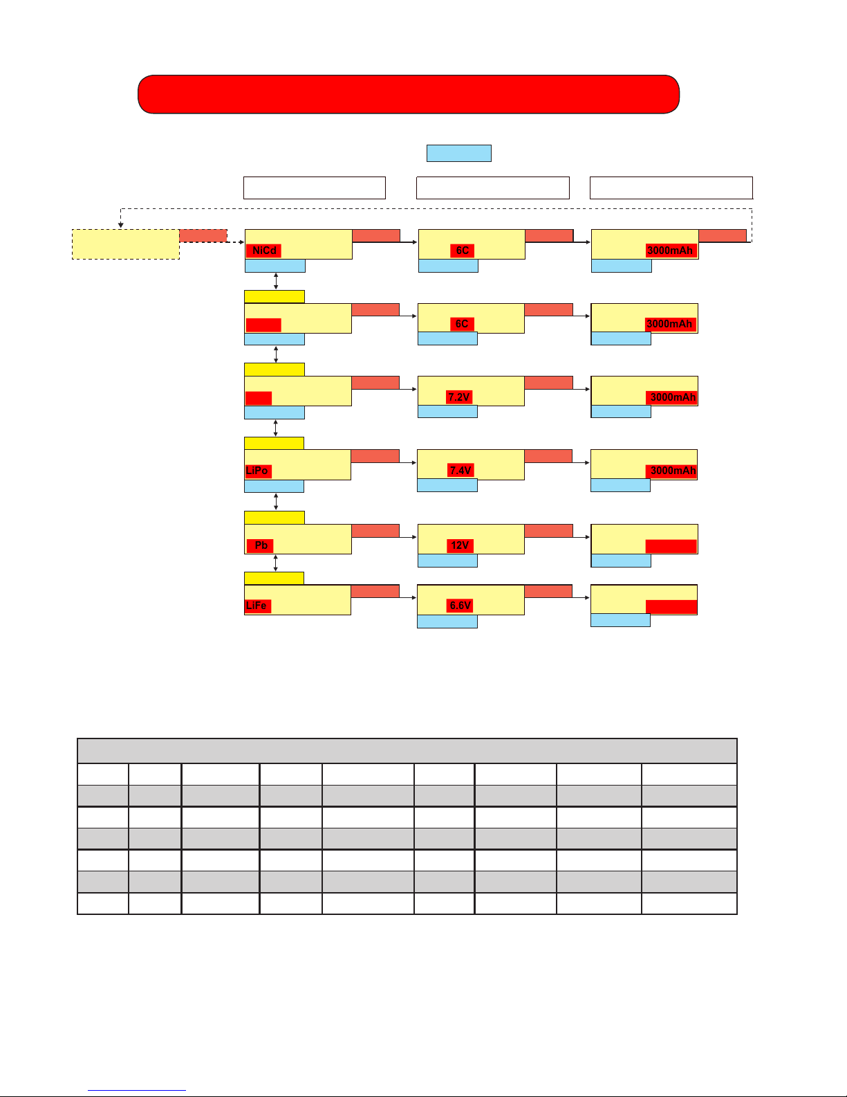
ALWAYS ensure that the charger is correctly set for the battery being
charged, checking both voltage and capacity. Be particularly careful if using
a series/parallel battery pack, or if using packs of different specifications
with the same charger.
NEVER charge at a rate higher than that recommended by the cell
manufacturer, this can be very dangerous.
DO NOT leave Lithium ION/Polymer/Fe batteries unattended whilst they
are charging. Monitoring the batteries during charging is very important.
ALWAYS monitor the temperature of the battery being charged every few
minutes. If the battery becomes hot to the touch, disconnect it from the
charger immediately and allow to cool. DO NOT recommence charging
until the battery and charger have been checked for compatibility and the
charger settings have been confirmed as being correct.
In the unlikely event of the Lithium ION/Polymer/Fe battery catching fire
DO NOT use water to attempt to put the fire out, instead use sand or a
fire extinguisher designed for electrical fires.
When used correctly, Lithium ION/Polymer/Fe battery packs are as safe
as any other type of rechargeable battery pack.However they do require
different charge regimes to the longer established Nickel Cadmium and
Nickel Metal Hydride technologies and have the potential of catching
fire if severely mistreated.
If Lithium Polymer battery packs are short-circuited or severely
over-charged elemental Lithium may be deposited internally, and if the
battery pouch is damaged this can escape from inside the battery. If this
occurs a fire may be caused, as elemental Lithium is highly reactive
when exposed to water or moisture, producing flammable hydrogen
gas and corrosive fumes. Elemental Lithium is not produced unless the
battery pack is severely mistreated, so in normal usage there is no
likelihood of explosion or fire.

4
Lithium Ion/polymEr/FE BAttEriEs
Lithium battery packs must NEVER be discharged below 3 volts per cell
as this will result in damage to the cells. If the voltage is allowed to drop
below 3 volts per cell the battery voltage may seem to recover following a
charge, but the battery may not then give its full nominal capacity and a
reduction in performance is likely – allowing the voltage to drop below 3
volts per cell will invalidate all warranty claims.
NEVER charge Lithium Polymer battery packs at greater than 4.2V per
cell, Lithium Ion at 4.1V volts per cell or LiFe at greater than 3.7V per cell
as this will cause irreversible damage to the cells and will invalidate all
warranty claims.
DO NOT use discharge rates in excess of those specified with the battery
pack as this will result in a significant drop in voltage under load and will
dramatically reduce the number of charge/discharge cycles the battery
pack will give.
DO NOT attempt to charge Lithium battery packs whilst the input
12 volt battery is being charged, as the voltage supplied to the Lithium
Polymer charger may be too high.
If disposing of Lithium battery packs ensure that the pack is fully
discharged by using a light bulb, electric motor or similar to completely
discharge the pack.
DO NOT allow any Lithium battery pack to short-circuit as this is likely to
result in a minor explosion and consequent fire.
BEFORE charging any Lithium battery packs they should be closely
inspected for any damage, such as punctures in the sleeving or if the
battery has swollen or expanded in size. If any such damage is detected
DO NOT charge, even if the battery otherwise appears to be brand new.
Before commencing charging ALWAYS double check the settings on the
charger to ensure it is set correctly for the battery pack to be charged.
Using the wrong settings is likely to result in damage to the battery pack
being charged and could result in the battery catching fire.

5
Input powEr
12V DC
Connect the charger’s red alligator clip to the positive (+) terminal on the
power source and the black alligator clip to the negative (-) terminal. The
charger will display “Input voltage” error message if the input is below 10V
or above 15V. If this happens, please recheck the input power supply to
make sure correct power is present.
Output BAttEry ConnEctions
Two 4mm banana sockets are located on the right side of the charger.
Connect the battery main power leads to these sockets with the positive
(+) lead connected to the red socket and the negative (-) lead to the black
socket. You may need to purchase an adaptor lead to suit the specific
connector on you battery and make this more convenient. The “Connect
Error” error message will be displayed if trying to start charging without
connecting a battery to these sockets. The “Open Circuit” error message
will be displayed if a battery becomes disconnected from the charger
while a function is in progress. A “Reverse Polarity” error message will be
displayed if a battery is connected to the charger in reverse.
Note: In order to balance Lithium batteries during charge or discharge,
please use the appropriate Fusion balancer.

6
1. mAin mEnu
NiCd 10C 3000mAh [NiCd] BATTERY
CHARGE START
DOWN
M0] MEMORY SELECT
NiCd 10C 3000mAh
[NiCd] BATTERY
DISCHARGE START
DOWN
CHARGE MODE
C:5.0A d15V/C
UP
[NiCd] BATTERY
CYCLE START
SETUP
SETUP
DOWN
DICHARGE MODE
D:2.0A 0.8V/CELL
UP
SETUP
DOWN
CYCLE MODE
CHG > DCH TIME 1
UP
SETUP
DOWN
USER CONDITION
SETUP
UP
SETUP
DATA VIEW
BATTERY & CHARGER
UP
FUSION
www.LogicRC.com
DOWN
M0] MEMORY SELECT
NiCd 10C 3000mAh
UP/DOWN
DOWN
A2] MEMORY SELECT
NiMH AUTOMATIC
UP
DOWN
A1] MEMORY SELECT
NiCd AUTOMATIC
UP
M9] MEMORY SELECT
NiCd 10C 3000mAh
UP/DOWN
UP
NiCd 10C 3000mAh
NiCd 10C 3000mAh
C: 5.)A D: 3.0A
6. User data setup menu
5. Cycle data setup menu
7. Data View display
4. Discharge data setup menu
3. Charge data setup menu
2. Battery data setup menu
Select memory locations M0~M9,A1,
and A2 with UP/DOWN button
SETUP
UP
DOWN
SETUP
When the charger is turned on, it will enter the main menu, then use the buttons on
the charger (as shown below) to navigate through the menus.
All the functions have been detailed in the following sections to to help you
familiarise you with the programming and features included in this Paladin L120 Pro.
ENTER
ENTER
ENTER
ENTER
ENTER
ENTER

7
2. BAttEry DAtA SEtup mEnu
In this mode, you can set each battery type / cell number / battery capacity in a
memory. Adjust the desired parameters with buttons.
Factory Default Parameters
CELL CAPACITY CHAGE DISCHARGE DELTA DCH VOLT CYCLE DIR CYCLE TIME
NiCd 6CELL 3000mAh 3.0A 3.0A 5mV 0.8V/CELL CHG>DCH 1TIME
NiMH 6CELL 3000mAh 3.0A 3.0A 5mV 0.8V/CELL CHG>DCH 1TIME
LiPo 7.4V 3000mAh 3.0A 3.0A X 3.0V/CELL X X
Li-Ion 7.2V 3000mAh 3.0A 3.0A X 3.0V/CELL X X
Pb 12V 15.00Ah 3.0A 3.0A X X X X
LiFe 6.6V 3000mAh 3.0A 3.0A X 3.0V/CELL X X
1] MEMORY SELECT
NiCd 6C 3000mAh
SETUP
M1] BATTERY SETUP
NiCd 6C 3000mAh
SETUP
M1] BATTERY SETUP
NiCd 6C 3000mAh
SETUP
DOWN UP/DOWNUP/DOWN
M1] BATTERY SETUP
NiCd 6C 3000mAh
SETUP
M1] BATTERY SETUP
NiMH 6C 3000mAh
SETUP
M1] BATTERY SETUP
NiMH 6C 3000mAh
DOWN UP/DOWNUP/DOWN
M1] BATTERY SETUP
NiMH 6C 3000mAh
SETUP
UP
M1] BATTERY SETUP
LiIo 7.2V 3000mAh
SETUP
M1] BATTERY SETUP
LiIo 7.2V 3000mAh
UP/DOWNUP/DOWN
DOWN
M1] BATTERY SETUP
LiIo 7.2V 3000mAh
SETUP
UP
M1] BATTERY SETUP
Pb 12V 15.00Ah
SETUP
M1] BATTERY SETUP
Pb 12V 15.00Ah
UP/DOWNUP/DOWN
M1] BATTERY SETUP
Pb 12V 15.00Ah
SETUP
UP
Battery Type Change Cell Number Change Battery Capacity Change
M1] BATTERY SETUP
LiFe 6.6V 3000mAh
SETUP
M1] BATTERY SETUP
LiFe 6.6V 3000mAh
UP/DOWN
UP/DOWN
M1] BATTERY SETUP
LiFe 6.6V 3000mAh
SETUP
UP
M1] BATTERY SETUP
LiPo 7.4V 3000mAh
SETUP
M1] BATTERY SETUP
LiPo 7.4V 3000mAh
UP/DOWNUP/DOWN
DOWN
M1] BATTERY SETUP
LiPo 7.4V 3000mAh
SETUP
UP
UP/DOWN
NOTE: The Paladin L120 Pro is supplied with the 10 memories already programmed.
Unless these programs exactly match your requirements, it will be necessary to
modify them to suit the battery packs being charged.

8
3. ChArgE DAtA SEtup mEnu
Li-lon/Po & Pb battery Set the charge capacity. Note: In case of charging Lithium
batteries, it is NOT possible to set charge rates over 2C of the selected battery
capacity.
CHARGE MODE
C5.0A d15mV
SETUP
NiCd & NiMH battery Set charge capacity and Delta peak sensitivity.
UP/DOWN
CHARGE MODE
C5.0A d15mV
SETUP
UP/DOWN
CHARGE MODE
C:5.0A d:15mV
SETUP
CHARGE MODE
C5.0A
SETUP
UP/DOWN
CHARGE MODE
C5.0A
SETUP
DISCHARGE MODE
D2.0A 0.8V/CELL
SETUP
UP/DOWN
DISCHARGE MODE
D2.0A 0.8V/CELL
SETUP
UP/DOWN
DISCHARGE MODE
D2.0A 0.8V/CELL
SETUP
DISCHARGE MODE
D2.0A 3.0V/CELL
SETUP
UP/DOWN
DISCHARGE MODE
D2.0A 3.0V/CELL
SETUP
UP/DOWN
DISCHARGE MODE
D2.0A 3.0V/CELL
SETUP
DISCHARGE MODE
D:2.0A
SETUP
UP/DOWN
DISCHARGE MODE
D:2.0A
SETUP
Li-lon/Pro battery Set discharge rates and discharge cut-off voltages.
PbbatterySetdischargerates(TheDischargecut-offvoltageisxedat1.8Vpercell)
4. DischArgE DAtA SEtup mEnU
NiCd & NiMH battery Set discharge rates and discharge cut-off voltages.
NiCd & NiMH battery only Set cycle direction and cycle times.
CYCLE MODE
CHG DCH 1 TIME
SETUP
UP/DOWN
CYCLE MODE
CHG DCH 1 TIME
SETUP
UP/DOWN
CYCLE MODE
CHG DCH 1 TIME
SETUP
5. CyclE DAtA SEtup mEnu

9
Each user setup data is separately stored in each memory.
All data of the cycle 1 to 5 times can be referred to with UP & DOWN buttons.
Note: LCB means Lithium Cell Balancer.
6. UsEr DAtA SEtup mEnu
USER
CONDITION SETUP
UP/DOWN
TEMPERATURE
CUT-OFF: 00’C
ENTER
SETUP
UP/DOWN
TRICKLE CHARGE
CURRENT: 000mA
ENTER
SETUP
UP/DOWN
DELAY BETWEEN
CHG/DCHG: 00min
ENTER
SETUP
UP/DOWN
BUZZER VOLUME
OFF
ENTER
SETUP
ENTER
UP/DOWN
7=0.00 0.00 0.00
A=0.00 0.00 0.00
SETUP
1=0.00 0.00 0.00
4=0.00 0.00 0.00
SETUP
ENTER
LCB = VOLTAGE [00]
0.000Vavg 0.000V
SETUP
ENTER
CYCLE DATA [1]
C=0000 / D=0000mAh
ENTER
INPUT = 00.000V
OUTPUT = 00.000V
ENTER
SETUP
SET = 00 / PEAK=00.0
TEMP= 00.0°C
ENTER
SETUP
CHG PEAK = 00.000V
000m00s 00000mAh
ENTER
SETUP
DCH AVG = 00.000V
000m00s 00000mAh
ENTER
SETUP
UP/DOWN
SETUP
DATA VIEW
BATTERY & CHARGER
ENTER
UP/DOWN
7. DAtA ViEw DisplAy
1. Input voltage 1. Setting temperature 1. Charge peak voltage 1. Discharge average voltage
2. Output voltage 2. Peak temperature 2. Charge time 2. Dischrge time
3. Temperature now 3. Charge capacity 3. Discharge capacity
SETUP
NiCd 000:00 00000
00° 0.00A 00.00V
CHARGE MODE
C: 5.0A d: 15mV/C
ENTER
CHARGE MODE
C: 5.0A d: 15mV/C
CHG 000:00 00000
00° 0.00A 00.00V
ENTER
2SEC
UP/DOWN
[NiCd] BATTERY
CHARGE START...
DATA VIEW
BATTERY&CHARGER
CHG Batt Type
Flashing alternately TIME CAPACITY STOP
“N/A” should be displayed, if a
temp sensor is not connected to
the charger
The Charge current can be
changed with UP/DOWN
buttons during charging
8. Operating Display
NiCd, NiMH, Pb CHARGE OPERATING
If the (Start/Stop) button is pressed at Charge, Discharge, or Cycle menus, the selected
mode is activated.
It is possible to change charge rates with the buttons during operation, however, the
charge rates can not be adjusted in Auto mode, or during CV (Constant Voltage) charge.
If the button is pressed again during operation, the operation will stop and revert to the
main display.
While the charger is being operated, the DATA VIEW screens can be shown by pressing the
button.
SETUP
ENTER
ENTER
UP/DOWN

10
Note : In this Lithium mode, the charged amount can be shown as a percentage. So, you can
stop charging and disconnect the Lithium battery pack if this percentage is indicated 80% ~ 90%
as you should be able to use this 80%~90% charged battery pack already if you want.
This message will appear if a Lithium cell balancer is NOT
connected to the charger in LiPo and Li-lon mode.
BATT
NiCd 000:00 00000
00° 0.00A 00.00V
DISCHARGE MODE
C:2.0A
ENTER
DISCHARGE MODE
C: 2.0A
DCH 000:00 00000
00° 0.00A 00.00V
ENTER
2SEC
UP/DOWN
[NiCd] BATTERY
DISCHARGE START
DATA VIEW
BATTERY & CHARGER
DCH Batt Type
Flashing alternately TIME CAPACITY STOP
“N/A” should be displayed, if a
temp sensor is not connected
to the charger
The Disharge current can be
changed with UP/DOWN
buttons during discharging
BATT
LiPo 000:00 00000
00° 0.00A 00.00V
DISCHARGE MODE
C: 2.0A
ENTER
DISHARGE MODE
C: 2.0A
DCH 000:00 00000
00° 0.00A 00.00V
ENTER
2SEC
UP/DOWN
[LiPo] BATTERY
DISCHARGE START
DATA VIEW
BATTERY & CHARGER
DCH Batt Type
Flashing alternately TIME
STOP
“N/A” should be displayed,
if a temp sensor is not
connected to the charger
The Discharge current can
be changed with UP/DOWN
buttons during discharging
** BALANCER **
** ADVISED **
CAPACITY
SETUP
LiPo 000:00 00%
00° 0.00A 00.00V
CHARGE MODE
C: 5.0A
ENTER
CHARGE MODE
C: 5.0A
CHG 000:00 00000
00° 0.00A 00.00V
ENTER
(2SEC)
UP/DOWN
[LiPo] BATTERY
CHARGE START...
DATA VEIW BATTERY
& CHARGER
CHG Batt Type
Flashing Alternately TIME Charged amount by Percentage Batt Type Flashing (LiPo, Li-lon Only)
STOP
“N/A” should be displayed,
if a temp sensor is not con-
nected to the charger
The Charge current can be
changed with UP/DOWN
buttons during charging
** BALANCER **
** ADVISED **
This message will appear if a Lithium
cell balancer is NOT connected to the
charger in LiPo and Li-lon mode.
Li-Po, Li-lon, CHARGE OPERATING
NiCd, NiMH, Pb DISCHARGE OPERATING
Li-Po, Li-lon, DISCHARGE OPERATING

11
CYCLE OPERATING
AUTOMATIC OPERATING
While Auto mode is being activated, “auto” “current” is alternately displayed.
AUTOcycleoperationisxedasdischargechargeonce.
Delaytimeisxedas10minutesinAutomode.
NC 000:01 00000
24° 0.00A 00.00V
CHARGE MODE
NiCd AUTOMATIC
ENTER
CHG 000:01 00000
24° auto 00.00V
[NiCd] BATTERY
CHARGE START...
NC 000:01 00000
24° 0.00A 00.00V
DISCHARGE MODE
NiCd AUTOMATIC
ENTER
DCH 000:01 00000
24° auto 00.00V
[NiCd] BATTERY
DISCHARGE START...
D1C 000:01 00000
24° 0.00A 00.00V
CYCLE MODE
NiCd AUTOMATIC
ENTER
D1C 000:01 00000
24° auto 00.00V
[NiCd] BATTERY
CYCLE START...
UP/DOWN
C1D 000:00 00000
00° 0.00A 00.00V
CYCLE MODE
CHG DCH TIME:
ENTER
C1D 000:00 00000
00° 0.00A 00.00V
[NiCd] BATTERY
CYCLE START...
C1D 000:01 00001
26° 6.00A 12.37V
The Charge current can be
changed with UP/DOWN
buttons during charging
CYCLE DISCHARGE
C1D 019:59 01520
26° DELAY 12.37V
C1D 048:23 01520
26° 3.00A 12.37V
CYCLE DELAYCYCLE CHARGE
CYCLE OPERATING MODE
CHARGE “C” FLASH
DELAY “1” FLASH
DISCHARGE “D” FLASH
CYCLE OPERATING MODE
C1D CHARGE, CYCLE TIME, DISCHARGE
D1C DISCHARGE, CYCLE TIME, CHARGE
END OPERATION
If the button is pressed for 2 seconds in the END display, it reverts to the main display.
(Ifthebuttonisbrieypressedorthebatterypackisdisconnected,itwon’treverttothe
main display.)
Operating data can be referred to the above “7. Data View Display “
During trickle charging, the parameters of “ CHG, TRK, FINISH, trickle current “ are blinking.
Trickle charge
If trickle currents are set to 100~500mAh at “USER CONDITION SETUP”, the trickle charge•
proceeds with the selected trickle currents.
The trickle charge proceeds with 1/20 currents of the selected capacity in Auto mode,•
however, there is NO trickle charge in cases of lower than 100mAh.
Even if the trickle currents are set, if a charge process is stopped due to the optional•
temperature, or safety-timer function, the trickle charge won’t work at all.
ENTER
TRK 120:35 03215
38° FINISH 9.12V
CHG 120:35 03215
38° 5.00A 9.12V
CHARGE MODE
C: 5.0Ad: 15mV/C
CHG 120:35 03215
38° 0.10A 9.12V
ENTER
DCH 38.24 02400
36° FINISH 4.80V
DCH 38:24 02400
36° 2.00A 4.80V
DISCHARGE MODE
C: 2.0A: 0.8V/CELL
ENTER
C1D 142:34 02860
37° FINISH 4.82V
C1D 042:34 02860
37° 2.00A 4.82V
CYCLE MODE
CHC DCH TIME:1
2 SEC
2 SEC
2 SEC
ENTER
ENTER

12
10. mEssAgE DisplAy
INPUT VOLTAGE
ERROR 0.00Vi
OUTPUT BATTERY
CONNECT ERROR
OUTPUT BATTERY
REVERSE POLARITY
OUTPUT BATTERY
OPEN CIRCUIT
OUTPUT CIRCUIT
PROBLEM
PAUSE...
CHARGER TOO HOT
OUTPUT VOLTAGE
TOO HIGH 0.00V
OUTPUT VOLTAGE
TOO LOW 0.00V
TEMPERATURE
SENSOR ERROR
BATT. TEMPERATURE
TOO HIGH 00.0°C
INTERNAL TEMP
SENSOR ERROR
DATA COMMUNICA-
TION ERROR
When the input voltages exceed the range of 9.5~15.5V.
When the charger starts without connecting to the battery pack.
When the battery pack is disconnected during operation.
When the battery terminals short-circuit for a while.
When the temperature of the charger rises over 115°C, the charger stops
temporarily until the temperature drops lower than 70°C.
When the output voltges are too high.
When the output voltages are too low.
When the thermal probe is incorrectly connected, or the probe is defective.
When the temperature of the battery pack is higher than the selected tempera-
ture, this message is shown. The previous operation should resume when the
temperature of the battery pack becomes 2°C lower than the selected temp.
When the temperature of the charger rises over 125°C.
When the charger starts without connecting the battery pack in reverse.
When the internal interface of the charger is defective.

13

Logic RC Limited
14 Hartham Lane
Herford
SG14 1QN
United Kingdom
www.LogicrC.com
Table of contents
Other Fusion Batteries Charger manuals

Fusion
Fusion NX87 User manual

Fusion
Fusion NX86 User manual

Fusion
Fusion VECTOR NX81 User manual

Fusion
Fusion ELYSIUM LX60B Pro User manual

Fusion
Fusion TYPHOON L50B PRO User manual

Fusion
Fusion ECLIPSE LX61B Pro User manual

Fusion
Fusion VECTOR AC/DC NX85 User manual

Fusion
Fusion 5IVE NX82 User manual

Fusion
Fusion EMPEROR L702B User manual

Fusion
Fusion NX85 User manual