Efco SA 2700 Assembly instructions

OPERATOR’S INSTRUCTION MANUAL
MANUEL D’UTILISATION ET D’ENTRETIEN
MANUAL DE INSTRUCCIONES
en
fr
es
SA 2700
(1.86 cu.in)

en
2
To correctly use the blower and prevent accidents, do not start work without having first
carefully read this manual. You will find explanations concerning the operation of the
various parts plus instructions for necessary checks and relative maintenance.
Note: Illustrations and specifications in this manual may vary according
to Country requirements and are subject to change without notice by the
manufacturer.
THE OPERATOR’S MANUAL
Your operator’s manual is for your protection. READ IT. Keep it in a safe place for
reference. Know what you are doing before you begin assembly of the unit. Proper
preparation and upkeep go hand-in-hand with satisfactory performance of the blower
and safety.
Contact your dealer or the distributor for your area if you do not understand any of the
instructions in this manual.
In addition to the operating instructions, this manual contain paragraphs that require
your special attention.
Such paragraphs are marked with the symbols described below:
Warning: where there is a risk of an accident or personal injury or serious damage to
property.
Caution: where there is a risk of damaging the machine or its individual components.
WARNING - To ensure safe and correct operation of the blower
this operator's manual should always be kept with or near the
machine. Do not lend or rent your blower without the operator's
instruction manual.
WARNING: Allow only persons who understand this manual to
operate your blower.
Except where especially noted (wording “VACUUM MACHINE”) what noted in the
operator’s manual can be referred to both blower and vacuum configurations.
INTRODUCTION

en
3
PRODUCT IDENTIFICATION
Blower Components . . . . . . . . . . . . . . . . . . . . . . . . . . . . . . . . . . . . . . . . . . . . . . . . . . . . . . . . . . . 4
SAFETY
Understanding Safety Labels . . . . . . . . . . . . . . . . . . . . . . . . . . . . . . . . . . . . . . . . . . . . . . . . . . . . 5
State and Local Requirements . . . . . . . . . . . . . . . . . . . . . . . . . . . . . . . . . . . . . . . . . . . . . . . . . . . 5
SAFETY RULES
Basic Safety Precautions . . . . . . . . . . . . . . . . . . . . . . . . . . . . . . . . . . . . . . . . . . . . . . . . . . . . . . . 7
Fuel Handling . . . . . . . . . . . . . . . . . . . . . . . . . . . . . . . . . . . . . . . . . . . . . . . . . . . . . . . . . . . . . . . . 8
Operation and Safety . . . . . . . . . . . . . . . . . . . . . . . . . . . . . . . . . . . . . . . . . . . . . . . . . . . . . . . . . . 8
Precautions to Reduce Vibration Risk . . . . . . . . . . . . . . . . . . . . . . . . . . . . . . . . . . . . . . . . . . . . . 9
Maintenance Precautions . . . . . . . . . . . . . . . . . . . . . . . . . . . . . . . . . . . . . . . . . . . . . . . . . . . . . . . 9
ASSEMBLY
Tubes Assembly . . . . . . . . . . . . . . . . . . . . . . . . . . . . . . . . . . . . . . . . . . . . . . . . . . . . . . . . . . . . . . 10
OPERATION
Fueling. . . . . . . . . . . . . . . . . . . . . . . . . . . . . . . . . . . . . . . . . . . . . . . . . . . . . . . . . . . . . . . . . . . . . . 12
Preparation for Working . . . . . . . . . . . . . . . . . . . . . . . . . . . . . . . . . . . . . . . . . . . . . . . . . . . . . . . . 13
Starting the Engine . . . . . . . . . . . . . . . . . . . . . . . . . . . . . . . . . . . . . . . . . . . . . . . . . . . . . . . . . . . . 16
Breaking-in the Engine . . . . . . . . . . . . . . . . . . . . . . . . . . . . . . . . . . . . . . . . . . . . . . . . . . . . . . . . . 17
Stopping the Engine . . . . . . . . . . . . . . . . . . . . . . . . . . . . . . . . . . . . . . . . . . . . . . . . . . . . . . . . . . . 17
MAINTENANCE
Maintenance Chart . . . . . . . . . . . . . . . . . . . . . . . . . . . . . . . . . . . . . . . . . . . . . . . . . . . . . . . . . . . . 18
Idle Speed Adjustment . . . . . . . . . . . . . . . . . . . . . . . . . . . . . . . . . . . . . . . . . . . . . . . . . . . . . . . . . 19
Fuel Filter. . . . . . . . . . . . . . . . . . . . . . . . . . . . . . . . . . . . . . . . . . . . . . . . . . . . . . . . . . . . . . . . . . . . 19
Air Filter. . . . . . . . . . . . . . . . . . . . . . . . . . . . . . . . . . . . . . . . . . . . . . . . . . . . . . . . . . . . . . . . . . . . . 19
Starter Unit . . . . . . . . . . . . . . . . . . . . . . . . . . . . . . . . . . . . . . . . . . . . . . . . . . . . . . . . . . . . . . . . . . 19
Engine . . . . . . . . . . . . . . . . . . . . . . . . . . . . . . . . . . . . . . . . . . . . . . . . . . . . . . . . . . . . . . . . . . . . . . 19
Spark Plug. . . . . . . . . . . . . . . . . . . . . . . . . . . . . . . . . . . . . . . . . . . . . . . . . . . . . . . . . . . . . . . . . . . 20
Spark Arresting Muffler . . . . . . . . . . . . . . . . . . . . . . . . . . . . . . . . . . . . . . . . . . . . . . . . . . . . . . . . . 20
Safety Guard . . . . . . . . . . . . . . . . . . . . . . . . . . . . . . . . . . . . . . . . . . . . . . . . . . . . . . . . . . . . . . . . . 20
TROUBLE SHOOTING
Using Trouble shooting Chart . . . . . . . . . . . . . . . . . . . . . . . . . . . . . . . . . . . . . . . . . . . . . . . . . . . . 21
STORAGE
Storing Blower. . . . . . . . . . . . . . . . . . . . . . . . . . . . . . . . . . . . . . . . . . . . . . . . . . . . . . . . . . . . . . . . 22
VACUUM KIT (OPTIONAL)
Assembly. . . . . . . . . . . . . . . . . . . . . . . . . . . . . . . . . . . . . . . . . . . . . . . . . . . . . . . . . . . . . . . . . . . . 23
Use . . . . . . . . . . . . . . . . . . . . . . . . . . . . . . . . . . . . . . . . . . . . . . . . . . . . . . . . . . . . . . . . . . . . . . . . 24
Maintenance . . . . . . . . . . . . . . . . . . . . . . . . . . . . . . . . . . . . . . . . . . . . . . . . . . . . . . . . . . . . . . . . . 25
TECHNICAL DATA
SA 2700. . . . . . . . . . . . . . . . . . . . . . . . . . . . . . . . . . . . . . . . . . . . . . . . . . . . . . . . . . . . . . . . . . . . . 26
TABLE OF CONTENTS

en
4
Blower Components
1 - Nozzle
2 - Blower tube
3 - Throttle trigger
4 - Throttle Trigger Lock
5 - Safety guard
6 - Throttle limiter
7 - On/Off switch
8 - Spark plug
9 - Primer bulb
10 - Choke lever
11 - Air cleaner cover
12 - Fuel tank cap
13 - Fuel tank
14 - Starting handle
15 - Muffler
16 - Tube securing screw
17 - Combination Wrench
PRODUCT IDENTIFICATION

en
5
SAFETY
- This symbol indicates Warning, and
Caution.
- Your manual contains special
messages to bring attention to
potential safety concerns, machine
damage as well as helpful operating
and servicing information. PLEASE
READ ALL THE INFORMATION
CAREFULLY TO AVOID INJURY
AND MACHINE DAMAGE.
- Wear eye, hearing and head
protection when operating this
equipment.
- WARNING! Danger of finger
amputation
- WARNING: the surface can be hot!.
- WARNING! The blower may throw
objects at high velocity that can
ricochet and hit the operator. This
may cause serious eye damage.
- The blower operator must make
sure that no bystanders or
animals come nearer than 35 feet
(10 metres). Whenever several
operators are working in the same
work area, they should maintain a
safe distance of at least 35 feet (10
metres) from one another.
- Noise pressure level measured at 50
feet (15 metres) distance according
to ANSI B175.2-1996
Understanding Safety Labels
State and Local Requirements
Your engine is equipped with a temperature limiting muffler, a spark arresting screen in order to comply
with the requirements of SAE Recommended Practice J335 and California Codes 4442 and 4443. All
national forest land and land managed by the states of California, Maine, Washington, Idaho,
Minnesota, New Jersey and Oregon require internal combustion engines to be equipped with a
spark arrester screen by law. Other states and federal agencies are enacting similar regulations.
If you operate a blower in a state or locale where such regulations exist, you are legally responsible for
maintaining the operating condition of these parts. Failure to do so is a violation of a law. Spark arrester
maintenance is described in the Maintenance-Spark Arresting Muffler Section of the manual.
Note: When using a blower for logging purposes, refer to Code of Federal Regulations, Parts 1910
and 1928.
WARNING: The ignition system of your unit produces an electromagnetic field of a very
low intensity. This field may interfere with some pacemakers. To reduce the risk of serious
or fatal injury, persons with pacemaker should consult their physician and the pacemaker
manufacturer before operating this tool.
WARNING: Muffler surfaces are very hot during and after operation of the blower, keep all
body parts away from the muffler. Serious burns may occur if contact is made with the
muffler.
71
dB(A)
per ANSI B175.2-1996

en
6
WARNING: Exposure to vibrations through prolonged use of gasoline powered hand tools
could cause blood vessel or nerve damage in the fingers, hands, and wrists of people
prone to circulation disorders or abnormal swellings. Prolonged use in cold weather has
been linked to blood vessel damage in otherwise healthy people. If symptoms occur such
as numbness, pain, loss of strength, change in skin color or texture, or loss of feeling in the
fingers, hands, or wrists, discontinue the use of this tool and seek medical attention.
WARNING: The engine exhaust from this product contains chemicals known to
the State of California to cause cancer, birth defects or other reproductive harm.
Operate your blower outdoors only in a well ventilated area.
SAFETY

en
7
1
SAFETY RULES
Basic Safety Precautions
• Read this manual carefully until you completely understand
and can follow all safety rules, precautions, and operating
instructions before attempting to use the unit.
• Restrict the use of your blower to adult users who understand
and can follow safety rules, precautions, and operating
instructions found in this manual. Minors should never be
allowed to use a blower.
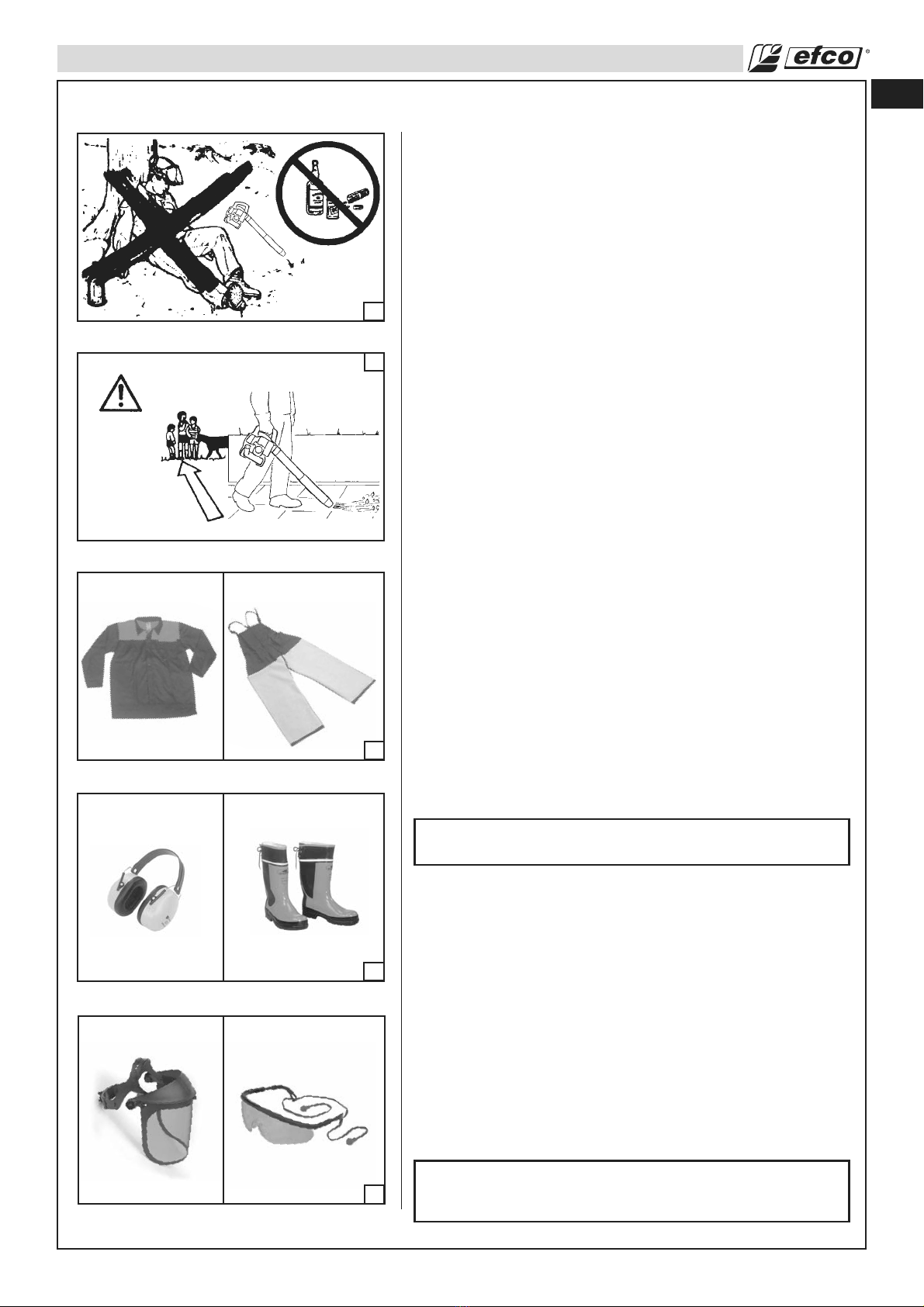
• Do not handle or operate a blower when you are fatigued, ill,
or upset, or if you have taken alcohol, drugs, or medication.
You must be in good physical condition and mentally alert.
Blower work is strenuous. If you have any condition that might
be aggravated by strenuous work, check with your doctor
before operating a blower (Fig. 1). Be more cautious before
rest periods and towards the end of your shift.
• Keep children, bystanders, and animals a minimum of 35 feet
(10 meters) away from the work area. Do not allow other
people or animals to be near the blower when starting or
operating the blower (Fig. 2).
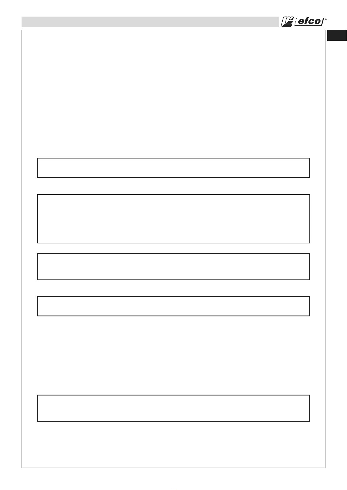
• While working with the blower, always use safety protective
approved clothing. The use of protective clothing does not
eliminate injury risks, but reduces the injury effects in case of
accident. Consult your trusted supplier to choose equipment in
compliance with legislation. The clothing must be proper and
not an obstacle. Wear adherent protective clothing. Protective
jackets (Fig.3) and dungarees (Fig.3) are ideal. Do not wear
clothes, scarves, ties or bracelets that get stuck in wood or
twigs. Tie up and protect long hair (example with foulards, cap,
helmets, etc.). Wear safety boots having skid-proof sole
and anti-piercing insert (Fig.4). Wear protective goggles
or face screens (Fig.5). Use protections against noises: for
example noise reduction ear guards (Fig.4) or earplugs.
The use of protections for the ear is very important, because
the perception of danger audio signals (screaming, alarms,
etc.) is limited. Always remove your hearing protection as
soon as the engine stop. Wear gloves (Fig.6, page 8) that
permit the maximum absorption of vibrations.
WARNING – Wear face mask when operating the
blower in dusty environments.
• Only loan your blower to expert users who are completely
familiar with blower operation and correct use. Give other
users the manual with operating instructions, which they have
to read before using the blower.
• Check the blower each day to ensure that each device,
whether for safety or otherwise, is functional.
• Never use a damaged, modified, or improperly repaired or
assembled blower. Do not remove, damage or deactivate any
of the safety devices.
• Carefully plan your blowing operation in advance. Do not start
blowing until you have a clear work area, secure footing.
• All blower service, other than the operations shown in the present
manual, have to be performed by competent personnel.
• It is unadvisable to hitch tools or applications to the P.t.o. that
are not specified by the manufacturer.
WARNING - The blower may throw objects at high
velocity that can ricochet and hit the operator. This may
cause serious eye damage. Always wear eye protection.
2
3
4
5
≥ 35 ft

en
8
Fuel Handling
WARNING: Gasoline is an extremely flammable fuel.
Use extreme caution when handling gasoline or fuel
mix. Do not smoke or bring any fire or flame near the
fuel or the blower (Fig. 7).
•To reduce the risk of fire and burn injury, handle fuel with
care. It is highly flammable.
• Mix and store fuel in a container approved for gasoline (Fig. 8).
• Mix fuel outdoors where there are no sparks or flames.
• Select bare ground, stop engine, and allow to cool before
refueling.
• Loosen fuel cap slowly to release pressure and to keep fuel
from escaping around the cap.
• Tighten fuel cap securely after refueling. Unit vibration can
cause an improperly tightened fuel cap to loosen or come off
and spill quantities of fuel.
• Wipe spilled fuel from the unit. Move 10 feet (3 m) away from
refueling site before starting engine (Fig. 9).
• Never attempt to burn off spilled fuel under any circumstances.
• Do not smoke while handling fuel or while operating the blower.
• Store fuel in a cool, dry, well ventilated place.
• Never place the blower in a combustible area such as dry
leaves, straw, paper, etc.
• Store the unit and fuel in an area where fuel vapors cannot
reach sparks or open flames from water heaters, electric
motors or switches, furnaces, etc.
• Never take the cap off the tank when the engine is running.
• Never use fuel for cleaning operations.
• Take care not to get fuel on your clothing.
Operation and Safety
WARNING: Use a firm grip with thumbs and fingers
encircling the blower handles.
• Keep all parts of your body away from the blower when the
engine is running.
• Always carry the blower with the engine stopped. When
transporting in a vehicle properly secure your blower to
prevent turnover, fuel spillage and damage to the blower.
• Before you start the engine, make sure the blower is not
directed to people.
• Shut off the engine before setting down the blower. Do not
leave the engine running unattended.
• Only use the blower in well-ventilated places, do not operate
the blower in explosive or flammable atmospheres or in closed
environments (Fig. 10).
Warning: Beware of carbon monoxide poisoning.
• Do not operate blower from a ladder, in a tree or on a rooftop.
Always work from a firm-footed and safe position.
• Do not work near electric cables.
• Keep the handle dry, clean, and free of oil or fuel mixture.
• Stand with your weight evenly balanced on both feet.
• Do not overreach. You could be drawn or thrown off balance
and lose control of the blower.
SAFETY RULES
6
7
8
9
10
≥ 10 ft

en
9
SAFETY RULES
Precautions to Reduce Vibration Risk
• The blower is provided with anti-vibration (AV) system; never alter or modify it.
• Wear gloves and keep your hands warm.
• Maintain a firm grip at all times, but do not squeeze the handles with constant, excessive pressures,
take frequent breaks. All the above mentioned precautions do not guarantee that you will not sustain
whitefinger disease or carpal tunnel syndrome. Therefore, continual and regular users should monitor
closely the condition of their hands and fingers. If any of the above symptoms appear, seek medical
advice immediately.
Maintenance Precaution
WARNING: Never operate a blower that is damaged, improperly adjusted, or is not
completely and securely assembled.
WARNING: All blower service, other than items in the Operator's Manual maintenance
instructions, have to be performed by competent blower service personnel. (If improper
tools are used to remove the flywheel or clutch, or if an improper tool is used to hold the
flywheel in order to remove the clutch, structural damage to the flywheel could occur which
could subsequently cause the flywheel to burst and serious injury could result.)
WARNING:
Never modify your blower in any way.
Keep the handles dry, clean, and free of oil or fuel mixture.
WARNING: Use only accessories and replacement parts recommended.
• Never attempt to service the blower while the engine is running.
• Never use fuel for cleaning operations.
• Keep the blower in a dry place, off the ground and the tanks empty.
• If your blower is no longer usable, dispose of it properly without damaging the environment by
handing it in to your local Dealer who will arrange for its correct disposal.
• Replace immediately any safety device when damaged or broken.
WARNING: The muffler and other parts of the engine (e.g. fins of the cylinder, spark
plug) become hot during operation and remain hot for a while after stopping the engine.
To reduce risk of burns do not touch the muffler and other parts while they are hot.

en
10
ASSEMBLY
The machine is supplied ready for use in the blower version.
The kit, supplied separately as an optional accessory, allows the
machine to be used as a vacuum / shredder (see page 23-24-25).
Tubes assembly
WARNING – When fitting the tube and nozzle, the
engine must be off and the switch in the STOP
position.
For ease of assembly, the two pins (A, Fig.11-12) on the housing
and on the tubes are two different sizes. This means that the
tubes cannot be assembled incorrectly.
1. Fit the blower tube (B, Fig.13), so that the two pins (A) on the
spigot of the impeller housing engage the two slots (C) in the
blower tube. Rotate the blower tube in the direction of the
arrow (2). When fitted, tube should appear as shown in Fig.
14. Secure the tube with the screw (G, Fig.14).
2. Fit the nozzle (D, Fig.15) on to the tube (B), so that the two
pins (E) on the blower tube engage the two slots (F) in the
nozzle. Rotate the nozzle in the direction of the arrow (2).
When fitted nozzle should appear as shown in Fig. 16.
3. OPTIONAL – To obtain a more directional and effective
jet of air when blowing, the duckbill style outlet can be
fitted to the tube (Fig.17) in place of the nozzle. The kit, p/n
56552002, can be purchased separately. To assemble, follow
the instructions of point 2. When fitted, the duckbill tube will
appear as in Fig.18.
11
13
14
15
12

en
11
ASSEMBLY
16
18
17

en
12
OPERATION
Fueling (Do Not Smoke!) (Fig. 21)
This product is powered by a 2-cycle engine and requires
pre-mixing gasoline and 2-cycle oil. Pre-mix unleaded gasoline
and 2-cycle engine oil in a clean container approved for gasoline
(Fig. 19).
RECOMMENDED FUEL: THIS ENGINE IS CERTIFIED TO
OPERATE ON UNLEADED GASOLINE INTENDED FOR
AUTOMOTIVE USE WITH AN OCTANE RATING OF 89 ([R + M] / 2)
OR HIGHER (Fig. 20).
Mix 2-Cycle Engine Oil with gasoline according to the instructions
on the package.
We strongly recommend the use of 2% (1:50) Efco Two Cycle
Engine Oil, which is specifically formulated for all Efco air-cooled
two-stroke engines.
The correct oil / fuel proportions shown in the table below
are suitable when using the Efco Two Cycle Engine Oil or an
equivalent high-quality engine oil (JASO specification FD or ISO
specification L-EGD).
When oil specifications are NOT equivalent or unknown use 4%
(1:25) oil / fuel mixing ratio.
CAUTION: DO NOT USE AUTOMOTIVE OIL OR
2-CYCLE OUTBOARD OIL.
CAUTION: Never use a fuel with an alcohol percentage
higher than 10%; gasohol up to 10% alcohol or E10
fuel are acceptable.
When using an Oxygenated Gasoline a good practice of Fuel
Management is necessary.
Gasoline Oxygenated with alcohol readily takes/up water when it
is present; the water may be condensed out of humid air or be a
contaminant in the fuel system, including tank.
CAUTION:
- Match your fuel purchases to your consumption;
don’t buy more than you will use in one or two
months;
- Store gasoline in a tightly-closed container in a
cool, dry place.
The use of Oxygenated Gasoline may cause the occurrence of
vapor-lock easier.
NOTE: 2-Cycle Engine Oil contains a fuel stabilizer and will stay
fresh up to 30 days. DO NOT mix quantities larger than usable
in a 30 day period. A 2-cycle oil containing a fuel stabilizer is
recommended.
Fuel Mixture
2-Cycle Engine Oil (25:1) 4%
Gasoline Oil
1 Gallon (US) . . . . . . . . . . . . . . . . . . . . . . . . . . 5.2 oz.
1 Liter . . . . . . . . . . . . . . . . . . . . . . . . . . . . . . . . 40 cc (40 ml)
19
20
21

en
13
OPERATION
High Quality 2-Cycle Engine Oil (50:1) 2%
Gasoline Oil
1 Gallon (US) . . . . . . . . . . . . . . . . . . . . . . . . . . 2.6 oz.
1 Liter . . . . . . . . . . . . . . . . . . . . . . . . . . . . . . . . 20 cc (20 ml)
Filling the Tank
WARNING: Follow safety instruction for fuel handling.
Always shut off engine before fueling. Never add fuel
to a machine with a running or hot engine. Move at
least 10 feet (3 m) from refueling site before starting
engine (Fig. 22). DO NOT SMOKE!
1. Clean surface around fuel cap to prevent contamination.
2. Loosen fuel cap slowly.
3. Carefully pour fuel mixture into the tank. Avoid spillage.
4. Prior to replacing the fuel cap, clean and inspect the gasket.
5. Immediately replace fuel cap and hand tighten. Wipe up any
fuel spillage.
NOTE: It is normal for smoke to be emitted from a new
engine during and after first use.
WARNING: Check for fuel leaks, if any are found,
correct before use. Contact a Servicing Dealer if
necessary.
Preparation for Working
1. Operate the blower only at reasonable hours, i.e. not early in
the morning or late at night when people might be disturbed.
Comply with times listed in local ordinances.
2. Operate the blower at the lowest possible throttle setting to do
the job.
3. Check the condition of the blower before operation, especially
the muffler, air intake and air filter.
4. Under dusty conditions, slightly spray the work area with a
hose or use a mister attachment when water is available.
5. Watch out for children, pets, open windows or cars, and blow
debris safely away.
6. Use the full nozzle extension so the air stream can work close
to the ground.
7. After using the blower, clean up and dispose of debris in trash
receptacles.
What do leaf blowers do?
You can use a leaf blower to (Fig.23-24-25):
• Remove and gather leaves. To remove rubbish or grass
cuttings from roads, footpaths, parks, parking lots, outhouses
and sports grounds, etc.
• Remove grass clippings
• Dislodge or break up matted grass
• Clean parking lots
• Clean farm and construction equipment
• Clean arenas and amusement parks
• Remove light or fluffy snow
• Dry off pavement and outdoor areas
• To remove rubbish from corners, round connections, and
between paving stones, etc.
22
23
24
25
≥ 10 ft

en
14
OPERATION
Operating courtesy
• Follow local rules and ordinances about when to use leaf
blowers. Do not use very early in the morning or very late in
the day.
• Check wind direction and intensity. Never point the nozzle or
blow debris toward people, pets, cars or houses.
• Do not blow debris toward open windows or doors.
• Always be considerate of people passing by and of property.
• Do not leave the blower running when unattended.
• Do not use a blower to spread or mist fertilizers, chemicals
or other toxic substances, fuel, unless it is designed for these
purposes and in an appropriate area.
• Use the lowest possible throttle speed to do the job (Fig.26).
• Avoid using more than one machine at a time, especially
in neighborhoods or around buildings where sound can be
intensified.
Reducing dust (Fig.27)
• Pay attention to what you are moving.
• Practice moving grass clippings or a paper cup without moving
dust.
• Wet dusty areas down first before using a blower.
• Never use a leaf blower to move excessively dusty materials.
• A leaf blower should NOT be used to clean up:
— Large amounts of gravel or gravel dust
— Construction dirt
— Plaster dust
— Cement and concrete dust
— Dry garden topsoil
WARNING!– Dust with silica in its composition may
contain crystalline silica. Silica is a basic component
of sand, quartz, brick, clay, granite and numerous
other materials and rock, including masonry and
concrete products. Repeated and / or substantial
inhalation of airborne crystalline silica can cause
serious or fatal respiratory disease, including
silicosis. In addition, the state of California and some
other authorities have listed respirable crystalline
silica as a substance known to cause cancer. When
encountering such materials, always follow the
respiratory precautions mentioned above.
WARNING!– Breathing asbestos dust is dangerous
and can cause severe or fatal injury, respiratory
illness or cancer. The use and disposal of asbestos
containing products have been strictly regulated by
OSHA and the Environmental Protection Agency. Do
not blow or disturb asbestos or asbestos containing
product, such as asbestos insulation. If you have
any reason to believe that you might be disturbing
asbestos, immediately contact your employer or
local OSHA representative.
If the substance being blown is a commercial substance, review
the material safety data sheet for that substance or consult the
material manufacturer.
26
27

en
15
OPERATION
To blow away debris on the ground
WARNING! - When fitting the blower tube and nozzle,
the engine must be switched off and the stop switch
must be in the stop position.
The speed of the air jet is regulated by means of the throttle (A, Fig.28).
Select the speed which is best suited for the application. Once
the setting is identified, the throttle limiter (B, Fig.28) can be used
to maintain and retrieve it accurately.
Full throttle is obtained when the limiter (B) is pushed fully up.
Blowing
The blower is designed to be used with one hand only and can
be held in either the left or right hand.
The blower is equally suitable for use on uneven ground (e.g.
grassy areas) and flat areas covered in sawdust, leaves, grass
cuttings and similar material.
On flat surfaces, a more efficient blowing action will be obtained
using the “duckbill” tube p/n 56552002, which can be purchased
separately. This tube generates a broad and powerful stream of
air at ground level, which can be directed and controlled more
accurately than with the standard nozzle.
The throttle stop (B, Fig. 28) is used to set different engine
speeds and consequently to adjust the air jet. Before switching
off the engine, move the throttle stop to the minimum position.
WARNING – Constantly check the area in which you
are working: never direct the air jet towards people or
animals (Fig.29).The blower can propel small objects
at very high speed. Stop the engine immediately if
you are approached.
WARNING! – Never remove the safety guard (B,
Fig.31) when the engine is running. The fan rotor (E)
could cause serious bodily injury, especially to the
hands.
Never start the blower if the safety guard is not
closed, is damaged or cannot be closed.
Always check that the safety guard (B, Fig.31) is
properly closed with the catch (C, Fig.32) securely
locked. Risk of finger injury or amputation.
WARNING! - When working with the blower, wear the
required protecting equipment (Fig.30):
1. Hearing protection.
2. Eye protection.
3. Face mask in dusty environments.
WARNING! - Be careful, particularly if left hand
operation is applied. Avoid any direct body contact
with the exhaust outlet area.
WARNING! - Do not operate the blower while standing
on a ladder or a stand.
WARNING - Don’t walk backward while operating the
machine.
WARNING - Never attempt to blow hot or burning
substances or combustible fluids.
28
29
30
31
32

en
16
CAUTION – Be considerate when using the blower.
Do not operate the machine early morning or late
evening. Observe local noise control by-laws.
OPTIONAL – For increased operator comfort, a single harness is
available (Fig.33), p/n 61140011, which can be purchased separately.
Attach the snap hooks to the loops on the handle (D, Fig.34).
Start the blower as described on page 16. Work according to the
following instructions:
1. Never blow air toward fixed objects such as walls, large rocks,
automobiles and fences.
2. When working inside corners, blow from the corner and inward
toward the center of the work area. Otherwise, debris can fly
up in your face and cause eye injury.
3. Never point the blower nozzle at delicate plants.
Work Area Precautions
• Never allow children to operate your blower. Only allow others
to use this blower who have read this Operator's Manual or
received adequate instructions for the safe and proper use of
this blower.
• Do not work near electrical wires or buildings.
• Work only when visibility and light are adequate for you to see
clearly.
• Do not work from a ladder, this is extremely dangerous.
Leave this operation for professionals.
• Stop the engine before setting the blower down.
• Be particularly cautious and alert while wearing hearing
protection because such equipment may restrict your ability to
hear sounds indicating danger (calls, signals, warnings, etc).
• Be extremely cautious when working on slopes or uneven
ground.
Starting The Engine
• Check that the throttle trigger (A, Fig.35) functions correctly
and the throttle limiter (B) is set to the minimum position.
• Prime the carburetor by slowly push the purge bulb 6 to 8
times (C, Fig.36).
• Position the switch (D, Fig.35) on "I" position.
• Turn the starter lever (F, Fig.38) to the “CLOSE” position.
• Pull throttle lever (B, Fig.37) and lock it in the half-throttle
position by pressing button (E), then release lever (B).
• Rest the blower on the ground in a stable position. While
holding the blower firmly (Fig.39), pull the starter rope hard a
few times until the engine starts (no more than five (5) pulls).
A new unit may require additional pull. When pulling the
starter rope, do not use the full extent of the rope as this can
cause the rope to break. Do not let starter rope snap back.
Hold the handle and let the rope rewind slowly.
• When the engine begins to turn, bring the choke lever (F,
Fig. 38) back to the original position «OPEN». Repeat the
procedure until the engine starts.
• Once the engine is running, press the throttle after 30-40
seconds (B, Fig.37) to release it from the half-throttle position
and let the engine idle.
OPERATION
33
34
35
36
37

en
17
OPERATION
NOTE - STARTING WARM ENGINE:
Follow above starting instructions, but do not use the Close
Choke position for start up again. To set fast idle for warm
engine starting, pull choke out completely and push back in
to the original Open Choke Position.
WARNING: Weather conditions and altitude may
affect carburetion. Do not allow bystanders close to
the blower while adjusting the carburetor.
Breaking-in the Engine
The engine reaches the maximum power after 5-8 hours of
activity.
Difficult Starting (or starting a flooded engine)
The engine may be flooded with too much fuel if it has not started
after 10 pulls. Flooded engines can be cleared of excess fuel
by following the warm engine starting procedure listed above.
Ensure the ON/STOP switch is in the ON position. Starting could
require pulling the starter rope handle many times depending on
how badly the unit is flooded. If engine fails to start refer to the
TROUBLE SHOOTING TABLE (page 21).
Engine is Flooded
If you did not move the choke lever to warm start quickly enough
after the engine began to fire, the combustion chamber is
flooded.
• Set the on/off swich to STOP.
• Engage a suitable tool in the spark plug boot (Fig. 40).
• Pry off the spark plug boot.
• Unscrew and dry off the spark plug.
• Open the throttle wide.
• Pull the starter rope several times to clear the combustion
chamber.
• Refit the spark plug and connect the spark plug boot, press it
down firmly – reassemble the other parts.
• Set the on/off swich to I, the starting position.
• Set the choke lever to warm start – even if engine is cold.
• Now start the engine.
Stopping The Engine
Move the throttle trigger (B, Fig.41) and the limiter (C) to the
minimum positions. Switch off the engine by moving the switch
(A) to the STOP position.
38
39
40
41

en
18
MAINTENANCE
Maintenance Chart
Please note that the following maintanance intervals apply for normal operating conditions only. If your
daily work requires longer than normal or harsh conditions are present the suggested intervals should
be shortened accordingly.
Before Each Use
After Each
Refueling Stop
After Finishing
Daily Work
Weehly
Monthly
If Damaged or
Faulty
As Required
Complete Machine Inspect (Leaks, Cracks, and Wear) XX
Clean X
Controls (Ignition Switch, Choke Lever, Throttle Trigger) Check Operation XX
Fuel Tank Inspect (Leaks, Cracks, and Wear) XX
Clean X
Fuel Filter Inspect X
Clean, Replace Filter Element XEvery 6
Months
All Accessible Screws and Nuts (not Adjusting Screws) Inspect X
Retighten X
Alr Filter Clean XX
Replace XEvery 6
Months
Starter System Vents Clean X
Starter Rope Inspect (Damage and Wear) X
Replace X
Carburetor Check Idle XX
Spark Plug Check Electrode Gap X
Replace XEvery 6
Months
Vibration Mounts Inspect (Damage and Wear) X
Replace by Dealer XX

en
19
42
43
44
45
MAINTENANCE
Idle Speed Adjustment
Before adjusting the carburetor, clean the air filter as shown
Fig. 42, refer Maintenance-Air Filter Sections for details. Allow the engine to
warm up prior to carburetor adjustment.
This engine is designed and manufactured in order to comply with EPA
(Environmental Protection Agency) Phase 2 regulations.
The carburetor is factory set and should not require adjusting.
The carburetor will permit only limited adjustment of the “T” screw (Fig. 43).
WARNING: Don't modify the carburetor in any way in
such case the engine will not run in compliance with
emissions regulations.
• If the engine starts, runs, and accelerates but will not idle; turn the
idle speed screw “T” clockwise to increase idle speed (Fig. 43).
Fuel Filter
Check the fuel filter (C, Fig. 44) periodically. Replace it if
contaminated or damaged.
Air Filter
WARNING: Do not clean filter in gasoline or other
flammable solvent to avoid creating a fire hazard or
producing harmful evaporative emissions.
Every 8-10 operating hours, open the cover (A, Fig. 45) and
remove the filter (B). Wash with water and blow at a distance with
compressed air (Fig.46). A used air filter can never be completely
cleaned. It is advisable to replace your air filter with a new one
after six month of operation. Make sure the cover and the support
are clean before fitting the new filter.
CAUTION: Never run the engine without the air filter,
serious damage could result.
Make sure the air filter is correctly placed in the
air filter cover before reassembly. Always replace
damaged filters. Do not clean a filter with a brush.
Starter Unit
WARNING: The coil spring is under tension and
could fly apart causing serious injuries. Never try to
disassembly or modify it.
Engine
Clean the cylinder fins with compressed air or a brush
periodically. Dangerous overheating of engine may occur due to
impurities on the cylinder.
WARNING: Never run the blower without all the parts,
including starting housing, securely in place. Because parts
can fracture and pose a danger of thrown objects, leave
repairs to the fan to trained Servicing Dealers.
Spark Plug
This engine uses a Champion RCJ-7Y or NGK BPMR6A with .02” (0.5
mm) electrode gap (Fig. 47). Use an exact replacement and replace every
six months or more frequently, if necessary.
46

en
20
RCJ-7Y
BPMR6A
MAINTENANCE
WARNING: Never test the ignition system with ignition wire
connector removed from spark plug or with unseated spark
plug, since uncontained sparking may cause a fire. A loose
connection between spark plug terminal and ignition wire
connector in the boot may create arcing that could ignite
combustible fumes and cause a fire.
Use only resistor type spark plugs of the approved range.
Factors such as:
- too much oil in fuel mix;
- dirty air filter;
- unfavourable running conditions, e.g. operating at part load;
may result in rapid deterioration of the spark plug.
Spark Arresting Muffler
The blower is provided with a Spark Arrester System p.n. 8856560020A
(Fig. 49) complying with the requirements of SAE J335 standard; you can
check the p.n. of the Spark Arrester System on the muffler itself.
WARNING – This muffler incorporates a catalytic converter,
needed in order to ensure the engine complies with current
emissions standards. Never attempt to modify or remove the
catalytic converter: in doing so, you will be breaking the law.
WARNING – Mufflers with catalytic converters become very
hot during operation, and retain heat for a long time after
the engine has been stopped. This is the case even with the
engine idling. Contact can burn the skin. Always remember
the potential fire risk!
CAUTION – If the catalytic converter is damaged, it must
be replaced. If the catalytic converter frequently becomes
blocked, this could be an indication that the efficiency of
the muffler is limited.
Spark arrester screen
As the spark arrester screen (D, Fig.49) can become dirty during normal
use, it should be inspected weekly and cleaned as required. In particular:
- check the spark arrester screen periodically, and replace it if holed, bent
or buckled;
- check carefully for any dust, debris or organic material that may be in
contact with parts of the spark arrester system; clean regularly using
tools or compressed air.
Cleaning:
• Allow the muffler to cool.
• Remove the two screws (A, Fig.48) securing the deflector.
• Remove the deflector (B, Fig.49) , the gasket (C) and the spark arrester
screen (D).
• Clean and inspect the spark arrester screen.
WARNING – Replace the spark arrester screen if
damaged, faulty or worn (p.n. 56560021AR).
• Reassemble the components removed previously, in reverse order, and
tighten the screws (A, Fig.49) torquing to 0.5 kgm (4.9 Nm).
WARNING – Do not use the blower if the muffler is damaged
or missing, or has been altered in any way. Operating the
machine with an improperly maintained muffler will increase
the risk of fire and hearing loss.
Safety guard
Check that the spring (D, Fig.50) and the catch (E, Fig.51) are in perfect
working order. These components ensure that the safety guard is properly
closed.
50
49
48
47
51
This manual suits for next models
1
Table of contents
Languages:
Other Efco Blower manuals