effeff 1049.10 Guide

Kompaktverriegelung
Cabinet Locks
Montage- und Installationsanleitung
Mounting and Installation Instructions (page 9)
D0019604
1049.10
1049.10RR


Inhaltsverzeichnis
Allgemeine Beschreibung 3
Funktionsprinzip
Bedeutung von Ruhe- und Arbeitsstrom 3
Einstellen der Betriebsart Ruhe- oder Arbeitsstrom 4
Montage
Maßzeichnung 4
Montagehinweise 5
Positionierung von Kompaktverriegelung und Rosette 5
Montagebeispiele 6
An einer Schublade 6
An einem Einbauschrank 6
Elektrischer Anschluß
Anschlußplan 7
Technische Daten 7
3

Allgemeine Beschreibung
Die Kompaktverriegelungen 1049.10 bzw. 1049.10 RR wurden speziell zur
Verriegelung von Möbeln entwickelt. Sie können anstelle der bisher üblichen
mechanischen Verriegelungen oder zusätzlich als elektrische Zugangskon-
trolle eingesetzt werden. Damit kann verhindert werden, daßPersonen unbe-
rechtigt Zugang zu Wertsachen oder zu sicherheitsrelevanten Unterlagen ha-
ben.
Das Einsatzgebiet erstreckt sich dabei von Aktenschränken, Einbauschränken
oder Schubladen bis hin zu Schließfächern, Briefkästen und Vitrinen.
Die Zugangskontrolle kann im einfachsten Fall über einen Schlüsselschalter
erfolgen. Soll die Zugangskontrolle elektronisch gesteuert, protokolliert und
überwacht werden, kann die Kompaktverriegelung mit einem Code- oder Kar-
tenlesesystem kombiniert werden. Die RR-Version besitzt dazu einen poten-
tialfreien Wechselkontakt, der den Öffnungszustand der Tür überwacht.
Um den vielfältigen Einsatzmöglichkeiten Rechnung zu tragen, kann die Kom-
paktverriegelung sowohl in der Betriebsart Ruhestrom als auch in der Be-
triebsart Arbeitsstrom betrieben werden. Die Umstellung zwischen den Be-
triebsarten erfolgt beim Einbau durch die entsprechende Positionierung der
Rosette.
Durch die integrierte Zuhaltung der Kompaktverriegelung wird z. B. die Tür
eines Aktenschranks auch im entriegelten Zustand zugehalten. Zusätzliche
Zuhaltungen wie Magnetschnapper können somit entfallen.
Bedeutung von Ruhe- und Arbeitsstrom:
Der Unterschied zwischen der Betriebsart Ruhe- und Arbeitsstrom besteht
darin, daßdie Ruhestromausführung zum Verriegeln und die Arbeitsstrom-
ausführung zum Entriegeln bestromt werden muß.
Hinweis:
Bei einem Ausfall der Stromversorgung ist in der Betriebsart Arbeits-
strom eine Entriegelung und damit ein Öffnen der Tür nicht möglich.
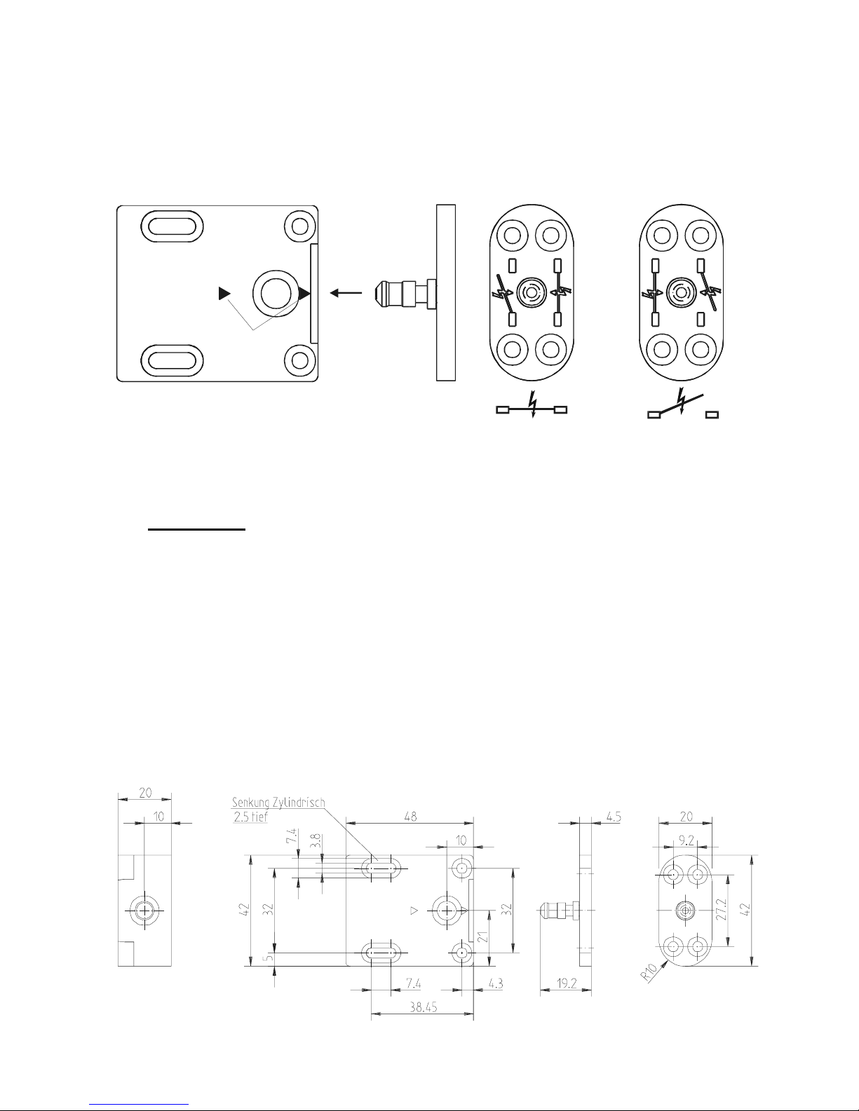
Funktionsprinzip:
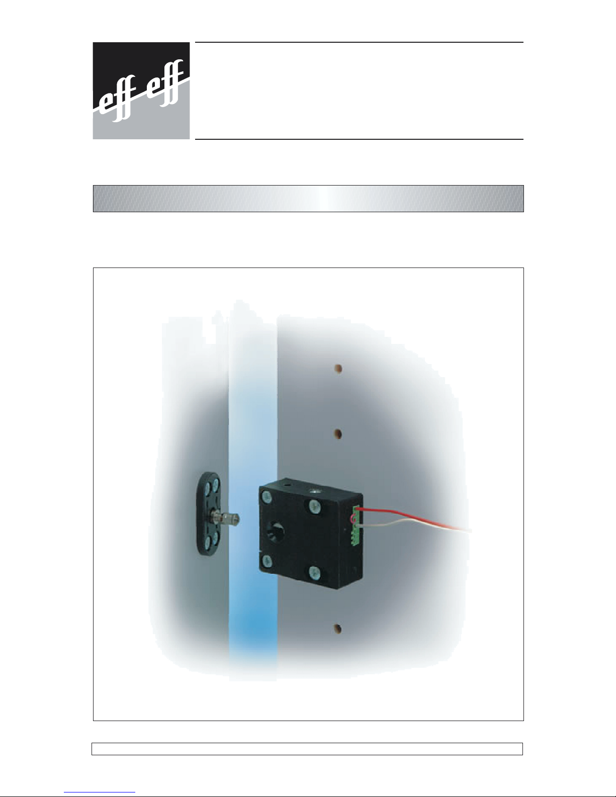
Die Kompaktverriegelung 1049.10/1049.10 RR besteht aus zwei Teilen. Teil 1
ist das Verriegelungselement, das z. B. am Seitenteil eines Schließfachs be-
festigt wird. Teil 2 ist die Rosette, die an der Tür befestigt wird.
Wird nun die Tür geschlossen, greift der
Verriegelungsbolzen der Rosette in das Ver-
riegelungselement ein und das Schließfach
wird verriegelt. Soll das Schließfach geöffnet
werden, mußzuerst das Verriegelungsele-
ment elektrisch entriegelt werden.
Je nach Anwendungsfall kann die Kompakt-
verriegelung so montiert werden, daßdie
Rosette entweder an der Stirnseite oder von
oben in das Verriegelungselement eingreift
(siehe Bild 1).
Verriegelungselement Rosette
Bild 1: Verriegelungsprinzip
4

Einstellen der Betriebsart Ruhe- oder Arbeitsstrom
Auf der Rosette sind die beiden Piktogramme für Ruhe- und Arbeitsstrom auf-
gedruckt (siehe Bild 2). Für die Betriebsart Ruhestrom mußdie Markierung auf
dem Verriegelungselement auf das Ruhestrompiktogramm der Rosette zeigen.
Entsprechendes gilt für die Betriebsart Arbeitsstrom, bei der die Markierung
auf das Arbeitsstrompiktogramm zeigen muß.
Montage
Montage- und Einstellarbeiten dürfen nur in der Rosettenausrichtung
Ruhestrom durchgeführt werden, falls die Kompaktverriegelung noch
nicht elektrisch entriegelbar ist. Die Tür oder die Schublade könnte
sonst nach dem Schließen nicht mehr geöffnet werden.
Das Verriegelungselement und die Rosette besitzen zur Befestigung jeweils
vier zylindrisch gesenkte Befestigungslöcher. Der Abstand entspricht dem
Möbelraster 32mm. Somit können die bestehenden Bohrungen, die für die
Fachmontage vorgesehen sind, für die Befestigung des Verriegelungsele-
ments verwendet werden. Reduzierhülsen, Schrauben und Unterlegscheiben
finden Sie beim mitgelieferten Befestigungsmaterial.
Die beiden Unterlegscheiben aus Edelstahl sind vor dem Festschrauben
unbedingt in die Langlöcher des Verriegelungselements einzulegen.
Maßzeichnung:
!
Markierung
Ruhestrom
Arbeitsstrom
Kompaktverriegelung Rosette
Bild 3: Maßzeichnung
(Maße in mm)
Bild 2: Rosettenausrichtung
5

Montagehinweise:
Bei der Montage sind das Verriegelungselement und die Rosette, wie in Bild 4
gezeigt, bündig zueinander auszurichten. Der Verriegelungsbolzen der Ro-
sette mußbeim Schließen der Tür bzw. Schublade ungehindert und vollstän-
dig in das Verriegelungselement eingreifen können. Ferner dürfen keine Zug-
kräfte seitens der Tür bzw. Schublade auf das Verriegelungselement wirken.
Die Rosette kann aufgeschraubt oder eingelassen montiert werden. Die Aus-
richtung von Verriegelungselement und Rosette erfolgt durch die Langlöcher
des Verriegelungselements. Als Positionierungshilfe für die Rosette wird eine
doppelseitig klebende Folie mitgeliefert, die auf die Rückseite der Rosette
aufgeklebt werden kann. Nach dem Aufkleben der Folie ist die Rosette in das
montierte Verriegelungselement mit der Ausrichtung Ruhestrom einzustecken
und die Tür zu schließen. Nach dem Öffnen der Tür klebt die Rosette an der
richtigen Stelle und kann für die Betriebsart Ruhestrom direkt montiert werden.
Für die Betriebsart Arbeitsstrom mußdie Rosette nach dem Anzeichnen der
Bohrungen noch um 180°gedreht werden.
Die Rosette darf keinesfalls wie in Bild 5 um 90°gedreht montiert werden.
Würde der Verriegelungsbolzen der Rosette so in das Verriegelungselement
eingreifen, ließe sich die Tür oder die Schublade nicht mehr öffnen.
Richtige Positionierung: Der Verriegelungsbolzen der Rosette kann ungehin-
dert und vollständig in das Verriegelungselement eingreifen.
Falsche Positionierung: Die Rosette greift um 90°verdreht in das Verriege-
lungselement ein.
!
Bild 4: Montagehinweis
Bild 5: Montagehinweis
6

Montagebeispiele:
Die Bilder 6 und 7 zeigen, wie die Kompaktverriegelung an einem Schreibtisch
mit Schubladen oder an einem Einbauschrank montiert werden kann.
Der Kompaktverriegelung liegt ein Zubehörbeutel bei. Dieser enthält Befesti-
gungsschrauben und Unterlegscheiben für Verriegelungselement und Rosette
sowie Reduzierhülsen für die Montage in vorhandene Fachbohrungen.
Bild 6: Anbau an einer Schublade
Schublade
Schublade
Unterleg-
scheibe Unterleg-
scheibe
Bild 7: Anbau bei einem Einbauschrank
mindestens 25 cm
7

Elektrischer Anschluß
Die Kompaktverriegelungen 1049.10 und 1049.10 RR müssen bei 100% Einschaltdau-
er mit einer stabilisierten 12 V oder 24 V Gleichspannung betrieben werden. Eine Ent-
riegelung durch Wechselspannung ist möglich, wird aber wegen des auftretenden
Brummgeräusches nicht empfohlen. Die Verschaltung ist nach Anschlußplan durchzu-
führen (siehe Bild 8). Die Drahtbrücken, für den Anschluß, sowie die Diode finden Sie
im Zubehörbeutel.
Die Ausführung 1049.10 RR besitzt zusätzlich einen potentialfreien Wechselkontakt,
der den Öffnungszustand der Tür überwacht.
Bei der Leitungsauswahl ist der Leitungsquerschnitt so zu wählen, daßdie Spannung
an der Kompaktverriegelung nach Abzug aller Verluste maximal 10% unter der ange-
gebenen Betriebsspannung liegt.
Anschlußplan
Vorgehensweise beim Anschluß:Schrauben der benötigten Klemmen durch Linksdrehen (3-4
Umdrehungen) öffnen. Leitung in die Klemme einführen. Klemme durch Rechtsdrehen schließen.
Technische Daten:
Betriebsart Ruhe- oder Arbeitsstrom Moment- und Dauerentriegelung
Betriebsspannung 12V GS stab. 12V WS
Brummgeräusch 24V GS stab. 24V WS
Brummgeräusch
Anschlußspannung Betriebsspannung ± 10%
Stromaufnahme typ. 260 mA 140 mA 130 mA 70 mA
Max. Belastbarkeit
des RR-Kontakts 25 V/ 1A
Zugfestigkeit 1000 N (≈100 kp)
Schutzart nach
DIN 40050 IP 20
Gehäusetemperatur Bei Dauerbestromung ca. 60°C
Temperaturbereich +10°C - +40°C
Maße in mm (L x B x H) Verriegelungsteil o. Rosette 48 x 42 x 20
Klemmen 5-7 nur
in der
RR Ausführung
Kontaktstellung:
zeigt “Tür offen”
Nur bei Gleichspannung!
Wird die Kompaktverriegelung an
einem elektronischen Gerät mit
Gleichspannung betrieben, muß
zusätzlich eine Freilaufdiode
parallel zur Spule angeschlossen
werden.
Diode im Zubehörbeutel
Bild 8: Anschlußmöglichkeiten
8

Cabinet Locks
Mounting and Installation Instructions
D0019604
1049.10
1049.10RR

10
Contents
General Description 11
Functional characteristics
Fail-unlocked and fail-locked operation 11
Setting of operating mode fail-unlocked or fail-locked 12
Mounting
Dimensioned drawing 12
Mounting instructions 13
Positioning of compact lock and rosette 13
Mounting examples 14
Drawer 14
Fitted cupboard 14
Electric supply
Connecting diagram 15
Technical data 15

General description
The compact locking units 1049.10 and 1049.10 RR have especially been
developed for the locking of furniture. They can be used instead of usual me-
chanical lockings or additionally as an access control system and prevent u-
nauthorized access to valuables or certain documents.
The compact locking units can be used for locking filing cabinets, fitted cupbo-
ards, drawers, post-office boxes / safe-deposit boxes and glass cabinets, for
example.
The most simple way to operate the access control system is by means of a
key switch. If it is necessary to electronically control, register and monitor the
access control system, the compact locking unit can be combined with a code
or card reader system.
The RR version additionally incorporates a change-over contact for monitoring
the state of the door (open/closed).
Taking into account the varied possibilities to use the compact locking unit, it
can be operated in the fail-unlocked mode as well as in the fail-locked mode.
The field reversibility is easily executed in no time during the installation of the
unit by positioning the rosette accordingly.
Due to the integrated mechanism that keeps the door closed, the door of
a filing cabinet, for example, is kept close even if it is unlocked. Conse-
quently, additional mechanisms for keeping the door closed (e.g. magne-
tic snaps) are not required.
Fail-unlocked and fail-locked operation:
The difference between the fail-unlocked and the fail-locked operating mode is
the following: the fail-unlocked version must be energized in order to be locked
whereas the fail-locked version must be energized in order to be unlocked.
Note:
Fail-locked operation means that in the event of power failure unlocking is
impossible and consequently the door cannot be opened.
Functional characteristics:
The compact locking unit 1049.10/1049.10 RR consists of two parts. Part 1 is
the locking element which is, for example mounted laterally to a safe-deposit
box. Part 2 is the rosette which is installed at the door.
When the door is closed, the locking bolt
of the rosette engages the locking ele-
ment and the safe-deposit is locked. If
the safe-deposit must be opened, the
compact locking element must be unlo-
cked electrically first.
According to the requirements, the com-
pact locking unit can be installed for front
or top engagement of the rosette (see
illustration 1).
Locking element Rosette
Or
Illustration 1: Locking principle
11

Setting of fail-unlocked or fail-locked operating mode
Two pictograms are printed on the rosette, one for fail-unlocked and one for
fail-locked mode (see illustration 2). For operation in the fail-unlocked mode,
the mark on the locking element must point to the fail-unlocked pictogram of
the rosette. For operation in the fail-locked mode, the mark must point to the
fail-locked pictogram.
Mounting
Mounting and adjustment only when the rosette is in the fail-
unlocked position in case the compact locking unit cannot yet be
unlocked electrically. Otherwise, it would not be possible to open the
door or the drawer any more.
Four cylindrically countersunk mounting holes each are provided for mounting
the locking element as well as the rosette. Position of mounting holes see
drawing. Reducing bushes, screws and washers are included in the mounting
material supplied.
Before fastening the two washers of special steel with screws, they must
be placed into the elongated holes of the locking element.
Dimensioned drawing:
!
rosette
Mark
fail-unlocked
Locking element
&\OLQGULFDOFRXQWHUVLQNLQJ
GHSWK
Illustration 2: Alignment of the rosette
Illustration 3: Dimensioned drawing
dimensions in mm
12

Mounting instructions:
Locking element and rosette must be aligned as shown in illustration 4 (flush).
When closing the door or drawer, the locking bolt of the rosette must be able
to engage the locking element unimpededly and completely. Furthermore, no
tensile force caused by the door respectively the drawer must act on the
locking element. The rosette can be fixed by screws and is also suitable for
flush mounting. The adjustment of locking element and rosette must be
effected by means of the elongated holes in the locking element. An adhesive
film (adhesive on both sides) is supplied which can be stuck to the back of the
rosette. This will help you to find the correct position of the rosette.
After fixing the adhesive film, the rosette must be put into the mounted locking
element with fail-unlocked setting and the door must be closed. When the door
is opened again the rosette sticks in the correct position. After marking the
drilling points, the rosette must be turned through 180°.
Under no circumstances must the rosette be mounted as shown in
illustration 5 i.e. turned through 90°. If the locking bolt of the rosette
engaged the locking element that way, it would not be possible to
open the door or drawer any more.
Correct positioning: The locking bolt of the rosette engages the locking ele-
ment unimpededly and completely.
Wrong positioning: The rosette turned - through 90°.
!
Or
Illustration 5: Mounting instruction
Illustration 4: Mounting instruction
13

Mounting examples:
Illustrations 6 and 7 show possibilities for mounting the compact locking unit to
a desk with drawers or to a fitted cupboard.
An accessories bag is supplied with the compact locking unit. This bag con-
tains fixing screws and washers for the locking element and the rosette as well
as reducing bushes for the installation in existing bore holes.
drawer
drawer
washer washer
minimum 25 cm
Illustration 6: Mounting to a drawer
Illustration 7: Mounting to a fitted cupboard
14

Electric Supply
With regard to continuous duty operation, the compact locking units 1049.10 and
1049.10 RR must be operated with stabilized DC, 12 V or 24 V. Unlocking by AC is
possible, however, it is not recommended due to the buzzing sound caused. Connecti-
ons must be effected according to the connecting diagram (see illustration 8). The
necessary jumpers as well as the diodes are included in the accessories bag.
Model 1049.10 RR additionally incorporates a change-over contact which monitors the
state of the door (open/closed).
When determining the wiring please take into consideration that the supply voltage –
measured at the terminals –is not lower than the minimum indicated.
Connecting Diagram:
Instructions for connection: loosen the screws of the required terminals by turning them antic-
lockwise (3-4 turns). Insert the lead into the terminal. For fastening the terminal retighten the
screws by turning them clockwise.
Technical data:
mode of operation fail-unlocked or fail-locked operation
momentary or continuous unlocking
operating voltage 12V DC stab. 12V AC
buzzing
sound 24V DC stab. 24V AC
buzzing
sound
connecting voltage operating voltage ± 10%
current consumption typ. 260 mA 140 mA 130 mA 70 mA
max.cap. of the RR contact 25 V/ 1A
tensible strength 1000 N (≈100 kp)
type of protection accor-
ding to DIN 40050 IP 20
housing temperature continuous energization: approx. 60°C
temperature range +10°C - +40°C
dimensions in mm (L x W x H) locking element w/o rosette 48 x 42 x 20
Terminals 5-7
only with
RR version
Contact position
shows
“door open”
* Only with DC!
If the compact locking unit is
operated at an electric device
with DC, an additional recovery
diode must be connected in
parallel to the coil.
Diode in accessories bag
Illustration 8: Possibilities of connection
15

effeff Fritz Fuss GmbH & Co.
Kommanditgesellschaft auf Aktien
Bildstockstraße 20
D-72458 Albstadt
Telefon +49 74 31/1 23-0
Telefax +49 74 31/1 23-240
www.effeff.com
info@effeff.com
An ASSA-ABLOY Group company
ASSA ABLOY
This manual suits for next models
1
Table of contents
Languages:
Other effeff Door Lock manuals
Popular Door Lock manuals by other brands

PortaPivot
PortaPivot STEALTHPIVOT PAP-LOCK Assembly & installation

Linear
Linear IEI DoorGard 212LS Series Installation & programming guide

JAKO
JAKO RD101CP installation guide

McGrathLocks
McGrathLocks ML ALBION user guide

Borglocks
Borglocks BL6100Mk4 Series instruction manual

Abus
Abus HomeTec Pro Fitting and operating instructions

Salto
Salto UBOX4000 installation guide

FUHR
FUHR multitronic 881 quick start guide

Glutz
Glutz Heso 59105 Fixing instructions

Kaba
Kaba SIMPLEX 5000 CYLINDRICAL installation instructions

Kaba
Kaba Simplex 1000 Series installation instructions

BRINKS
BRINKS Push Pull Rotate Installation & operation instructions