effeff 309X User manual
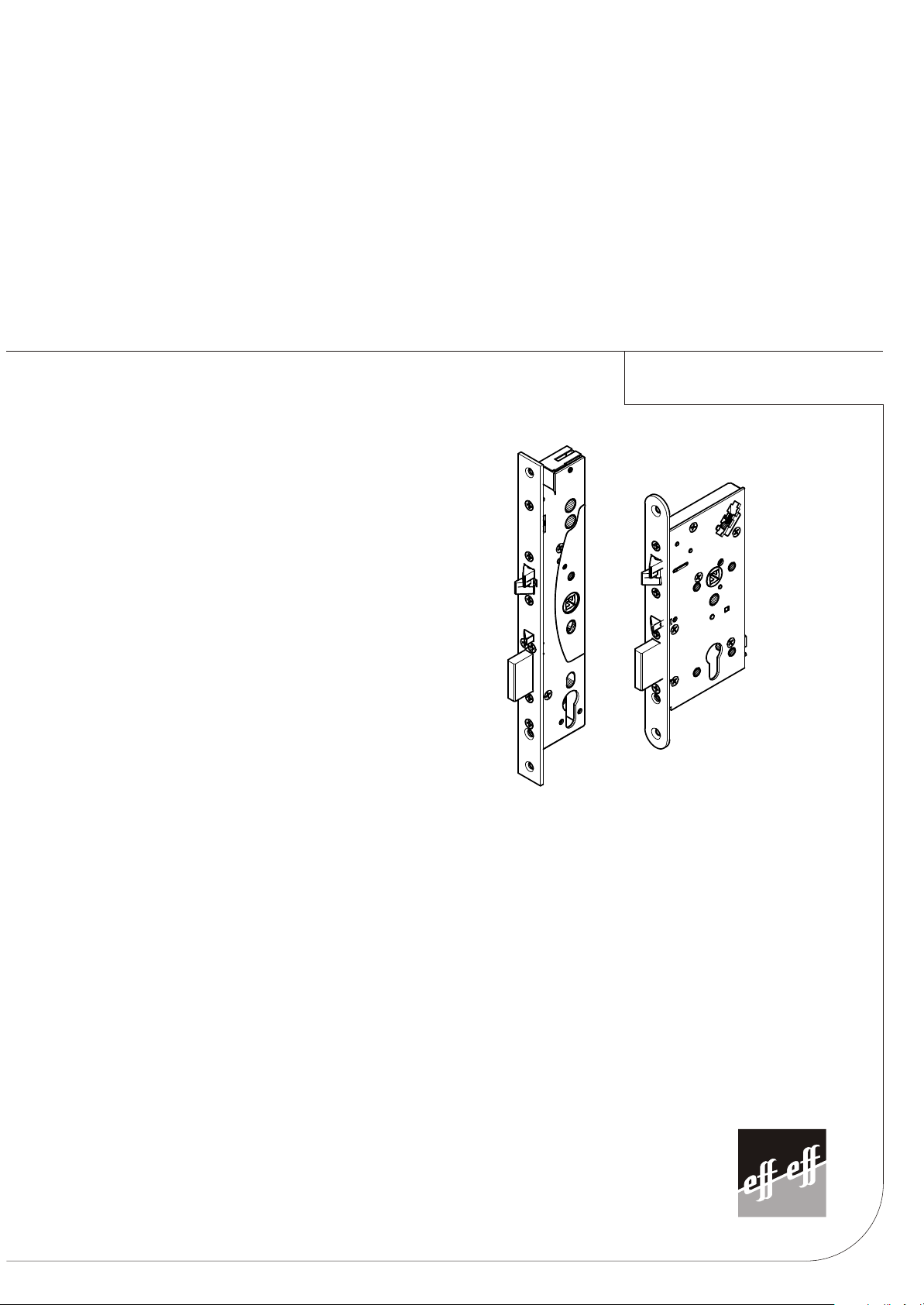
309X/409X/709X
D0035300
Sicherheitsschlösser
Serrature di sicurezza
Security locks
Cerraduras de seguridad
Serrures de sécuritéSerrures de sécurité


Contents
Technical Data............................................................................................................ 5
Standards ................................................................................................................... 5
Wiring Diagram ........................................................................................................... 5
Emergency Exit Devices – Installation According to EN 179...................................... 6
Panic Exit Devices – Installation According to EN 1125 ............................................. 7
Settable Functions of 709X (narrow style).................................................................. 8
Settable Functions of 709X (wooden door)................................................................. 9
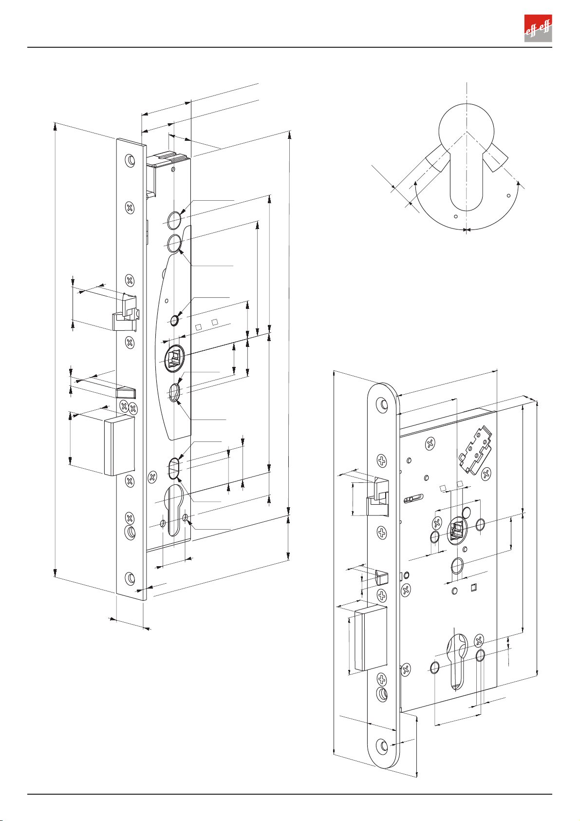
Drilling Scheme (Locks).................................................................................... 16 – 17
Drilling Scheme (Strike Plates for Wooden Door)..................................................... 18
Installation Schematic....................................................................................... 19 – 26
Inhalt
Technische Daten..................................................................................................... 10
Prüfungen ................................................................................................................. 10
Anschlussschema..................................................................................................... 11
Installation für Notausgang entsprechend EN 179 ................................................... 12
Installation für Anti-Panik-Ausgänge entsprechend EN 1125 ................................... 12
Einstellbare Funktionen 709X (Rohrrahmen)............................................................ 13
Einstellbare Funktionen 709X (Vollblatt)................................................................... 14
Bohrschema für Türdrückersteuerungen .......................................................... 16 – 17
Bohrschema für Schließbleche................................................................................. 18
Installationsskizzen............................................................................................ 19 - 26
3
20
22
10
8
6
35
3
9
8
/
33.7
55
/ 60
/ 65
8
Ø8
Ø6
Ø6
235
88
/
93
/ 98
16.5
38
38
168.5
21.5
66.5
20 / 2
72(PZ) / 7 (RZ)
Max 5
Max 5
Max 7
Ø10.5
Ø10.5
Ø5.5
Ø8.5
Ø5.5
Ø8
Ø8
Ø .5
20
15
21.8
16.9
92 (PZ) / 9 (RZ) 91
76
25
21.5
25
25
30
3
300
35
20
6
8
22
10
9
8 /
5 / 50 / 55 / 60
20.5
30 / 35 / 0 / 5
2
/ 28
4

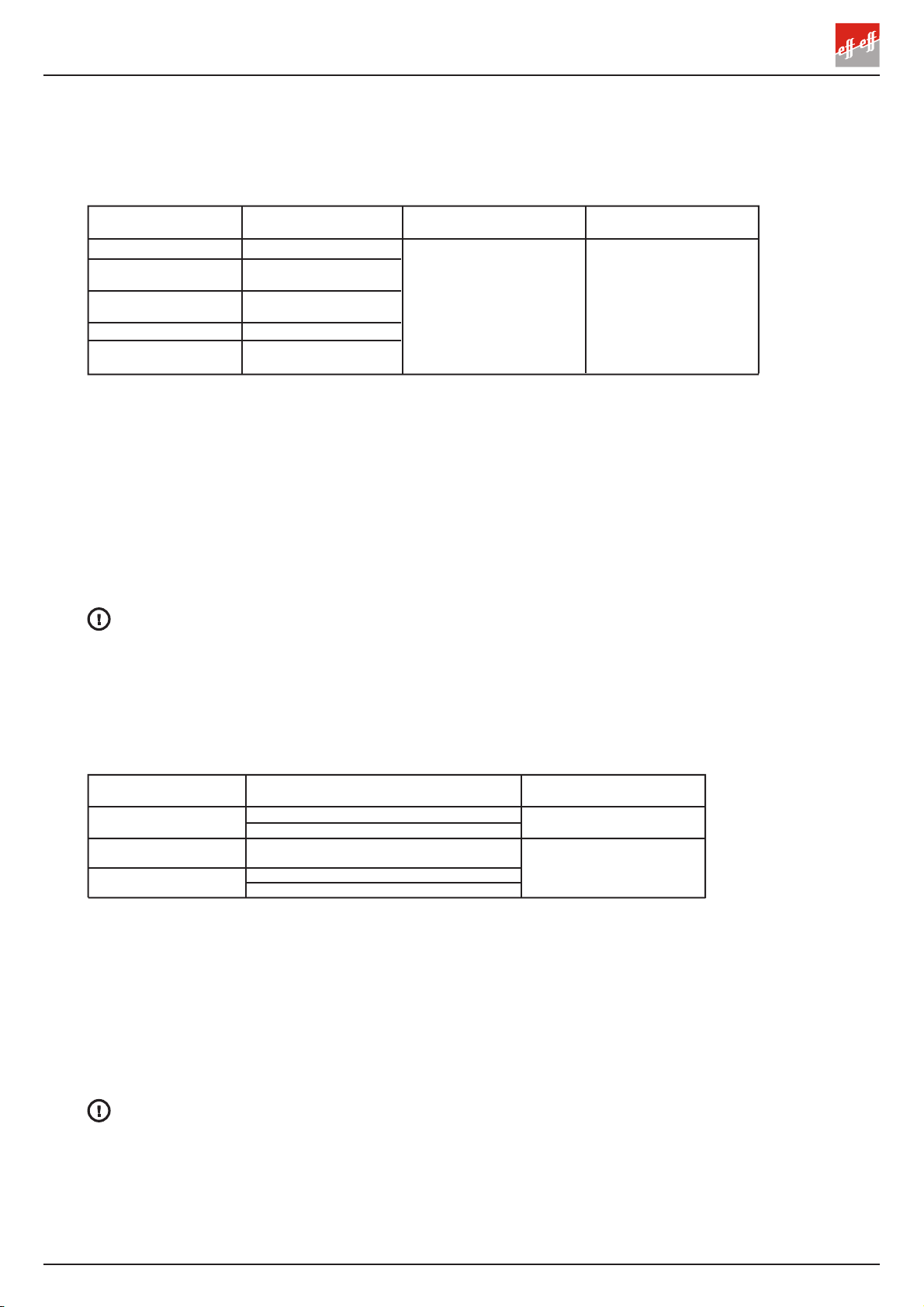
Operating voltage *) **):12 2 V DC STAB (-10%, +15%)
Current **):Max. 0. 0 A
Idle 0.13 A (12V DC)
0.065 A (2 V DC)
Micro switches **):Max. 0.5 A 30V AC/DC resist, 10 W
Operating temperature:-20°C - +60°C
Bolt throw:20 mm (deadbolt), 10 mm (double action bolt)
Backset:55, 60, 65 mm (wooden door)
30, 35, 40, 45 mm (narrow style)
Forend:20, 2 mm (wooden door)
2 , 28 mm (narrow style)
Spindle:9 mm (8 mm with snap spindle adapter)
Connection cable:Z09KAB (10 m) 16 x 0.1 mm2
Door clearance:2 - 5.5 mm
Settable functions:Mechanical functions:
- Opening direction of trigger bolt
- Exit handle side (709X)
Electrical function: *) **)
- Fail locked / Fail unlocked
Monitoring outputs **):Bolt deadlocked
Lock open
Trigger bolt in
Handle down
Cylinder used
Sabotage
Strike plate:Z09XSBL-01 ... Z09XSBL-04
*) Not micro switch locks
**) Not mechanical locks
TECHNICAL DETAILS
TESTED ACCORDING TO THE STANDARDS
EN 179 3 7 6 1 1 3 2 A Exit
EN 1125 3 7 6 1 1 3 1/2 A Panic exit
EN 163 -1 Fire
EN 61000-6-1:2001 EMC
EN 61000-6-3:2001 EMC
EN STANDARDS
ENGLISH
5
**) Potential free loop is closed when
connection cable is connected
to lockcase.
*) not micro switch locks
COMMON FOR BOLT OUT /
HANDLE DOWN /
KEY CYLINDER USED
12V DC (-10%) - 2 V DC (+15%) STAB.
*)
+
LOCKED / OPEN *)
HANDLE DOWN
BOLT OUT
BOLT IN
COMMON FOR BOLT IN /
TRIGGER BOLT IN
SABOTAGE LOOP **)
MONITORING OUTPUTS
White
Red
Blue
Turquoise
Violet
Orange
Yellow
Grey
Pink
Brown TRIGGER BOLT IN
KEY CYLINDER USED
Green/Red
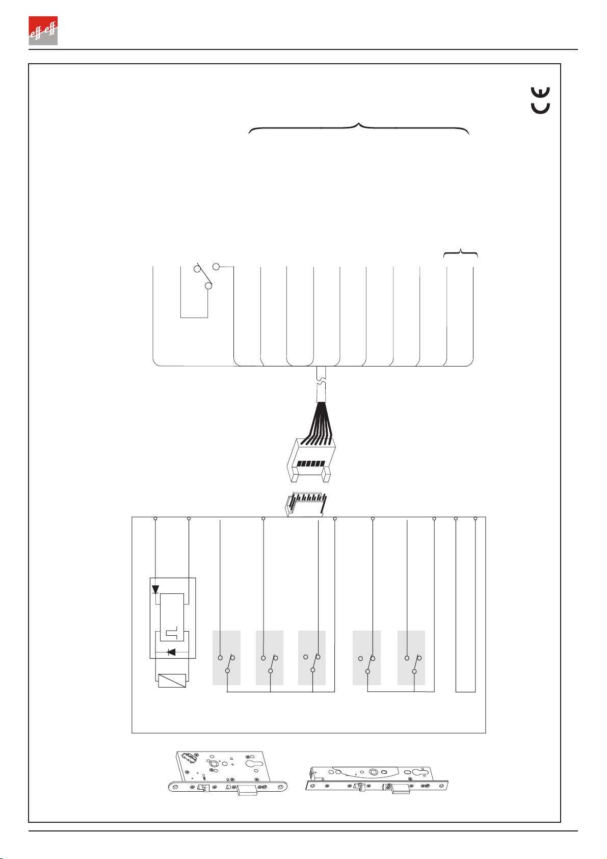
WIRING DIAGRAM
409X/709X
Connection cable
Length 10m 16 x 0.1 mm
2
Micro switches of lock case when:
- Key cylinder not used
- Handle not used
- Bolt out
- Trigger bolt in
- Bolt not in
(POTENTIONAL FREE CONTROL)
Lock case
Control
Unit
Solenoid
Red
White
+12 - 2 V DC
GND / Control
Orange
Yellow
Brown
Grey
Pink
Violet
Turquoise
Green/red
Blue
COMMON
KEY CYLINDER USED
HANDLE DOWN
BOLT OUT
TRIGGER BOLT IN
BOLT IN
COMMON
SABOTAGE LOOP
6
EMERGENCY EXIT DEVICES INSTALLATION ACCORDING TO EN 179
The following lock cases and handles are approved to be installed together in an emergency
exit door. Strike plate Z09XSBL-01 ... Z09XSBL-04 must be used in the installation.
EN 179
PANIC EXIT DEVICES INSTALLATION ACCORDING TO EN 1125
The following lock cases and push bars are approved to be installed together in a panic exit door.
Strike plate Z09XSBL-01 ... Z09XSBL-04 must be used in the installation.
R comm nd d distanc from a floor to a handl or to a push bar is b tw n
900mm - 1100mm.
Lubricat th bolts of th lock cas at l ast onc a y ar. Us vas lin typ lubrication.
Not ! effeff will not b liabl for products in cas th s instructions ar not follow d.
EN 1125
Functional ch ck aft r installation:
Emergency exit (active) side and functional sensitivity tests:
- Use the handle of exit side. Exit side is correctly set if the bolt goes inside the lock case
irrespective of the electrical control.
- In th profil door locks the force of handle is about 15 N (approximately 1.5 kg weight
at a 100 mm distance from the pivot of the handle opens the lock).
- In th wood n door locks the force of handle is about 25 N (approximately 2.5 kg weight
at a 100 mm distance from the pivot of the handle opens the lock). According to EN 179
the force of handle must be less than 70 N.
- Close the door slowly and check that the lock deadlocks.
- Check that the bolts slide freely into the strike plate.
Th saf ty f atur s of this product ar ss ntial to its complianc with EN 179. No
modification of any kind, oth r than thos d scrib d in th s instrictions, ar p rmitt d.
Functional ch ck aft r installation:
Panic exit (active)side and functional sensitivity tests:
- Push the push bar towards the door on the exit side. Exit side is correctly set if the bolt goes
inside the lock case irrespective of the electrical control.
- Force to open the lock by pushing the push bar is about 60 N (approximately 6kg). According
to EN 1125 it must be less than 80 N.
- Close the door slowly and check that the lock deadlocks.
- Check that the bolts slide freely into the strike plate.
Note! The length of the push bar must be at least 60 % of the width of the door.
Th saf ty f atur s of this product ar ss ntial to its complianc with EN 1125. No
modification of any kind, oth r than thos d scrib d in th s instrictions, ar p rmitt d.
effeff
DO 30.0 JPM
DO 30.05
8000-00-1100 (-), 8000-10-1100 (PZ)
8000-00-1100 (-), 8000-11-1100 (RZ)
NORMA 870000-30-0A
NORMA 870000-31-0A
NORMA 870000-32-0A
NORMA 870000-33-0A
Profil door locks
Wood n and m tal
door locks
8000-00-1100 (-), 8000-20-1100 (PZ)
8000-00-1100 (-), 8000-21-1100 (RZ)
effeff
DO 30.0
309X/409X/709X
309X/409X/509X
1016, 1023, 1052, 1056,
1070, 1080, 1088, 1090,
1117, 1118, 1119, 1137,
11 6, 1155, 1160, 1161,
1162, 1177, 1178, 1191,
0612, 0616, 0617, 0619,
0625, 0627, 0628, 06 6,
0662, 0665, 0680, 0681,
0682, 0688
309X/409X (narrow style)
IKON
DO 20.15.02 FSB
DO 20.03.01, DO 20.03.02 HEWI
DO 20.13.01, DO 20.13.02
Wood n and m tal
door locks
111, 111.23,
11 .23GK, 131, 132,
111X, 113X, 11 X,
161X, 163X, 171X,
112X, 165X, 166X
IKON
DO 20.15.01
Profil door locks
309X/409X (wooden door)
S6B3, S6B6
S6B8
S326, S 26, S K3
S K6
709X (narrow style)
709X (wooden door)
7

SETTABLE FUNCTIONS OF 709X (narrow style)
CHANGING THE FOREND Fig. A
1. Set the lock case forend up on the table.
2. Unscrew the fixing screws and remove the forend. Please note that the double action
bolt and its two bushings do not fall off.
3. Set another forend and screw in the screws. Use LOCTITE 2 3 on each fixing screw.
REMOVING THE MANIPULATION PROTECTION COVER Fig. B
Unscrew the fixing screws on the both sides of the lock case and remove the cover by pulling.
SETTING THE ELECTRICAL FUNCTION: FAIL LOCKED -> FAIL UNLOCKED Fig. C
(Needed tool: 1.5 mm Allen key)
The lock case is delivered in Fail locked mode:
Power off -> Handle does not open the lock.
Power on -> Handle opens the lock.
The lock case can be changed in Fail unlocked mode. Then the lock works electrically in the
following way:
Power off -> Handle opens the lock.
Power on -> Handle does not open the lock.
The electrical function is changed from Fail locked into Fail unlocked mode in the following way:
1. Remove the Allen screw from the right-hand hole (Fig. C1).
2. Screw in the Allen screw in the left-hand hole (Fig. C2). The Allen screw should settle
a little under the plastic edge, but please note not to use strength.
When the Allen screw is fixed in the right-hand hole, the electrical function is Fail locked.
When the Allen screw is fixed in the left-hand hole, the electrical function is Fail unlocked.
SETTING THE EXIT HANDLE SIDE Fig. D (Needed tool: 2.5 mm Allen key)
Exit side of the lock case is set with an Allen screw. The handle, of which side the Allen screw
is fixed, always opens the lock, while the handle of the other side is controlled electrically.
The lock case is delivered so, that the Allen screw is fixed on the caser side of the lock case.
Exit handle side can be changed in the following way:
1. Remove the Allen screw from the caser side of the lock case (Fig. D1).
2. Screw in the Allen screw in the corresponding hole on the other side of the lock case
(Fig. D2).
CHANGING THE HANDING OF THE TRIGGER BOLT Fig. E (Needed tool: 2.5 mm Allen key)
1. Locate the Allen key between the two springs in the back of the lock case in the Allen
screw-head of the trigger bolt (Fig. E1).
2. Loosen the Allen screw, so that the trigger bolt moves forward and can be turned around
(Fig. E2). Please note not to unscrew the Allen screw.
3. When the handing of the trigger bolt is set, tighten the Allen screw (Fig. E3).
When the needed settings have been done, attach the manipulation protection cover.
ATTACHING THE CABLE Fig. F
1. Unscrew the fixing screw and remove the cable clamp.
2. Connect the cable into the connector. Fix the cable clamp.
SETTING 8/9 SNAP SPINDLE ADAPTERS Fig. M
8/9 snap spindle adapters are set if the lock case is installed with 8mm spindle. The adapters
must be set on the both sides of the lock case.
There are two flat sides and two sides with a cup in a adapter. The round markings on the
handle follower of a lock case denote the direction, in which the adapter is set. With 309X
and 409X the direction of the adapter has to be noticed. With 709X the direction
has no significance.
8

SETTABLE FUNCTIONS OF 709X (wooden door)
CHANGING THE FOREND Fig. G
1.Unscrew the fixing screws and remove the forend.
2.Set another forend and screw in the fixing screws. Please note that a screw below the
dead bolt is longer than the other screws. Use LOCTITE 2 3 on each fixing screw.
SETTING THE ELECTRICAL FUNCTION: FAIL LOCKED FAIL UNLOCKED Fig. H
The lock case is delivered in Fail locked mode:
Power off -> Handle does not open the lock.
Power on -> Handle opens the lock.
The lock case can be changed in Fail unlocked mode. Then the lock works electrically in the
following way:
Power off -> Handle opens the lock.
Power on -> Handle does not open the lock.
The electrical function is changed from Fail locked into Fail unlocked mode by turning the
changer, which is located on the case side of the lock case, in the following way:
1. Unscrew the fixing screw and pull out the changer.
2. Turn the changer around.
3. Put the changer back and screw in the fixing screw. Please make sure that the changer
is straight and it fits tightly in the lock case.
When the arrows on the changer and the lock case are positioned as shown in the figure,
the electrical function is Fail locked (Fig. H1).
When the arrows on the changer and the lock case are positioned as shown in the figure,
the electrical function is Fail unlocked (Fig. H2).
SETTING THE EXIT HANDLE SIDE (709X, narrow style) Fig. I (Needed tool: 2.5 mm Allen key)
Exit side of the lock case is set with an Allen screw. The handle, of which side the Allen screw
is fixed, always opens the lock, while the handle of the other side is controlled electrically.
The lock case is delivered so, that the Allen screw is fixed on the case side of the lock case.
Exit handle side can be changed in the following way:
1. Remove the Allen screw from the case side of the lock case (Fig. I1).
2. Fix the Allen screw in the corresponding hole on the other side of the lock case
(Fig. I2).
CHANGING THE HANDING OF THE TRIGGER BOLT Fig. J (Needed tool: 2 mm Allen key)
1. Press the trigger bolt inside the lock case until the Allen screw of the trigger bolt is
shown on the cover side of the lock case.
2. Unscrew the Allen screw.
3. Pull out the trigger bolt and turn it around.
. Put the trigger bolt back in its place and press it inside the lock case.
5. Screw in the Allen screw.
SETTING MANIPULATION PROTECTION PLUG Fig. K
Set the brass plug on the outside of the lock case as shown in the figure.
ATTACHING THE CABLE Fig. L
1. Connect the cable into the connector.
2. Use a cable tie to fix the cable to the lock case. Cut the cable tie short.
SETTING 8/9 SNAP SPINDLE ADAPTERS Fig. M
8/9 snap spindle adapters are set if the lock case is installed with 8mm spindle. The adapters
must be set on the both sides of the lock case.
There are two flat sides and two sides with a cup in the adapter. The round markings on the
handle follower of a lock case denote the direction, in which the adapter is set. With 309X
and 409X the direction of the adapter has to be noticed. With EL560/EL561 the direction
has no significance.
9
Spannung *) **): 12 2 V DC (10 %, +15 %)
Strom**): 0, 0 A Spitzenstrom
0,13 A Ruhestrom bei 12V DC0,065 A Ruhestrom bei 2 V DC
Ausgänge Mikroschalter **): max. 30V AC/DC 0,8 A/20 W
Betriebstemperatur:20 °C bis +60 °C
Riegel:rechteckig, Hub 20 mm, Kreuzfalle, Hub 10 mm
Dornmaße: 55, 60, 65, mm (Vollblatt)
30, 35, 0, 5 mm (Rohrrahmen)
Stulpblech: 20, 2 mm (Vollblatt)2 , 28 mm (Rohrrahmen)
Abstand Türe/Zarge2 5,5mm
Drückernuss: 9 mm (8 mm mit Adapter)
Anschlusskabel:
(Z09XKAB) (10 m) 16 x 0.1 mm2
Einstellbare Funktionen Mechanisch:
- Einstellung der Steuerfalle (rechte, linke Türe)
- Einstellung der Panikseite (709X)
Elektrisch: *) **)
- Einstellung Arbeits- und Ruhestrom
Überwachung der Ausgänge **): Riegel ausgefahrenTüre geschlossen
Steuerfalle gedrücktDrücker betätigtSchließzylinder betätigtSabotage
Schließbleche:Z09XSBL-01 ... Z09XSBL-04
*) keine Schlösser mit elektronischer Überwachung
**) keine rein mechanischen Panikschlösser
DEUTSCH
TECHNISCHE DATEN
DIE SCHLÖSSER ENTSPRECHEN FOLGENDEN STANDARDS
EN 179 3 7 6 1 1 3 2 A
Notausgänge
EN 1125 3 7 6 1 1 3 1/2 A
Anti-Paniktüren
EN 163 -1
Feuerschutztüren
EN 61000-6-1:2001 EMC
EN 61000-6-3:2001 EMC
EN STANDARDS
10
Other manuals for 309X
1
This manual suits for next models
2
Table of contents
Languages:
Other effeff Door Lock manuals


