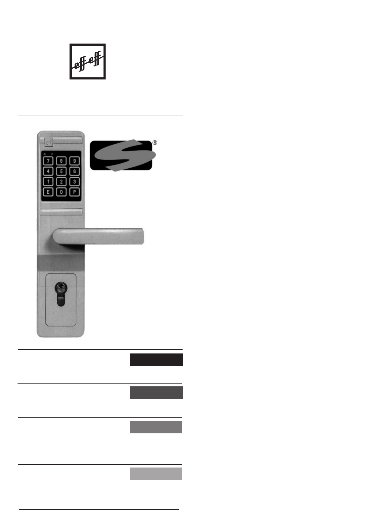
effeff 495-10 User manual
®
SICHERHEIT
UND PRÄZISION
français
MODE D'EMPLOI
ISTRUZIONI PER L'USO italiano
english
OPERATING INSTRUCTIONS
deutsch
BEDIENUNGS-ANLEITUNG
Seite 2
Page 7
Page 12
Pag. 17
Serrure
à combinaison
digitale
495-10 / 495-11
Code lock
495-10 / 495-11
Codeschloß
495-10 / 495-11
serratura
a combinazione
digitale
495-10 / 495-11
Türöffner-Systeme
Türsteuerungs-Systeme
D 00082

Lieber effeff- Kunde,
wir beglückwünschen Sie zu Ihrem Codeschloß und
danken Ihnen für das Vertrauen, das Sie mit Ihrer Wahl
dem Fabrikat effeff Fritz Fuss entgegenbringen. Wir sind
überzeugt, daß dieses Codeschloß Ihre Erwartungen
erfüllen wird.
Bitte lesen Sie unbedingt vor der Montage bzw. Inbetrieb-
nahme die allgemeinen Hinweise, damit Sie sich mit der
Handhabung des effeff-Codeschlosses vertraut machen
können. Richtige Handhabung und sachgemäße Pflege
sind die Voraussetzung für die hohe Lebensdauer und
ständige Betriebsbereitschaft des Gerätes.
Vorbereitung für die Codeschloßmontage
Da die Länge des Schließzylinders im vorhandenen Tür-
schloß für diesen Codeschloßbeschlag nicht mehr aus-
reicht, muß in der ersten Umbauphase zunächst ein pas-
senderSchließzylindereingebautwerden.UmdieSchließ-
zylinderlänge zu bestimmen, haben wir auf Seite 23 eine
Hilfsskizze abgebildet. Diese Schließzylinder (nicht im Lie-
ferumfangenthalten),lassensichdurchdenörtlichenFach-
handel besorgen.
DerCodeschloß-DrückervierkantistfürStandard-Türschlös-
sermit einer Türdrückernußvon 8 mmvorgesehen. Für die
Türdrückernuß-Maße8,5mmund9mmliegendemMonta-
ge-Zubehör spezielle Reduzierungshülsen bei.
Umrüstung an bestehenden Türen
Der Codeschloßbeschlag ist nur an Türen montierbar, de-
renSchlössereinDornmaßvonmindestens55mmaufwei-
sen (Seite 24).
VorhandeneBeschlägegarnitur,DrückervierkantundZylin-
derab-bzw.ausbauen. NeuenSchließzylinderausmessen
und einbauen (Skizze Seite 23).
Montage an neuen Türen
Standard-TürschloßmiteinemEntfernungsmaßvon72mm
und einem Dornmaß nicht unter 55 mm einbauen. Lauten
die Bestellangaben über ein anderes Entfernungsmaß, so
liegendemMontagezubehörentsprechendeZylinderplatten
bei.
Neuen Schließzylinder ausmessen und einbauen.
Das Codeschloß wird zunächst auf der, der endgültigen
Montageseite gegenüberliegenden Türblattseite, aufge-
steckt (Innenseite).
Bohrschablone an der Außenseite der Tür aufsetzen und
durchZylinder und Drückervierkantausrichten. Eine weite-
re Fixiermöglichkeit ist das Ausrichten durch die auf der
Schablone aufgedruckte Dornmaßeinteilung. Hierbei wird
beidemdurchdaseingebauteSchloßvorgegebenenDorn-
maß die entsprechende Dornmaßeinteilung auf der Scha-
2

Codeschloß Best.Nr. 495-10 495-11
Türblattstärken 38-50 mm 50-70 mm
Beschlag oben 2 St.M 5x55 2 St.M 5x80
Beschlag unten 2 St.M 5x45 2 St.M 5x65
3
blone abgeschnitten. Dadurch kann die Schablone exakt
auf der Tür ausgerichtet und mit Klebestreifen befestigt
werden. Bei überfälzten Türen muß die Breite des Über-
schlages beachtet werden.
Holztüren
Bohrpunkte markieren und danach Bohrschablone und
Codeschloß von der Tür entfernen. Direktes Durchbohren
der Tür mittels Holzbohrer Ø 10 mm für Codeschloß-
befestigungsschrauben M 5 und Ø 16 mm für das Batterie-
anschlußkabel (Seite 25).
Metalltüren
Bohrpunkte markieren und danach Bohrschablone und
Codeschloß von der Tür entfernen. Direktes Durchbohren
der Tür mittels Metallbohrer Ø 6 mm (lange Metallbohrer
verwenden, Seite 26).
Mit Aufschälbohrer an der Außenseite der Tür Code-
schloßbefestigungsbohrungenaufØ10mmaufweiten.Die
Bohrung für das Batterieanschlußkabel muß an der Tür-
innenseite sowie an der Türaußenseite auf Ø 16 mm auf-
geweitet werden.
BeiBlechtürendürfendie VerbindungsschraubenM5nicht
zufestangezogenwerden,dasichsonstdieTürimSchloß-
bereich verformen kann.
Fertigmontage
Aufsetzen des Codeschloß-Außenbeschlages
Aufsetzen des Codeschloß-Innenbeschlages
Verschrauben der Codeschloßbeschläge:
Jeder Verpackungseinheit liegen 4 x 2 Codeschloß-Be-
schlägeschrauben bei. Die Länge der Befestigungs-
schrauben orientiert sich nach der Türblattstärke und nach
dem bestellten Codeschloß-Typ.
Aufstecken und Verschrauben der Türdrücker
Bevor die beiliegenden 4 Kunststoffabdeckhüllen für die
Codeschloß-Montagebohrungen aufgesteckt werden, soll-
te das Codeschloß in Betrieb genommen werden (
siehe
Inbetriebnahme und Programmierung
).
Inbetriebnahme und Programmierung
VorderErstinbetriebnahmedeselektrischenCodeschlosses
muß ein 9 Volt Batterieblock in das Codeschloß eingesetzt
werden. Hierzu muß das Batteriefach seitlich am Innen-
deutsch
schild des Codeschlosses mit einem Schraubendreher ge-
öffnet werden, um die Batterie auf den Anschlußclip zu
stecken. Der Batterieblock ist nicht im Lieferumfang des
Codeschlosses enthalten.
Batterien die zur Auswahl stehen:
9 Volt Lithium-Batterieblock (Betriebszeit ca. 2 Jahre,
bei täglich ca. 15 Betätigungen)
9 Volt Standard-Batterieblock (Betriebszeit ca. 1 Jahr,
bei täglich ca. 15 Betätigungen)
9 Volt Akku-Block
Funktionsprüfung
Einschalten der Betriebsbereitschaft durch Betäti-
gung der Taste E auf der Folientastatur.
Die grüne LED-Anzeige blinkt zweimal kurz auf als Ein-
gabebereitschaftsanzeige.
Initialisierungscode O eingeben (werkseitige
Grundeinstellung, auch nach Geräte-Reset).
Die Tür bzw. der Türdrücker wird für 3 Sek. zur
Betätigung(zumÖffnenderTür)freigegeben.Währendder
Türentriegelungszeit kann der Türdrücker nur einmal betä-
tigtwerden.IstdieTürentriegelungszeitvon3Sek.abgelau-
fen,ohnedaß dieTürgeöffnet wurde, soistderTürdrücker
wieder verriegelt.
Sollte das Codeschloß nach der Programmierung
oder dem Batteriewechsel nicht ordnungsgemäß funktio-
nieren,somußderBatterieclipnochmalskurzzeitigvonder
Batterie abgezogen werden (kurzzeitige Trennung der
Stromversorgung). Führt dies nicht zum Erfolg, siehe unter
Störung-Reset
.
Programmierung mit Eingabezeitlimit
Bei der Programmierung ist unbedingt darauf zu achten,
daß nach jeder Betätigung einer Taste auf der Folien-
tastatur nicht länger als 5 Sek. verweilt werden darf.
Erstprogrammierung des Änderungscodes bzw. Neu-
festlegung des Änderungscodes nach einem Reset
Einschalten der Betriebsbereitschaft durch Betäti-
gung der Taste E auf der Folientastatur. Die grüne LED-
Anzeige blinkt zweimal kurz auf als Eingabebereitschafts-
anzeige.Initialisierungscode O eingeben.
Durch Drücken der Taste P Programmiermodus
einschalten.
Gewünschten Änderungscode über die Folien-
tastatur eingeben. Zur Auswahl steht eine beliebige Code-
zahl von mind. 2 bis max. 6 Codeziffern.
Durch Drücken der Taste P Eingabe bestätigen.
Beispiel: E O P 1234 P = Änderungscode E 1234
4

Neufestlegung des Änderungscodes
Einschalten der Betriebsbereitschaft durch Betäti-
gung der Taste E auf der Folientastatur.
Die grüne LED-Anzeige blinkt zweimal kurz auf als Ein-
gabebereitschaftsanzeige.
Aktuellen Änderungscode eingeben.
Durch Drücken der Taste P Programmiermodus
einschalten.
Gewünschten neuen Änderungscode über die
Folientastatur eingeben. Zur Auswahl steht eine beliebige
Codezahl von min. 2 bis max. 6 Codeziffern.
Durch Drücken der Taste P Eingabe bestätigen.
Beispiel: E 1234 P 4321 P = neuer Änderungscode
E 4321
Programmierung der Benutzercode
ZurBedienungdesCodeschlossesstehen3freiprogrammier-
bare Benutzercodes zur Verfügung. Die Festlegung erfolgt
durch die Plazierungsangabe 1, 2 oder 3 ( sehen Sie hierzu
unser Beispiel).
Die 1. Codeziffer der zu programmierenden Benutzercodes
darfaufkeinenFallmitder1.CodezifferdesÄnderungscodes
übereinstimmend programmiert werden.
Einschalten der Betriebsbereitschaft durch Betäti-
gung der Taste E auf der Folientastatur. Die grüne LED-
Anzeige blinkt zweimal kurz auf als Eingabebereitschafts-
anzeige.Aktuellen Änderungscode eingeben.
Durch Drücken der Taste P Programmiermodus
einschalten.
GewünschtePlazierungdesBenutzercodeseinge-
ben (Ziffer 1 = Erster Benutzercode).
Durch Drücken der Taste P Eingabe bestätigen.
Gewünschten Benutzercode eingeben. Zur Aus-
wahl steht eine beliebige Codezahl bis max. 6 Codeziffern.
Durch Drücken der Taste P Eingabe bestätigen.
Die Programmierung eines evtl. zweiten oder dritten
Benutzercodes muß nach dem vorgenannten Prinzip erfol-
gen (sehen Sie hierzu unser Beispiel).
Beisp.:
E 4321 P 1 P 78493 P = 1. Benutzercode E 78493
E 4321 P 2 P 539 P = 2. Benutzercode E 539
E 4321 P 3 P 7431 P = 3. Benutzercode E 7431
Bedienung des Codeschlosses (max. Eingabezeit 13 Sek.)
Einschalten der Betriebsbereitschaft durch Betätigung
derTaste E auf der Folientastatur. Die grüne LED-Anzeige blinkt
zweimal kurz auf als Eingabebereitschaftsanzeige.
Aktuellen Benutzercode eingeben (eine der drei pro-
grammierten Benutzercodes).
Die Tür bzw. der Türdrücker wird für 3 Sek. zur Betäti-
gung (zum Öffnen der Tür) freigegeben. Während der Türent-
riegelungszeitkannderTürdrückernureinmalbetätigtwerden.Ist
dieTürentriegelungszeitvon3Sek.abgelaufen,ohnedaß die Tür
geöffnet wurde, so ist der Türdrücker wieder verriegelt.
deutsch
5

6
Falscheingaben von Codezahlen - Sperrzeit 13 Sek.
WirdeinefalscheCodezahleingegeben,erfolgtkeine Frei-
gabe der Tür. Desweiteren wird die Folientastatur für 13
Sek. elektronisch gesperrt (Sperrzeit). Erst nach Ablauf
dieser Sperrzeit ist wieder eine komplett neue Eingabe
möglich (
siehe Bedienung des Codeschlosses
).
Batteriewechsel
BeiweitgehendverbrauchterBatteriekapazität(nochca.50
Betätigungen möglich), blinkt während der Türent-
riegelungszeit von 3 Sek. eine rote LED-Anzeige auf der
Folientastatur auf. Diese Anzeige weist den Nutzer/Betrei-
ber auf die Notwendigkeit eines umgehenden Batterie-
wechsels hin. Die gespeicherte aktuelle Codezahl bleibt
während des Batteriewechselvorgangs erhalten.
Störung-Reset
Für den Gerätestörfall oder bei Verlust der Codezahl be-
steht die Möglichkeit eines Geräte-Resets (beachten Sie
Seite 22). Hierzu muß der äußere Codeschloßbeschlag
abmontiert werden, um auf der Codeschloß-Rückseite
(Außenschild) einen Reset-Taster bedienen zu können.
Zunächst muß (bei angeschlossener Batterie) auf der Ta-
statur die E Taste gedrückt werden und anschließend
innerhalbvon13Sek.dervorgenannteReset-Taster.Nach
diesem Vorgang muß das Codeschloß wieder montiert
werden. Durch diesen Reset-Vorgang ist das Codeschloß
wieder auf die werkseitige Grundeinstellung programmiert.
Die weitere Bedienung wird im Abschnitt
Funktionsprüfung
erklärt.
Bitte beachten Sie:
Während der Codeeingabe
darf der Türdrücker des Codeschlosses nicht betätigt wer-
den.DieFolientastaturdesCodeschlossesdarfausschließ-
lichnurmanuellbetätigtwerden(aufkeinenFallmitGegen-
ständen wie z.B. Schlüssel, Schreibstiften etc.)
Pflegehinweise:
Das Codeschloß darf nur mit
einem feuchten Lappen und mit nichtkratzenden, milden
Putzmitteln gereinigt werden. Vermeiden Sie das Eindrin-
gen von Feuchtigkeit in die Codeschloßbeschläge.
Für das hier beschriebene effeff-Produkt
gelten die Garantiebedingungen der
Firma Fritz Fuss GmbH & Co., Albstadt
Technische Änderungen vorbehalten.

Dear effeff client,
Maywe congratulateyou on your codelockandthankyou
forthetrustyouhaveplacedineffeffFritzFussinselecting
this brand. We are convinced that this code lock will meet
your expectations. It is essential that you read the general
instructions prior to initial operation, in order that you are
able to familiarize yourself with the handling of the effeff
codelock.Correcthandlingandpropercareareprerequisites
foralongservicelifeandtheconstantoperationalreadiness
of the equipment.
Preparations prior to fitting the code lock
Asthe lengthof the lock cylinder in the existing door lock is
no longer sufficient for the code lock’s hardware, the first
conversionstepmustbetoinstallasuitablelockcylinder.As
an aid there is a sketch on page 23 for the purpose of de-
termining the lock cylinder’s length. These lock cylinders
(not supplied by us) are obtainable from your local lock
smith shop.
The code lock’s spindle for the handle is envisaged for
standard door locks with a follower width of 8 mm. Special
reduction bushes are enclosed with the installation
accessories for the follower width of 8.5 mm and 9 mm.
Inordertofittwo cylinder platestothecodelock8counter-
sunkheadscrewsM4x8mmareincludedwiththeinstallation
accessories.
Conversion of existing doors
Thecodelockhardwareisonlyfittabletodoorswhoselocks
have a backset of at least 55 mm (
see page 24 for further
details
).
Remove the existing hardware set, handle and cylinder.
Gauge and fit the new lock cylinders (
see page 23
).
Fitting to new doors
Fit a standard door lock with CTC-distance (center to
center) of 72 mm and a backset of not less then 55 mm. If
the ordering data specify a different CTC-distance,
appropriatecylinder platesareincludedwiththeinstallation
accessories.
Gauge and fit the new lock cylinder (
see sketch
).
Initiallyplacethekeyboardfurnitureontheinsideofthedoor
and place the drilling template on the outside of the door, in
order to align it by using the spindle of the handle and
cylinderholes.Anothermethodoffixtureisalignmentusing
the backset chart printed on the template. Using this select
the correct backset chart is suitable for your lock. Then cut
the template to this line. By doing this, the template is
alignable precisely with the door and lock
and fixable by means of adhesive tapes
( see sketch). Should the doors be
rebated doors the width of the rebate
or shiplap has to be taken into
consideration.
7
english
Wooden doors
Mark the drilling points and then remove the drilling tem-
plateandthecodelockfrom thedoor.Use wooddrillsof10
mm dia. for the M 5 fixture screws and of 16 mm dia. for
the battery connection cable (
see page 25 for furthe
r
de-
tails
).
Sheet metal and metal doors
Markthedrillingpointsandthenremovethedrillingtemplate
andthecodelockfromthedoor.Usemetaldrillsof6mmdia.
(
see page 26 for further details
).
Widen the fixture borings to 10 mm in diameter on the
outside of the door using a centre bit. The boring for the
battery connection cable has to be widened on the inside
and outside of the door to a diameter of 16 mm.
Inthecase ofsheetmetaldoorstheM 5joiningscrewsmay
not be overtightened, otherwise the door may be deformed
in the area of the lock.
Finished assembly
Fitting of the code lock’s outer furniture
Fitting of the code lock’s inner furniture
Screw connection of the code lock furnitures:
Each packing unit includes 4 x 2 hardware screws. The
length of the fixture screws is determined by the door leaf
thickness and the code lock type ordered.
Code lock ordering off 495-10 495-11
door leaf thickness 38-50 mm 50-70 mm
Furniture top 2 pcs. each 2 pcs. each
M 5 x 55 M 5x 80
Furniture bottom 2pcs. each 2 pcs. each
M 5x 45 M 5 x 65
Press-fit and screw connection of door handles
The code lock should be put into operation before the 4
plasticcoverbushessuppliedfortheinstallationboringsare
pressed on (
see initial operation and programming
).
Initial operation and programming
Prior to initial operation of the electronic code lock a 9 volt
battery block has to be inserted into the code lock. For this
purpose the battery compartment on the side of the inner
furniture of the code lock has to be opened using a
screwdriver,inordertopluginthebatteryviatheconnection
clip. The battery block is not supplied by us.
8

Batteries to choose from
9 volt lithium battery block (operating life approx. 2 year)
9 volt standard battery block ( operating life approx. 1 year)
9 volt accumulator block
Functional testing
Switching-on of operational standby mode by
actuating the key E on the membrane keypad.
ThegreenLEDindicatorwillflashonbrieflytwice,indicating
entry standby.
Enter code number O ( original ex-works setting,
also after an equipment reset).
The door handle is released for actuation for 3
seconds (in order to open the door). During the door
unlocking period the door handle can be actuated only
once.
Ifthedoorunlockingperiodof3secondshasexpiredwithout
the door having been opened, the door handle is relocked
If the code lock does not function properly subse-
quent to programming or a battery change, the battery clip
has to be disconnected from the battery again for a short
while (brief interruption of the power supply).
If this proves to be unsuccessful,
see Error reset
.
Programmingof the codenumber ( maximumentry time 13
secs.)
Programming with time limit
Please pay attention when programming numbers into the
system only 5 sec. is allowed between pressing (entering)
each digit. Failure to observe this will mean that you have
to start your programming again from the beginning.
Initial programming of the master code or reinitaline
master code after a reset.
Switching-on of operational standby mode by
actuating the key E on the membrane keypad.
ThegreenLEDindicatorwill flashonbrieflytwice,indicating
entry standby.
Enter initialisation code O .
Switch on programming mode
by pressing the key P .
Enter the mastercode (programming code) with a
minimum of 2 and maximum number of 6 digits.
Confirmentrybypressingthekey P andswitchoff
programming mode.
Example: E O P 1234 P = mastercode E 1234
english
9
Changing the master code
Thefirstdigitofausercodemustneverbeidenticalwiththe
first digit of the master code! Failure to observe this means
that a complete reset of all codes is necessary see "Error
reset". All programming has to be done again.
Actuate the system by pressing button E on the
key pad. The green LED will flash twice.
Enter the old master code.
Press button P to actuate programming mode.
Enter the new master code with a minimum of 2
and maximum number of 6 digits.
Confirm entry by pressing the button P . This
switches off the programming mode.
Entering the mastercode also opens the door and allows
access to the programming mode.
Example: E 1234 P 4321 P = newmastercode E 4321
Programming of user codes
The system can accept 3 additional codes besides the
master. Each user code is programmed into the system in
one of these programming slots 1P, 2 P or, 3 P.
Thefirstdigitofausercodemustneverbeidenticalwiththe
first digit of the master code! Failure to observe this means
that a complete reset of all codes is necessary see "Error
reset". All programming has to be done again.
Actuate the system by pressing button E on the
key pad. The green LED will flash twice.
Enter the old master code.
Press button P to actuate programming mode.
To enter the programming slot press either 1P…
2P…
3P…
Enter the desired code with a maximum of 6 digits.
Press button P and the code is accepted and
programming mode is switched off.
Programming of all the codes is done in the same manor.
Examples: E 4321 P 1 P78493 P =First usercode E 78493
E 4321 P 2 P 539 P =
Second usercode
E 539
E 4321 P 3 P 7431 P =Third usercode E 7431
Operation of the code lock
(maximum entry time 13 secs.)
Switching-on of operational standby mode by
actuating the key E on the membrane keypad.
TheegreenLEDindicatorwillflashonbrieflytwice,indicating
entry standby.
Entering one of the valid code numbers.
The door handle is released for 3 secs. For the
purpose of actuation (in order to open the door). During the
unlockingperiodthedoorhandlecanbeactuatedonlyonce.
10

11
Ifthe door unlocking time of 3 secs.has expiredwithout the
doorhaving beenopened,thedoorhandleisthenrelocked.
Erroneous entry of code numbers
disable time period 13 secs.
Ifawrongcodenumberisentered,releaseofthedoorisnot
effected.Furthermorethemembranekeypadiselectronically
disabled for 13 secs. ( disable time). Only once this disable
time has expired a completely new entry is possible again
(
see operation of the code lock
).
Battery change
If battery capacity has been more or less used up ( approx.
50 actuations left), a red LED indicator will blink on the
membrane keypad during the door unlocking period of 3
secs.Thisindicatoradvisestheuser/operatorofthenecessity
of an immediate battery change. The stored current code
number is retained during the battery change procedure.
Error reset
Intheeventofanequipmenterrororlossofthecodenumber
it is possible to reset equipment ( see page 22 for further
details). For this purpose the outer code lock furniture has
to be removed, in order to be able to operate the reset key
onthe rearside of the code lock (outer plate). In order to do
this, first of all (with battery connected) the E key on the
keypad has to be pressed and subsequently the afo-
rementioned reset key within 13 secs. By way of this reset
procedurethecodelockisagainprogrammedtotheoriginal
ex-workssetting.Forfurtheroperationdetailsonthissubject
see the section
Functional testing
.
Pleasetakenote:
Duringoperationthedoorhandle
of the code lock’s outer furniture must not be subjected to a
prior load. The membrane keypad of the code lock may be
actuated manually only ( under no circumstances using
articles such as keys, pens etc.).
Instructions on care:
The code lock may only be
cleaned
using a moist cloth with a mild, non-abrasive clea-
ning agent. Avoid moisture penetrating the code lock
furnitures.
The warranty conditions of the company Fritz Fuss GmbH
& Co., Albstadt are valid for the effeff product described
above.
Right reserved to effect technical changes.
english

12
Cher client effeff,
vous venez de faire l´acquisition d´une serrure à combi-
naison digitale et nous vous en félicitons. Nous vous re-
mercions de la confiance que vous nous témoignez en
choisissant un produit effeff Fritz Fuss. Nous ne doutons
pas qu´il vous donnera entière satisfaction.
Veuillez lire attentivement les remarques d´ordre général
avant de mettre le matériel en service. Vous apprendrez
ainsi à le connaître et son utilisation en sera facilitée.
Sachez qu´une manipulation correcte et un entretien
approprié sont des conditions essentielles pour garantir
le parfait fonctionnement du matériel.
Préparatifs pour le montage
La longueur du barillet en place dans la serrure n'étant pas
suffisantepouruneserrureàcombinaisondigitale,ilconvient
toutd‘abordderemplacerlebarillet.Pourdéfinirlalongueur
qui convient le mieux, reportez vous au croquis de la page
23. Ces barillets ne sont pas inclus dans la fourniture.
Veuillez en faire l‘acquisition dans un magasin spécialisé.
L‘axe de la poignée est prévu pour des serrures standard
avec un fouillot de 8 mm. Toutefois, avec des réducteurs
adéquats, il peut être monté sur des serrures avec dont le
fouillot est de 8,5 mm ou de 9,5 mm.
Mise en place de la plaquette de fixation dans la rosette à
l‘aidede8visnoyéesM4x8mm.Deuxplaquesdefixation
sont comprises dans la fourniture.
Montage sur portes déjà en place:
Le système ne peut être monté que sur des portes dont
l´entraxe barillet-tétière est d´au moins 55 mm (
voir le
croquis à la page 24
).
Démonter les rosettes en place, l´axe de la poignée et le
barillet.Prendrelesmesuresdunouveaubarilletetlemettre
en place (
voir le croquis à la page 23
).
Première phase du montage sur portes neuves:
Monteruneserrurestandardavecunentraxefouillot-barillet
de 72 mm et un entraxe barillet-tétière d‘au moins 55 mm.
Si la commande a été fait pour un entraxe fouillot-barillet
différent de 72 mm, deux plaquettes de fixation seront
comprises dans la fourniture.
Prendre les mesures du nouveau barillet et le mettre en
place.
Appliquertoutd‘abordlarosetteportantleclaviersurlaface
intérieuredubattantdelaporte(passurlecôtéoùilserafixé
définitivement).
Appliquer le gabarit de percage sur la face extérieure du
battant et le dégauchir en mettant en place le barillet et
l´axe de la poignée.
Marquer les endroits à percer.

Autre possibilité: La serrure étant en place et l‘entraxe
barillet-tétière étant donc donné, il suffit de découper le
gabarit de percage sur la ligne de référence correspondant
àl‘entraxebarillet-tétièreenplace.Ensuiteutiliserlegabarit
de percage ainsi dimensionné pour marquer les endroits à
percer.
Avantdepercer,retirerlarosetteportantleclavierainsique
le gabarit de percage. Selon le type de la porte (en bois ou
en métal), tenir compte des observations faites plus loin.
Dans le cas d‘une porte à feuillure, tenir compte du
recouvrement.
Portes en bois:
Percer la porte avec une mèche à bois de 10 mm pour les
visdefixationM5delarosetteàclavieretunemèchede16
mm de diamètre pour le câble de branchement de la pile
(voir le croquis à la page 25).
Portes métalliques:
Percer la porte avec un foret de 6 mm de diamètre (utiliser
depréféranceunelongueurmèche,voirlecroquisàlapage
26).
Avec une mèche à chanfrein, élargir à 10 mm de diamètre
les alésages de fixation pour la rosette à clavier, sur la face
extérieurdubattant.L‘alésagepourlecâbledebranchement
de la pile doit être élargi à 16 mm de diamètre sur les deux
faces du battant.
Ne pas serrer trop fort les vis M 5 pour ne risquer de
déformer la porte.
Dernière phase du montage
Poser la rosette extérieure portant le clavier.
Poser la rosette intérieure.
Visser les rosettes:
La fourniture comprend 2 x 4 vis de
fixation (4 vis par rosette). La longueur des vis dépend de
l‘épaisseurdubattantetdutypedelaserrureàcombinaison
digitale commandée.
Réf.Serrure à
combinason digitale: 495-10 495-11
Epaisseur de porte 38 - 50 mm 50 - 70 mm
En haut de la rosette 2 vis M 5 x 55 2 vis M 5 x 80
En bas de la rosette 2 vis M 5 x 45 2 vis M 5 x 65
Mettre les poignées en place.
Avant de poser les pastilles en matière plastique qui
recouvrent les vis, tester le fonctionnement de la serrure à
combinaison digitale (
se reporter au mode d‘emploi et de
programmation
).
français
13
Mode d‘emploi et de programmation
Mettreenplaceunepilede9Vdanslelogementprévuàcet
effet sur le côté de la rosette intérieure qui est à ouvrir à
l‘aide d‘un tournevis. Presser sur la pile pour l‘engager
correctementsurlebornieràclip.Lapilen‘estpascomprise
dans la fourniture.
Piles utilisables:
Pile de 9 V au lithium (durée de vie: 2 ans environ, à
raison d'environ 15 sollicitations par jour)
Pile de 9 V standard (durée de vie: 1 an environ, à
raison d'environ 15 sollicitations par jour)
Bloc accu 9 V
Test de fonctionnement
Mise en service par pression de la touche E sur le
clavier.La LEDverteclignotebrièvementdeuxfoisdesuite,
signalant que le système est prêt à recevoir des données.
Taper le code O (Etat de base réglé à l‘usine et
retrouvé après un Reset)
La porte est libérée pour une durée d‘environ 3
secondes. Pendant cette durée, la poignée ne peut être
actionnée qu‘une seule fois. Si les 3 secondes se sont
écoulées sans que la porte ait été ouverte, la poignée se
retrouve verrouillée.
Si le fonctionnement n‘est pas assuré après la
programmation ou après un changement de pile, sortir la
pilepuislaremettreenplacedanslebornieràclip(interruption
brève de l‘alimentation électrique).
Si cette mesure ne suffit pas pour remettre le système en
fonctionnement, il faudra faire un Reset (
se reporter à
l‘explication donnée pour le Reset en fin de document
).
Programmationaveclimitationdutempsd'intervention
S'assurer pendant la procédure de programmation, qu'il ne
s'écoulepasplusde5secondesaprèslafrapped'unetouche.
Première mise en place du code d'accès à la
programmation ou redéfinition du code d'accès à la
programmation après un Reset.
Mise en service par pression de la touche E sur
le clavier. La LED verte clignote brièvement deux fois de
suite, signalant que le système est prêt à recevoir des
données.
Taper le code d'initialisation O
Presser la touche P pour passer en mode de
programmation.
Composer sur le clavier le code d'accès à la
programmation qui a été choisi: au choix un nombre
quelconque à 6 chiffres maximum.
Presser une nouvelle fois la touche P pour con-
firmer la saisie.
Exemple: E O P 1234 P =code d'accès
àlaprogrammation E 1234
14
Redéfinition du code d'accès à la programmation
Mise en service par pression de la touche E sur
le clavier. La LED verte clignote brièvement deux fois de
suite, signalant que le système est prêt à recevoir des
données.
Taper le code d'accès à la programmation actuel.
Presser la touche P pour passer en mode de
programmation.
Composer sur le clavier le nouveau code de
programmation qui a été choisi: au choix un nombre
quelconque de 2 chiffres minimum à 6 chiffres maximum.
Presserunenouvellefoislatouche P pourconfirmer
la saisie.
Exemple: E 1234 P 4321 P = nouveau code d'accès à
laprogrammation E 4321
Programmation du code d'accès
Ilestpossibledeprogrammertroisdifférentscodesd'accès
qui permettent d'ouvrir la porte. Cette programmation des
codes 1, 2 et 3 est à faire selon les explications suivantes.
Veiller attentivement à ce que le 1
er
chiffre du code d'accès
de la porte ne soit pas identique au 1
er
chiffre du code
d'accès à la programmation.
Mise en service par pression de la touche E sur
le clavier. La LED verte clignote brièvement deux fois de
suite, signalant que le système est prêt à recevoir des
données.
Taper le code d'accès à la programmation actuel.
Presser la touche P pour passer en mode de
programmation.
Précisersurle clavier lenumérodu code d'accèsà
programmer (chiffre 1 = premier code d'accès).
Presser la touche P pour confirmer le choix.
Composeralors surle clavierle code d'accès qui a
été choisi: un nombre quelconque de 6 chiffres maximum.
Presserunenouvellefoislatouche P pourconfirmer
la saisie.
Pour programmer le second et le troisième codes d'accès,
procéderselonleprincipedécritci-devantetconformément
à l'exemple ci-après.
Exemple:E 4321 P 1 P78493 P = premier code d'accès
E 78493
E 4321 P 2 P 539 P = second code d'accès
E 539
E 4321 P 3 P 7431 P = troisème
code d'accès
E 7431
15
français

16
Ouverture de la porte
(durée max. pour composer le code: 13 secondes)
Mise en service par pression de la touche E sur
le clavier. La LED verte clignote brièvement deux fois de
suite, signalant que le système est prêt à recevoir des
données.
Taper le code d'accès en vigueur (l'un des trois
codes programmés).
La porte est libérée pour environ 3 secondes.
Pendant cette durée, la poignée ne peut être actionnée
qu‘uneseulefois.Siles3secondessontécouléessansque
la porte soit ouverte, la poignée est reverrouillée
automatiquement.
Composition d'un faux code:
clavier bloqué pendant 13 secondes
Si l‘on tape un faux code, la porte ne sera pas libérée et le
clavierserabloquéélectroniquementpendant13secondes.
Après ces 13 secondes, il est de nouveau possible de
renouvelerlatentatived'accès(conformémentàlaprocédure
précisée plus haut sous le titre "Ouverture de la porte".
Changement de pile
Lorsquecommenceàsedécharger,uneLEDrougeclignote
sur le clavier pendant le déverouillage de la gâche. On sait
alors que la capacité de la pile est encore suffisante pour
ouvrir environ 50 fois la porte. Il convient de changer la pile
entempsvoulu.Le code enmémoireestconservépendant
l‘échange de la pile.
Dérangement - Reset
En cas de dérangement ou bien si l‘on a oublié le code, on
peut faire un Reset (cf. page 22 ). A cette fin, démonter le
couvercleexterne duboîtier,pouraccéderauboutonReset
sur la face postérieure du boîtier. Presser tout d'abord la
touche E (batterie raccordée), puis dans les 13 secondes
quisuiventpresserlatoucheReset.Dèsquecetteopération
est terminée, il convient de remettre le couvercle du boîtier
en place. Le Reset réinitialise la serrure à combinaison
digitale, autrement dit la ramène à l'état de programmation
initial (programmation usine). Se reporter au chapitre "Test
de fonctionnement" pour suite à donner.
A observer:
Ne pas actionner la poignée de la
porte pendant que l'on compose le code sur le clavier.
Presser les touches uniquement du bout des doigts (en
aucun cas avec une clé, un stylo ou autre objet similaire).
Entretien: Pour nettoyer le clavier, se servir d‘un
chiffonmouilléetd‘unproduitdenettoyagenondoux.Eviter
tout infiltration d'eau dans le boîtier.
La serrure à combinaison digitale est
garantie selon les conditions
générales effeff.
Sous réserve de modification techniques!

17
italiano
Caro cliente effeff,
Avete fatto indubbiamente un ottima scelta: un sistema di
controllo della porta a tastiera digitale effeff è una
garanzia di qualità e siamo certi ne rimarrete soddisfatti.
Leggete attentamente le istruzioni generali, l’istallazione
e l’uso saranno estremamente facili.
Una buona manutenzione garantisce un perfetto
funzionamento del prodotto.
Consigli per l’istallazione
La lunghezza del cilindro profilato esistente sulla Vs. porta
non sarà sufficiente per piazzare la serratura a codice
digitale. Per definire la lunghezza del cilindro profilato
vedereapag.23.L’acquistodiunnuovocilindrodisicurezza
potrà essere fatto presso un rivenditore specializzato.
L’interassedella maniglia è previsto per serrature standard
Italiane con q.8.
Per un perfetto assemblaggio delle bocchette alle placche,
sono in dotazione 8 viti M 4 x 8 mm.
Istallazione su porte esistenti
Il sistema serratura a codice effeff può essere montato su
porte con entrata minima di 55 mm. Le bocchette vengono
fornite standard in Italia per un interasse di 85 mm.
Smontare le maniglie ed il cilindro esistenti, prendere le
misure per il nuovo cilindro di sicurezza, forare come da
istruzioni a pag. 23/24, montare il nuovo cilindro, applicare
le placche del sistema a codice. La Vs. vecchia serratura è
diventata un sistema di controllo accessi a codice digitale.
Istallazione su porte nuove.
Montareunaserraturastandarddibuonaqualitàconentrata
minima55mmeconuninterassecompresofra72e92mm.
Nell’ordinareilsistemaacodicedigitale,precisarelamisura
interassedellaserratura.InItalialaforniturastandard è per
serrature con interasse mm 85.
Prendere le misure per la lunghezza del cilindro profilato.
Istallare la serratura standard con le consuete dime,
accertandosi dell’esatta foratura dell’interasse quadro
maniglia / cilindro profilato ed entrata cilindro.
Nelcasodiportericoperte,tenercontodellospessoredella
ricopertura.

18
Porte in legno:
Forare con una punta da legno da 10 mm per le viti di
fissaggio da 5 MA e con una punta da 16 mm par il cavo di
collegamento al vano batteria (vedi pag. 25)
Porte metalliche
Forare con una punta per metallo da 6 mm. Con uno
alesatore svasare i fori solo nella parte esterna della porta
finoa 10mm. Per il foro del cavo batteria, svasare fino a 16
mm su entrambi i lati della porta (vedi pag. 26).
Non serrare fortemente le viti da 5 MA per evitare di
deformare la porta.
Ultima fase di montaggio
Applicare sul lato esterno la placca con tastiera. Applicare
la placca contenente il vano batterie all’interno. Avvitare le
placcheconlevitidifissaggiocompresenelset.Lalunghezza
delle viti in dotazione dipende dallo spessore porta e in
dipendenzadaciòordinatel’articoloesattocomedatabella.
Articolo della serratura
a combinazione digitale: 495-10 495-11
Spessore porta 38 - 50 mm 60 - 70 mm
Viti parte superiore
della placca 2 pz 5 MA x 55 2 pz 5 MA x 80
Viti parte inferiore
della placca 2 pz 5 MA x 45 2 pz 5 MA x 65
Inserire e fissare l’impugnatura maniglia.
Primadiapporelecopertureinplasticasullevitidifissaggio,
controllareilcorrettofunzionamentodellaserraturaacodice
digitale,aportaaperta(
vediistruzionidiprogrammazionee
d’utilizzo
).
Istruzioni di programmazione e di utilizzo
Per l'utilizzo della serratura a codice va usata una pila a 9
Volt. Inserire una pila nel vano batteria apribile tramite un
cacciavite.Premerebenelapilanellasuasede.(Lapilanon
è compresa nel set)
Pile consigliate:
Pile a 9 V alcaline (durata di circa 2 anni per una
funzione giornaliera di circa 15 azionamenti)
Pile a 9 V standard (durata di circa 1 anno per una
funzione giornaliera di circa 15 azionamenti)
Accumulatore a 9 Volt

19
italiano
Prova di funzionamento
Premere il tasto E sulla tastiera. Il LED verde si
illumineràbrevementeduevoltediseguitosegnalando che
il sistema è pronto a ricevere i comandi
Premereiltasto O (Situazionedipartenzainstato
di Reset stabilito in fabbrica)
La porta è apribile per un tempo di circa 3 secondi.
Durantequestotempolamanigliapuòessereazionatauna
sola volta. Trascorsi i 3 secondi senza che la porta venga
aperta, la maniglia è di nuovo bloccata.
Se dopo la programmazione od il cambio di pila la
serratura non funzionasse perfettamente, togliere la pila e
rimetterla correttamente nella sua sede.
Sequestoaccorgimento nonbastasseperilfunzionamento
del sistema bisognerà procedere ad un Reset.
(Vedi
spiegazioni relative al Reset della serratura a codice)
Digitazione in tempo limitato
Nelladigitazionefareattenzioneche,traladigitazionediun
tastoel'altronondevonopassarepiùdi5secondi,altrimenti
si deve rifare l'intero codice.
Prima programmazione del codice master - nuova
determinazione del codice master
Premere il tasto E sulla tastiera. Il LED verde si
illumineràbrevementeduevoltediseguitosegnalando che
il sistema è pronto a ricevere i comandi.
Premere il tasto O (Situazione di partenza).
Premereiltasto P einserireilmododiprogramma.
Digitaresullatastierailcodicedesiderato.Scegliere
qualsiasi numero e formare il codice per un massimo di 6
cifre. Premereiltasto P econfermareleindicazionidate.
Esempio: E O P 1234 P = E 1234
Nuova determinazione del codice master
Premere il tasto E sulla tastiera. Il LED verde si
illumineràbrevementeduevoltediseguitosegnalando che
il sistema è pronto a ricevere i comandi.
Inserire il codice attuale.
Premereiltasto P einserireilmododiprogramma.
Digitaresullatastierailcodicedesiderato.Scegliere
qualsiasi numero e formare il codice che può avere da un
minimo di 2 a un massimo di 6 cifre.
Premereiltasto P econfermareleindicazionidate.
Esempio: E 1234 P 4321 P = Nuovo codice E 4321

Programmazione del codice degli utilizzatori
Per l'utilizzo della serratura a codice ci sono a disposizione
3 codici programmabili. La determinazione si effettua
attraversol'indicazionedeicollocamenti1,2o3(vedinostri
esempi qui sotto).
La 1. cifra del codice utente da programmare non deve
corrispondere in nessun caso alla 1. cifra del codice di
modifica.
Premere il tasto E sulla tastiera. Il LED verde si
illumineràbrevementeduevoltediseguito segnalando che
il sistema è pronto a ricevere i comandi.
Inserire il codice attuale.
Premereiltasto P einserireilmododiprogramma.
Inserire il collocamento dell'utilizzatore desiderato
(cifra 1 = primo codice del primo utilizzatore).
Premereiltasto P econfermareleindicazionidate.
La programmazione di uno e eventualmente di due o tre
codici degli utilizzatori deve essere eseguito secondo il
principio sopracitato (Vedi nostro esempio qui sotto).
E4321 P 1 P78493 P = Primocodicedell'utilizzatore E78493
E4321 P 2 P 539 P = Sec. codice dell'utilizzatore E 539
E4321 P 3 P 7431 P = Terzocodicedell'utilizzatoreE 7431
Apertura della porta
Premere il tasto E sulla tastiera. Il LED verde si
illumineràbrevementeduevoltediseguito segnalando che
il sistema è pronto a ricevere i comandi
Digitare il nuovo codice appena programmato (uno
dei 3 codici programmati).
La porta è apribile per un tempo di circa 3 secondi.
Durantequestotempolamanigliapuòessereazionatauna
sola volta. Trascorsi i 3 secondi senza che la porta venga
aperta, la maniglia è di nuovo bloccata.
Imputazione di un codice errato
Se viene digitato un codice falso/errato, la porta non può
essereapertaelatastierarimanedisabilitataper13secondi.
Trascorso questo tempo si può ricomporre il codice.
Cambio della pila
Quando la pila si sta scaricando, il LED rosso lampeggia
sulla tastiera durante l’apertura. Conviene predisporre il
cambio della pila al più presto. Il LED rosso inizia a
lampeggiare quando si ha ancora potenza per effettuare
circa 50 aperture.
20
This manual suits for next models
1
Table of contents
Languages:
Other effeff Lock manuals


Popular Lock manuals by other brands

Alarm Lock
Alarm Lock PDL3300 Specifications

Sygonix
Sygonix 1559246 operating instructions

Sewosy
Sewosy EF300 installation instructions

Assa Abloy
Assa Abloy 421-30-10 Installation and operating instructions

Igloohome
Igloohome Smart Keybox 3 Installer/user guide

Igloohome
Igloohome Smart Keybox 3 Installer/user guide


