Efka dc 1500 User manual

CONTROL AB286A5400
INSTRUCTION MANUAL
No. 402280 English
FRANKL & KIRCHNER EFKA OF AMERICA INC. EFKA ELECTRONIC MOTORS
GMBH & CO KG SINGAPORE PTE. LTD.
AB286A5400
KL2341
www.promelectroavtomat.ru


EFKA AB286A54003
CONTENTS Page
1IMPORTANT SAFETY INSTRUCTIONS 5
2RANGE OF APPLICATIONS 6
2.1 USE IN ACCORDANCE WITH REGULATIONS 6
3COMPLETE DRIVE UNIT CONSISTING OF 6
3.1 SPECIAL ACCESSORIES 6
4STARTING SERVICE 7
5SOCKET CONNECTORS 7
6CONNECTION DIAGRAM 8
7INTERFACE DEFINITION 11
7.1 BAUD RATE SELECTION 11
7.2 PROTOCOL 11
7.3 TRANSMIT TIMEOUT BEFORE “NAK“ 11
7.4 BYTE TO BYTE TIMEOUT 11
7.5 COMMUNICATIONMONITORING (SYSTEM VALUES D, GROUP E) 12
7.6 CONTROL CHARACTERS 12
7.7 SPECIAL CHARACTERS 12
7.8 DATA LINK ESTABLISHMENT 12
7.9 RTS 12
7.10 TEXT 12
7.11 STOP INPUT 13
7.12 ERROR OUTPUT 13
8PARAMETERS 13
8.1 SPECIAL FEATURES 17
8.2 BIT DESCRIPTIONS 17
8.2.1 “RDY“ BIT 5 IN STATUS BYTE 117
8.2.2 “NPE“ BIT 6 IN STATUS BYTE 118
8.2.3 “P1E, P1A, P2E, P2A, P3E, P3A“ IN STATUSBYTE 218
8.2.4 “PSYN“ BIT 7 IN STATUS BYTE 118
8.2.5 “P2T“ BIT 0 IN CONTROL BYTE 218
8.2.6 “2N“ BIT 1 IN CONTROL BYTE 218
8.2.7 “ZSTP_“ BIT 2 IN CONTROL BYTE 218
8.2.8 “PNLIM“ BIT 5 IN CONTROL BYTE 218
8.3 FUNCTIONAL DESCRIPTIONS 18
8.3.1 STOP SEGMENT ANGLE FOR POSITIONING (SYSTEM -VALUES C, GROUP 7) 18
8.3.2 RUN-OUTANGLE FOR POSITIONING (SYSTEMVALUES D, GROUP E) 19
8.3.3 ACCURATE POSITIONING 19
8.4 TABLE OF PARAMETERS 20
9ASCII DATA TRANSFER21
10 LIST CALL 21
11 INTERRUPT CONTROL 23

EFKA AB286A5400
4
CONTENTS Page
12 EXAMPLES FOR SERIAL DATA TRANSFER 24
12.1 POWER ON24
12.2 OPERATION 24
13 POSITION SETTINGS 27
14 AUDIBLE SIGNALS 28
14.1 AUDIBLE ERROR SIGNALS 28
14.2 AUDIBLE SIGNAL OF THE MODULE ADDRESS 28
15 EXAMPLES OF CONNECTIONS 29
15.1 RESET WITH EXTERNAL 24V SUPPLY 29
15.2 RESET WITH OPTOCOUPLER 29
15.3 BUS -CAPABLE SIGNALS IRQ1 AND IRQ2 30
15.4 SIGNALS U/D, SYN AND G1 30
15.5 BUS -CAPABLE SIGNALS POS1 AND FEHLER [ERROR] 30
15.6 DIFFERENTIAL SIGNAL LINK 31
15.7 RS485 DATA TRANSFER WITH ONE DRIVE 31
15.8 RS485 DATA TRANSFER WITH SEVERAL DRIVES 32
15.9 ACTIVATE / DEACTIVATE TERMINATING RESISTOR 32
15.10 SYNCHRONIZATION SIGNAL FOR POSITIONING 33

EFKA AB286A54005
1Important Safety Instructions
When using an EFKA drive and accompanying devices (e g
for sewing machines), basic safety precautions should always
be followed, including the following:
§Readall instructions thoroughlybefore using thisdrive.
§Drive, its accessories and accompanying devices should be
mounted and put into operation by qualified personnel in
accordance with the guidelines provided in the instruction
manual.
To reduce the risk of burns, fire, electric shock, or
personal injury:
§Use this drive only for its intended use as described in the
instruction manual.
§Use only attachments recommended by the manufacturer or
as contained in the instruction manual.
§Donot operatewithout corresponding protectivedevices.
§Never operate this drive if one or more parts (e. g. cables,
plugs) are damaged, if it is not working properly, if any
damages can be identified or are to be suspected (e. g. after
it has been dropped). Only qualified personnel are
authorized to make adjustments, eliminate faults and
complete repair work.
§Never operate the drive with the air openings blocked. Keep
ventilation openings of the drive free from the accumulation
of lint, dust and loose cloth.
§Never drop or insert any object into any opening.
§Donotusedriveoutdoors.
§Do not operate where aerosol (spray) products are being
used or where oxygen is being administered.
§To disconnect, turn off main switch, then remove plug from
outlet.
§Do not unplug by pulling on cord. To unplug, grasp the
plug, not the cord.
§Keep fingers away from all moving machine parts. Special
care is required e. g. around the sewing machine needle and
the V-belt.
§Before mounting and adjusting accompanying devices, i.e.
position transmitter, reversing device, light barrier, etc.,
disconnect drive from mains (turn off main switch, remove
mains plug from outlet [DIN VDE 0113 part 301; EN
60204-3-1; IEC 204-3-1]).
§Always switch off (0) machine and remove plug from outlet,
when removing covers, mounting accompanying devices,
position transmitter especially, light barrier, etc., or any
other devices mentioned in the instruction manual.
§Only qualified personnel are authorized to work on the
electricalcomponents.
§Work on high voltage circuit areas is forbidden, except as
stated in the respective regulations, e.g. DIN VDE 0105 part
1.
§Only specially trained personnel are authorized to complete
repair work.
§Cables to be wired must be protected against expectable
strain and fastened adequately.
§Cables near moving machine parts (e. g. V-belts) must be
wired ata aminimum distance of 25 mm (see DIN VDE
0113 part 301; EN 60204-3-1; IEC 204-3-1).
§For safety it is preferred to wire the cables separately from
eachother.
§Before connecting the mains line make sure that the mains
voltage corresponds to the specifications on the motor rating
plateand on thenameplate of the powerpack.
§Connect this drive to a properly grounded outlet only. See
Grounding Instructions.
§Electric accompanying devices and accessories must only be
connected to safety low voltage.
§EFKA DC drives are protected according to overvoltage
class 2 (DIN VDE 0160 § 5.3.1).
§Observe all safety guidelines before undertaking
conversions or modifications.
§For repair and maintenance use only original replacement
parts.
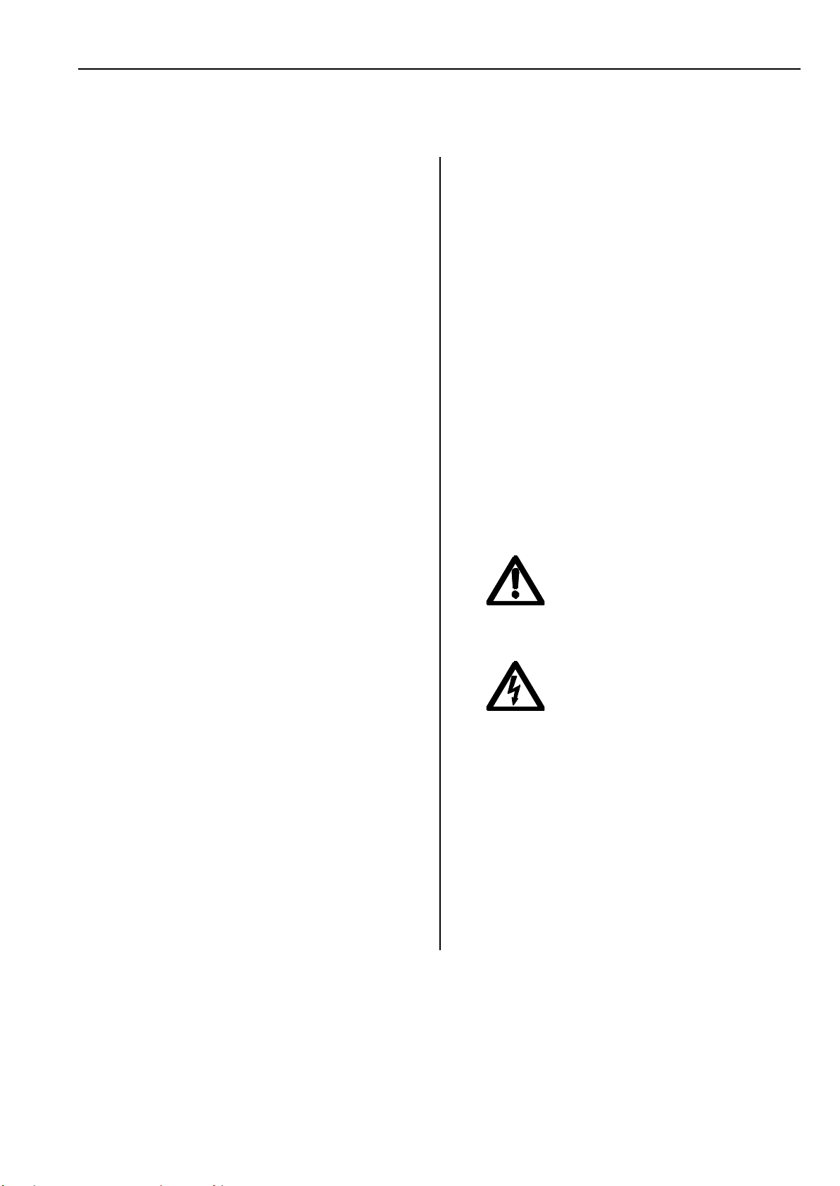
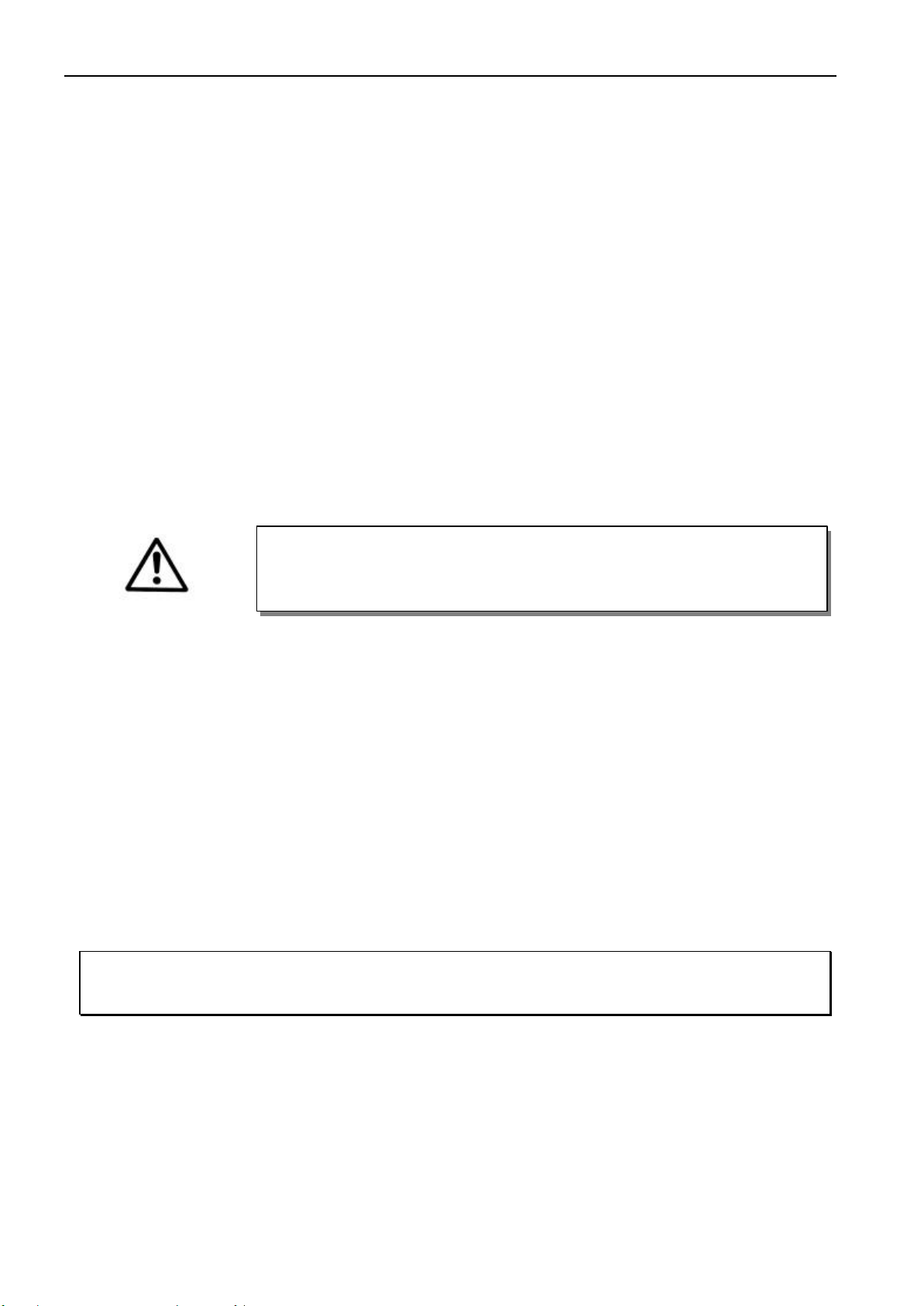
Warnings in the instruction manual which
point out particular risks of personal
injury or risk to the machine are marked
with this symbol wherever applicable.
This symbol is a warning on the control
and in the instruction manual. It indicates
hazardousvoltage.
CAUTION – In the case of failure this
area can be current-carrying even after
having turned the power off (non
dischargedcapacitors).
§The drive is not an independently operating unit, but is
designed to be incorporated into the machinery. It must not
be put into service until the machinery into which it is to be
incorporated has been declared in conformity with the
provisions of the EC Directive.
Save these instructions for future reference.

EFKA AB286A5400
6
2Range of Applications
The drive is suitable for industrial sewing machines and sewing automats of various manufacturers.
2.1 Use in Accordance with Regulations
The drive is not an independently operating machine, but is designed to be incorporated into other machinery. It must not
be put into service until the machinery into which it is to be incorporated has been declared in conformity with the
provisions of the EC Directive (Appendix II, paragraph B of the Directive 89/392/EEC and supplement 91/368/EEC).
The drive has been developed and manufactured in accordance with the relevant EC standards:
EN 60204-3-1:1990 Electrical equipment of industrial machines:
Particular requirements for industrial sewing machines, sewing units and sewing systems.
Operate the drive only:
§on thread processing machines
§in dry areas
3Complete Drive Unit Consisting of
1Direct current motor DC1500
1Electronic control AB286A5400
- Power pack N202
1Set of standard accessories B156
consisting of: Set of hardware
Documentation
1Set of accessories Z56
consisting of Potential equalization
cord
Note
If there is no metallical contact between drive (motor) and machine head, the potential equalization cord supplied
with the unit is to be wired from the machine head to the terminal provided on the control box!
3.1 Special Accessories
External actuator type EB301A with approx. 250 mm connecting cable - part no. 4170023
and 9-pin SubminD plug
Extension cable for motor connection, approx. 400 mm long - part no. 1111858
Extension cable for motor connection, approx. 1500 mm long - part no. 1111857
Sewing light transformer - please indicate line
voltage and sewing light
voltage (6.3V or 12V)
CAUTION
When selecting the installation site and the layout of the connecting cable, the Safety
Instructions in Section 1 must be followed with no exceptions.
Particular attention should be paid to maintaining the proper distance from moving

EFKA AB286A54007
4Starting Service
Before putting the control into operation, the following must be ensured, checked and/or adjusted:
§The correct installation of the drive, the position transmitter and accompanying devices, if necessary
§The correct adjustment of the direction of rotation of the motor
5Socket Connectors
The drive receives the commands necessary for its operation from a master computer. A socket with an RS485 interface
and further signal lines is provided for that. Moreover, the control has sockets for the connection of the motor, position
transmitter and external actuator.
B2 Socket for position transmitter in the motor
B18 Socket for 180° sensor
B41 Socket for motor power supply
B80 Socket for actuator
B485 Socket for RS485 interface and further signal lines
S1 Jumper for terminating resistor (see chapter
“Activate/Deactivate Terminating Resistor“)
Factory setting: Jumper S1 closed!
RS485
KL2342a
B485
S1
B18
180
B2
B41
B2
B18
M
B41
M
B80
EB...
B80

EFKA AB286A5400
8
6Connection Diagram
See chapter 15 for examples of connections!
Symbols: à= Output ß= Input ßà= bidirectional
Note
The connecting cable between computer and AB286A control must be shielded!
Note
All inputs and outputs of the AB286A control (socket B485) are potential-free!
1) RESET 1 in connection with external nominal voltage =24V, no-load voltage max. =36V
2) Output +5V, max. 15mA
3) TRI-STATE line (BUS-capable)
4) Differential driver outputs
5) Voltage +5V, Imax = 200mA

EFKA AB286A54009
POS1 Counting signal position 1
POS2+ / POS2- Differential outputs position 2
STOP Input for stop of the drive
SYN Synchronization window (180° track)
U/D Direction of rotation of the position transmitter
(counterclockwise = low / clockwise = high)
U/D+ / U/D- Differential outputs of the direction of rotation of the position transmitter
RESET 1 Reset 1 (low active with U = < 11V)
RESET 2 Reset 2 (low active with U = < 1.5V)
IRQ 1 Interrupt 1 (low active)
IRQ 2 Interrupt 2 (low active)
G1 512 impulses / rotation
G1+ / G1- Differential outputs 512 impulses / rotation
BAUD 1 Input 1 to set baud rates (low active)
BAUD 2 Input 2 to set baud rates (low active)
FEHLER Error output
EB... Actuator
2) Voltage +5V, Imax = 200mA

EFKA AB286A5400
10
180° SEN External signal
TxD/RxD No function (Do not connect anything to this socket!)
For external devices there is a supply voltage of +5Von socket B18/4. After opening the cover, this voltage can be changed
to +15V by moving a multipole connector J4 to a different position on the printed circuit board.
+15V =Connect righthand pins 3 and 4 with jumper
+5V =Connect lefthand pins 1 and 2 with jumper (factory setting)
2) Nominal voltage +5V, 100mA (can be changed to +15V, 100mA)
ATTENTION!
Before opening the cover, turn power off and remove mains plug from outlet!
B80
B2
B18
J4 1 3
2 4
+5V
J4
31
42
KL2351
+15V
J4

EFKA AB286A540011
7Interface Definition
Hinweis
In the BUS system with an EFKA interface motor other modules (e. g. I/O) must have an address less than $7F.
Note
A BUS termination resistor of 100 Ohm is provided in the control. Therefore, the control must be the last module to
be connected to the RS485 BUS. If several controls are connected, see chapter “Examples of Connections“.
7.1 Baud Rate Selection
Baud rate Jumper in plug B3
125,000 Baud All pins open
41,667 Baud Connect pin 16 to pin 15 (0V)
31,250 Baud Connect pin 17 to pin 15 (0V)
9,600 Baud Connect pins 16 and 17 to pin 15 (0V)
7.2 Protocol
§Data transfer according to ISO 1745.
§Only the commandsdata link establishment and RTS are valid.
§The control is selected withaddress $F0 (preset value). If several controls are connected further addresses up to $FF
are valid.
§Data transfer in ASCII (see also chapter ASCII Data Transfer).
§One word = 10 bit (1 start bit, 8 data bits, 1 stop bit, no parity bit).
7.3 Transmit Timeout before “NAK“
After detecting an error the “NAK“ acknowledgment will only be sent after a “timeout”. See the following table for the
length of the “timeout” depending on the baud rate.
125,000 Baud 2ms Timeout
41,667 Baud 3ms Timeout
31,250 Baud 4ms Timeout
9,600 Baud 10 ms Timeout
7.4 Byte to Byte Timeout
If, in a telegram, a “timeout” is exceeded from one word to the next, “NAK” will be sent. Simultaneously, bit 6 is set in the
communication register (parameter 00). See the following table for the length of the “timeout” depending on the baud rate.
125,000 Baud 6ms Timeout
41,667 Baud 8ms Timeout
31,250 Baud 10 ms Timeout
9,600 Baud 22 ms Timeout

EFKA AB286A5400
12
7.5 Communication Monitoring (System Values D, Group E)
A “timeout” for communication monitoring can be set by means of parameter E3. This “timeout” can be set at 10-
millisecond steps within a range of 0 and 255 (max. 2.5 seconds). If, in this parameter, a value not equal to zero is inputted,
there must always be an RTS to or a data link establishment with the slave within the allowed time. If the “timeout” is
exceeded, the drive stops in position 2 and sets bit 6 in the communication register (parameter 00). The “timeout” starts
with the next telegram after the data link establishment for parameter E3. Monitoring can be deactivated by inputting the
value zero in parameter E3 (preset value). Please note that the new value becomes effective only with the next telegram.
7.6 Control Characters
SOH $01 start of header
ADR $F0 address (can be set)
STX $02 start of text
ETX $03 end of text
ACK $06 acknowledge
NAK $15 not acknowledge
ENQ $05 enquiry
BCC Check sum EXOR logic operation from ADR to ETX
7.7 Special Characters
= $3D equals / value assignment
, $2C Separator in list call
. $2E Separator
7.8 Data Link Establishment
Higher level control = Master, AB286A = Slave
Master transmits -SOH ADR STX Text ETX BCC
Slave transmits -ADR ACK If telegram o.k.
-ADR NAK In case of error
Parameters in the control are modified by the data link establishment. The Text contains the modification information.
The general form of a modification is: Parameter = Value.
Parameter number and corresponding range of values are described in chapter Parameters.
7.9 RTS
Master transmits -SOH ADR STX Text ENQ
Slave transmits -SOH ADR STX Text ETX BCC
-ADR NAK In case of error
The Master receives information on the control status by means of RTS. This information is transmitted in the form of
status bytes. RTS only transmits the parameter number. More information on status bytes is described in chapter
Parameters.
7.10 Text
The Text contains all default options for the modification of settings in the AB286A control or polling of operational
statuses. These setings and operational statuses are described in detail in chapter Parameters.

EFKA AB286A540013
7.11 Stop Input
0 = Run / 1 = Stop
The start of the drive can be suppressed or the running motor can be stopped immediately by the “stop“ signal. The drive
can only be restarted after a reset (hardware or software). The stop signal must be on for at least 10ms.
7.12 Error Output
0 = Ready for operation / 1 = Error
The “error“ signal is issued whenever one of the following items applies:
§Hardware error
§Software error
§External 180° signal missing
§Commutation transmitter cord or frequency converter disturbed
§Line voltage too low
§Blocking, motor overstrained
Error description parameter 01 bit 2: If the external synchronization window is found after the command “go to
reference point“, this bit will be set. The error signal is issued and the drive stops.
The error signal can be reset (hardware or software).
8Parameters
The parameters are divided into the following groups:
Group 0: Status and Control Registers
Contain information on the actual control status.
Group 1-4: Control Values
The control values correspond to the system values after power on. They can be modified online
during the functional sequence.
Group 5-7: System Values
The system values serve as basic settings which are rarely modified. These values can be programmed
once and are saved after power off.
Attention: The system values cannot be modified during sewing.
Group E: Operational Statuses
The actual operational statuses can be read out here, e. g. actual counter reading or actual speed.
Group F: Characteristics
Contain information on the control, e. g. software version and module address.
Group 0
Parameter 00 - Communication Byte
Bit 0 = 1 In response to an RTS a list of parameter settings is transmitted
(see chapter ASCII Data Transfer)
Bit 1 = 0 Reserved (must always be 0)
Bit 2 = 1 Overflow in data link establishment (parameter value above or below setting range)
Bit 3 = 1 Access not authorized
Bit 4 = 1 Noise error in communication
Bit 5 = x Reserved
Bit 6 = 1 Timeout error in communication
Bit 7 = 1 Block check error (BCC) in communication
Bits 0 and 1 can be overwritten and read. All others can only be read.

EFKA AB286A5400
14
Parameter 01 - Error Byte
Bit 0 = 1 Hardware error
Bit 1 = 1 Software error
Bit 2 = 1 External 180° signal missing
Bit 3 = 1 Commutation transmitter cordor frequency converter disturbed
Bit 4 = 1 Line voltage too low
Bit 5 = 1 Blocking, motor overstrained
Bit 6 = 1 Parameter does not exist
Bit 7 = 1 Transmission is temporarily interrupted
Parameter 02 - Status Byte 1
Bit 0 = 1 Motor at standstill
Bit 1 = 1 Speed has been reached
Bit 2 = 1 Position has been reached
Bit 3 = 1 Is in position 2
Bit 4 = 1 Is in position 1
Bit 5 = 1 Drive is ready (after RESET)
Bit 6 = 1 Reference point has been reached
Bit 7 = 1 Position transmitter synchronized
Parameter 03 - Status Byte 2
Bit 0 = 1 Position 1E has been reached (E = leading)
Bit 1 = 1 Position 1A has been reached (A = trailing)
Bit 2 = 1 Position 2E has been reached
Bit 3 = 1 Position 2A has been reached
Bit 4 = 1 Position 3E has been reached
Bit 5 = 1 Position 3A has been reached
Bit 6 = 1 180° window has been reached
Bit 7 = 1 Reserved
Parameter 04 - Control Byte 1
Bit 0 = 1 Triggers a software reset
Bit 1 = 1 Direction of rotation cw
Bit 3/2 = 00 Speed 1 (Parameter 10)
= 01 Speed 2 (Parameter 11)
= 10 Speed 30 (Parameter 63)
= 11 Speed 40 (Parameter 64)
Bit 6-4 = 000 Motor operation
= 001 Fast stop (unpositioned)
= 010 Stop in position 1
= 011 Stop in position 2
= 100 Stop in position 3
= 111 Release the pedal
Bit 7 = 1 Go to reference point
Parameter 05 - Control Byte 2
Bit 0 = 1 Single impulse of position 2
Bit 1 = 1 Double speed (Attention: speed has been increased in steps of 4 RPM. This does not
apply to the positioning speed)
Bit 2 = 1 Disable accurate positioning
Bit 3-4 = 00 Stop with pedal in position 0 (neutral) èunpositioned (preset)
= 01 Stop with pedal in position 0 (neutral) èposition 1
= 10 Stop with pedal in position 0 (neutral) èposition 2
= 11 Stop with pedal in position 0 (neutral) èposition 3
Bit 5 Limit speed to the value set in parameter 64 (speed 40)
Bit 6 Enable control byte 03 (bits 3-4 will be blocked)
Bit 7 Reserved

EFKA AB286A540015
Parameter 06 - Status Byte 3
Bit 0-1 = 00 Stop with pedal in position –1 èunpositioned (preset)
= 01 Stop with pedal in position –1 èposition 1
= 10 Stop with pedal in position –1 èposition 2
= 11 Stop with pedal in position –1 èposition 3
Bit 2-3 = 00 Stop with pedal in position –2 èunpositioned (preset)
= 01 Stop with pedal in position –2 èposition 1
= 10 Stop with pedal in position –2 èposition 2
= 11 Stop with pedal in position –2 èposition 3
Bit 4-5 = 00 Stop with pedal in position 0 (neutral) èunpositioned (preset)
= 01 Stop with pedal in position 0 (neutral) èposition 1
= 10 Stop with pedal in position 0 (neutral) èposition 2
= 11 Stop with pedal in position 0 (neutral) èposition 3
Bit 6-7 = 00 Stop with pedal in position +1èunpositioned (preset)
= 01 Stop with pedal in position +1èposition 1
= 10 Stop with pedal in position +1èposition 2
= 11 Stop with pedal in position +1èposition 3
Parameter 08 - Status Byte 3
Bit 0 = 1 Pedal contact A closed
Bit 1 = 1 Pedal contact B closed
Bit 2 = 1 Pedal contact C closed
Bit 3 = 1 Pedal contact D closed
Bit 4 = 1 Pedal in position –2
Bit 5 = 1 Pedal in position –1
Bit 6 = 1 Pedal in off-position
Bit 7 = 1 Pedal pressed forward
Parameter 0A - Status Byte 3
Bit 0 Reserved
Bit 1 = 1 Counting direction from motor to handwheel inverted
Bit 2-7 Reserved
Parameter 0F - Interrupt Control Byte
Bit 0 = 1 Receive interrupt line 1 (IRQ1)
Bit 1 = 1 Transmit interrupt line 1
Bit 2 = 1 Receive interrupt line 2 (IRQ2)
Bit 3 = 1 Transmit interrupt line 2
Bit 5/4 = 00 IRQ1 delay with counter 1 (parameter 4C)
= 01 IRQ1 delay with counter 1, then with timer 1 (parameter 4D)
= 10 IRQ1delay with timer 1, then with counter 1
= 11 IRQ1 delay with timer 1
Bit 7/6 = 00 IRQ2 delay with counter 2 (parameter 4E)
= 01 IRQ2 delay with counter 2, then with timer 2 (parameter 4F)
= 10 IRQ2 delay with timer 2, then with counter 2
= 11 IRQ2 delay with timer 2
The function of the interrupt control is described in chapter Interrupt Control!

EFKA AB286A5400
16
Group 1 Control Value A
Parameter 10 - Speed 01 Speed 1 in [2 RPM] (with control byte 2 bit 1 = 1, then [4 RPM] )
Parameter 11 - Speed 02 Speed 2 in [2 RPM] (with control byte 2 bit 1 = 1, then [4 RPM] )
Parameter 12 - Positioning speed Positioning speed at [2 RPM]
Parameter 17 - Braking power Braking power at standstill (value changeable from 0 to 30).
After RESET parameter 57 will be read as preset value.
Parameter 18 - Ramp 1 Accelerating ramp [1/min * ms]
Parameter 19 - Ramp 2 Slowing down to intermediate speed [1/min * ms]
Parameter 1A - Ramp 3 Slowing down for positioning [1/min * ms]
Parameter 1B - Ramp 4 Positioning intensity
Group 4 Control Value D
Parameter 4C - Stitch counter IRQ1 Stitch delay for transmitting or receiving interrupt line 1
Parameter 4D - Timer IRQ1 Time delay for transmitting or receiving interrupt line 1
Parameter 4E - Stitch counter IRQ2 Stitch delay for transmitting or receiving interrupt line 2
Parameter 4F - Timer IRQ2 Time delay for transmitting or receiving interrupt line 2
Group 5 System Value A
Parameter 50 - Position 1E Position 1 leading edge
Parameter 51 - Position 1A Position 1 trailing edge
Parameter 52 - Position 2E Position 2 leading edge
Parameter 53 - Position 2A Position 2 trailing edge
Parameter 54 - Position 3E Position 3 leading edge
Parameter 55 - Position 3A Position 3 trailing edge
Parameter 56 - Syn. signal 0 = The reference point is generated by the transmitter in the motor
1 = Falling edge of the ext. sensor with positive counting direction is
the reference point
2 = Increasing edge of the ext. sensors with positive counting
direction is the reference point
Parameter 57 - Braking power Preset value for braking power at standstill (preset value = 0; i. e.
braking at standstill is not effective)
Parameter 58 - Ramp 1 Accelerating ramp [1/min * ms]
Is transferred to ramp 1 in case of reset. (parameter 18)
Parameter 59 - Ramp 2 Slowing down to intermediate speed [1/min * ms]
Is transferred to ramp 2 in case of reset. (parameter 19)
Parameter 5A - Ramp 3 Slowing down for positioning [1/min * ms]
Is transferred to ramp 3 in case of reset. (parameter 1A)
Parameter 5C - Ramp 4 Positioning intensity
Is transferred to ramp 4 in case of reset. (parameter 1B)
Group 6 Control Value B
Parameter 60 - Direction of rotation Direction of rotation of the motor ccw = 0, cw = 1
Contents is transferred to the control byte in case of reset
Parameter 61 - Speed 10 Speed 10 in [2 RPM]
(with control byte 2 bit 1 = 1, then [4 RPM] )
Is transferred to speed 1 in case of reset. (parameter 10)
Parameter 62 - Speed 20 Speed 20 at [2 RPM]
(with control byte 2 bit 1 = 1, then [4 RPM] )
Is transferred to speed 2 in case of reset. (parameter 11)
Parameter 63 - Speed 30 Speed 30 at [2 RPM]
(with control byte 2 bit 1 = 1, then [4 RPM] )
Parameter 64 - Speed 40 Speed 40 at [2 RPM]
(with control byte 2 bit 1 = 1, then [4 RPM] )
Parameter 65 - Maximum speed The speed is internally limited to this value
Parameter 66 - Positioning speed Positioning speed at [2 RPM]
Is transferred to positioning speed in case of reset. (parameter 12)

EFKA AB286A540017
Group 7 System Values C
Parameter 70 - P-divisor Dividing factor P-controller for adapting the running behavior to the
machine
Parameter 71 - I-divisor Dividing factor I-controller for adapting the running bahavior to the
machine
Parameter 72 - Stop segment Number of increments before stop position
Group E System Values D
Parameter E0 - Actual counter The actual counter reading of the position transmitter can be read out.
reading After a reset synchronization is necessary. Use command “go to
reference point“. Without synchronization a false value will be issued.
Parameter E1 - Actual speed The actual speed can be read out. It is issued at 2/min. The value must
thus be multiplied by 2.
Parameter E2 - Run-out stop segmentNumber of increments after stop position.
Parameter E3 - Communication Timeout beween the transfers. If the preset time is exceeded, the drive
monitoring stops in position 2 and sets bit 6 in the communication byte
(0 = funktion disabled).
Group F Characteristics
Parameter F0 - Entry 1 2 bytes as for ex. serial number can be entered here
Parameter F1 - Entry 2 2 bytes as for ex. workplace number can be entered here
Parameter F2 - Operating hours 2-byte operating hours.
Parameter F3 - Entry 3 2 bytes as for ex. repair note can be entered here
Parameter FA - P.c.b. no. Main board number
Parameter FB - Control box no. Control box number
Parameter FC - Efka type Type number with state of development
Parameter FD - Efka date code ID code
Parameter FE - Software version Program number with modification index
Parameter FF - Address The address of the AB286A control is filed here (preset = F0)
8.1 Special Features
When setting the speeds (parameters 10, 11, 61, 62, 63 and 64), half the value must be transmitted, i.e. the value “2000”
[2 RPM] must be transmitted for a requested speed of 4000 [RPM].
8.2 Bit Descriptions
8.2.1 “RDY“ Bit 5 in Status Byte 1
The “ready bit“ will not be set in case of the following errors:
0 = Error, as described below / 1 = Ready for operation
§Hardware error
§Software error
§Position transmitter not connected or defective
§Commutation transmitter cord or frequency converter disturbed
§Line voltage too low
§Blocking, motor overstrained

EFKA AB286A5400
18
8.2.2 “NPE“ Bit 6 in Status Byte 1
This status bit will be set if the drive is within a window of +/- 8 increments around the reference point after the command
“go to reference point”. When leaving this range, the bit will be erased. The drive goes to the reference point in conjunction
with control byte 1 bit 7 and the positioning speed (parameter 12). In order to stop exactly at the reference point the
positioning speed should be as low as possible.
8.2.3 “P1E, P1A, P2E, P2A, P3E, P3A“ in Status Byte 2
Status bits “PxE“ with increasing edge and “PxA“ with falling edge will be set for the corresponding position. These bits
are preserved until the next change of status of the respective position. Furthermore, the bits can be used for triggering an
interrupt (synchronization with position...).
8.2.4 “PSYN“ Bit 7 in Status Byte 1
This status bit is set after the position transmitter has been synchronized. Then the value in parameter E0 as well as all other
status signals of the positions are valid.
8.2.5 “P2T“ Bit 0 in Control Byte 2
If this bit has been set, a single impulse (LOW – HIGH – LOW) is issued at the output of position 2. This command will
only be executed at standstill. The bit is reset after issuing this impulse or whenever the drive has not stopped.
8.2.6 “2N“ Bit 1 in Control Byte 2
If this bit is set, the speeds are doubled. The quadruple speed must now be transmitted. Internally, the speed is limited to
10000 RPM. The positioning speed will not be doubled.
Control Byte 2 bit 1 = 0 èdouble speed
Control Byte 2 bit 1 = 1 èquadruple speed
8.2.7 “ZSTP_“ Bit 2 in Control Byte 2
If this bit is set, accurate positioning is disabled. The drive stops out of the positioning speed (parameter 68).
8.2.8 “PNLIM“ Bit 5 in Control Byte 2
At this setting the speed is limited if the pedal speed is higher. The pedal speed has priority if it is lower than this limit.
8.3 Functional Descriptions
8.3.1 Stop Segment Angle for Positioning (System -values C, Group 7)
An angle with which the stop point can be moved backward depending upon the set stop position can be set by means of
parameter 72. The positions (1E, 1A, 2E, 2A, 3E, 3A) will not be changed.
The preset value for parameter 72 is 0. The maximum value is 50 increments (e. g. 50 * 1.4° = 71.1°) and can be changed
in single increments. Transmission is done at 2 bytes.

EFKA AB286A540019
8.3.2 Run-Out Angle for Positioning (System Values D, Group E)
An angle with which the stop point can be moved forward depending upon the set stop position can be set by means of
parameter E2. The positions (1E, 1A, 2E, 2A, 3E, 3A) will not be changed. The preset value for parameter E2 is 6. The
maximum value is 25 increments and can be changed in single increments (i. e. 25 * 1.4° = 35°). Transmission is done at 2
bytes.
8.3.3 Accurate Positioning
Accurate positioning is time-optimized and reproducible. Ensure that the value of ramp 3 (the preset value in parameter 1A
corresponds to the value in parameter 5A) is lower than the maximum braking ramp determined by the system (3 to 5
[1/min * ms] lower than the maximum value). In order to determine the maximum braking ramp, set the value of ramp 3 to
the maximum (255). The value for ramp 3 is the quotient of speed and braking time (in ms).
In the example, the ramp is the quotient of speed change / time.
4500 [1/min] / 150 [ms] = 30 [1/min * ms]
[1/min]n
4500
150
[ms]t
0274-B12

EFKA AB286A5400
20
8.4 Table of Parameters
Values – Ranges – Preset (all data in decimal and hexadecimal form = $xxx)
Group No. Description MINIMUM MAXIMUM PRESET STEP
HEX DEC HEX DEC HEX DEC
1 10 Speed 1, [2 RPM] $023 35 $DAC 3500 Speed 10 1
1 11 Drehzahl 2, [2 RPM] $023 35 $DAC 3500 Speed 20 1
1 12 Positioningspeed $23 35 $FA 250 Parameter 68 1
1 17 Braking power at standstill $00 0 $32 50 Parameter 57 1
1 18 Ramp 1 [1/min*ms] $01 1 $37 55 Parameter 58 1
1 19 Ramp 2 [1/min*ms] $01 1 $37 55 Parameter 59 1
11A Ramp 3 [1/min*ms] $01 1 $37 55 Parameter 5A 1
11B Ramp 4 [1/min*ms] $01 1 $37 55 Parameter 5C 1
44C Stitch counter IRQ1 $00 0 $FF 255 $00 0 1
44D Timer IRQ1 [5ms] $00 0 $FF 255 $00 0 1
44E Stitch counter IRQ2 $00 0 $FF 255 $00 0 1
44F Timer IRQ2 [5ms] $00 0 $FF 255 $00 0 1
5 50 Position 1E $00 0 $FF 255 $80 128 1
5 51 Position1A $00 0 $FF 255 $8A 138 1
5 52 Position 2E $00 0 $FF 255 $00 0 1
5 53 Position2A $00 0 $FF 255 $0A 10 1
5 54 Position 3E $00 0 $FF 255 $C0 12 1
5 55 Position3A $00 0 $FF 255 $CA 202 1
5 56 Synchronization signal $00 0 $FF 255 $00 0 1
5 57 Braking power ar standstill $00 0 $32 50 $00 0 1
5 58 Ramp 1 [1/min *ms] $01 1 $37 55 $1C 28 1
5 59 Ramp 2 [1/min *ms] $01 1 $37 55 $14 20 1
55A Ramp 3 [1/min *ms] $01 1 $37 55 $1C 28 1
55C Ramp 4 [1/min *ms] $01 1 $37 55 $0A 10 1
6 60 Direction of rotation $00 0 $01 1 $00 0 1
6 61 Speed 10 $023 35 $DAC 3500 $8CA 2250 1
6 62 Speed 20 $023 35 $DAC 3500 $190 400 1
6 63 Speed 30 $023 35 $DAC 3500 $2FE 766 1
6 64 Speed 40 $023 35 $DAC 3500 $4E2 1250 1
6 65 Maximumspeed $023 35 $DAC 3500 $BB8 3000 1
6 66 Positioningspeed $23 35 $FA 250 $5A 90 1
7 70 P-divisor $01 1 $14 20 $04 10 1
7 71 I-divisor $01 1 $28 40 $06 6 1
7 72 Stop segment $00 0 $32 50 $06 6 1
EE0 Read out actual position $00 0 $FF 255 --- -
EE1 Read out speed $0000 0$0FFF 4095 --- -
EE2 Run-out angle $00 0 $32 50 $06 6 1
EE3 Communication monitoring $00 0 $FF 255 $00 0 1
FF0 Entry 1 (serial no.) $0000 0$FFFF 65535 $0000 0 1
FF1 Entry 2 (workplace) $0000 0$FFFF 65535 $0000 0 1
FF2 Operating hours $0000 0$FFFF 65535 $0000 0 1
FF3 Entry 3 (repair note) $0000 0$FFFF 65535 $0000 0 1
FFA P.c.b. no. Text 12 Text 12 ------ -
FFB Control box no. Text 8 Text 8 ------ -
FFC Efka type Text 8 Text 8 ------ -
FFD Efka date code Text 8 Text 8 ------ -
FFE Software version Text 8 Text 8 ------ -
F FF Module address $F0 240 $FF 255 $F0 240 1
Group No. Description Bit 76543210
0 00 Communication byte BCC TIM --- NOI ZUG BER --- LST
0 01 Error byte X0F PNV BLCK NETZ --- --- SOFT HARD
0 02 Status byte 1 PSYN NPE RDY P01 P02 P0E DZE STP
0 03 Status byte 2 --- 180 P3A P3E P2A P2E P1A P1E
0 04 Control byte 1 NPA STP3 STP2 STP1 V2 V1 DRI RES
0 05 Control byte 2 --- --- PNLIM PDST2 PDST1 ZSTP_ 2N P2T
0 08 Status byte 3 PED+ PED0 PED-1 PED-2 PEDD PEDC PEDB PEDA
00A Status byte 3 --- --- --- --- --- --- CNTD ---
00F Interrupt control byte TIQ2 ZIQ2 TIQ1 ZIQ1 SIQ2 EIQ2 SIQ1 EIQ1
Other manuals for dc 1500
1
This manual suits for next models
1
Table of contents
Other Efka Control System manuals