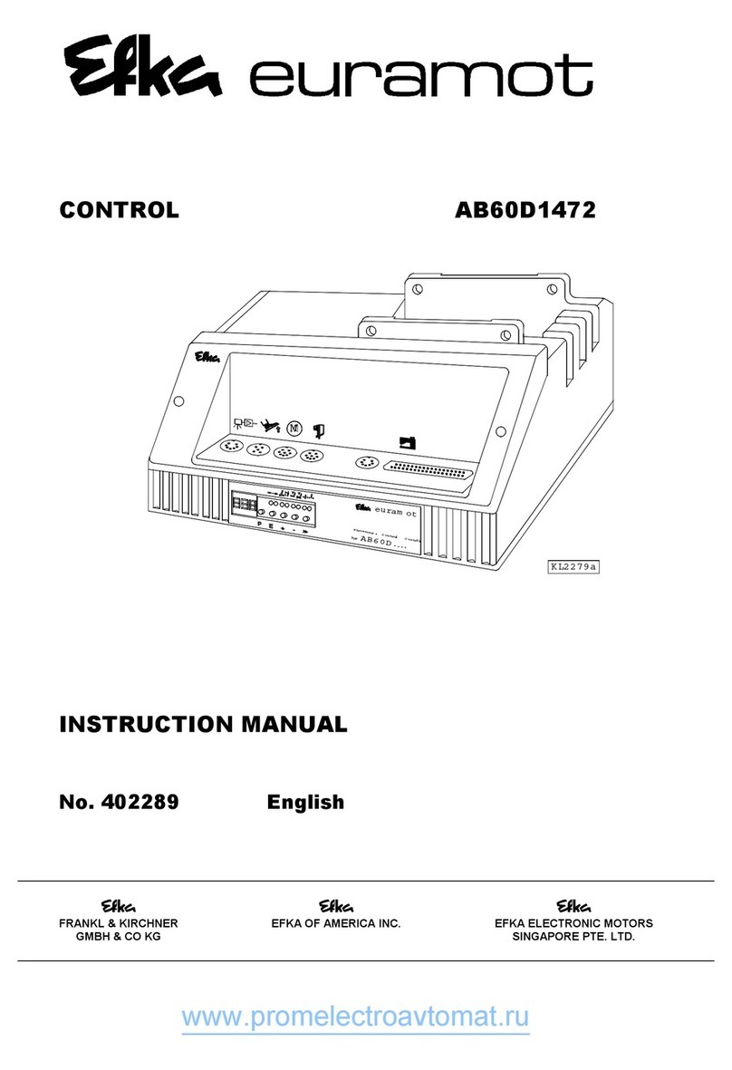
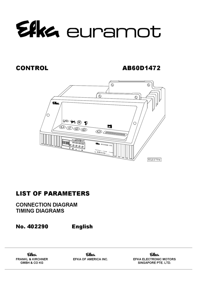
Efka vario dc DA82GA3312 User manual

CONTROL DA82GA3312
with control panel V810/V820
INSTRUCTION MANUAL
No. 402275 English
FRANKL & KIRCHNER EFKA OF AMERICA INC. EFKA ELECTRONIC MOTORS
GMBH & CO KG SINGAPORE PTE. LTD.

www.promelectroavtomat.ru

EFKA DA82GA3312
3
CONTENTS Page
1Range of Applications 6
1.1 Use in Accordance with Regulations 6
2Scope of Supply 6
2.1 Special Accessories 7
3Operation 8
3.1 Access Authorization upon Command Input 8
3.2 V810 Control Panel Operation 9
3.2.1 Code Number Input on the V810 Control Panel 9
3.2.2 Parameter Input at the Operator Level on the V810 Control Panel 9
3.2.3 Parameter Input at the Technician/Supplier Level on the V810 Control Panel 10
3.3 V820 Control Panel Operation 10
3.3.1 Code Number Input on the V820 Control Panel 10
3.3.2 Parameter Input at the Operator Level on the V820 Control Panel 11
3.3.3 Parameter Input at the Technician/Supplier Level on the V820 Control Panel 11
3.4 Program Identification 12
3.5 Direct Input of Maximum Speed Limitation (DED) with Control Panel 12
3.5.1 Setting on the V810 Control Panel 12
3.5.2 Setting on the V820 Control Panel 12
3.6 Keys for Background Information (HIT) with V820 13
3.6.1 Example of HIT 13
3.7 Programming of Seams 15
3.7.1 Programming Mode 16
3.7.2 Seam with Stitch Counting 16
3.7.3 Backward Seam with Stitch Counting 16
3.7.4 Stitch Counting and/or Light Barrier 16
3.7.5 Detailed Example 17
3.7.6 Maximum Number of Seams Exceeded 19
3.7.7 Execution (Pattern) Mode 19
3.7.8 Further Settings for TEACH IN 19
4Putting into Service 21
5Setting the Basic Functions 21
5.1 Direction of Motor Rotation 21
5.2 Selection of the Machine Series 21
5.2.1 Emergency Run Function If Machine Select Is Invalid 22
5.3 Positions 22
5.3.1 Setting the Reference Position 22
5.3.2 Setting the Reference Position on Control Panel V810 22
5.3.3 Setting the Reference Position on Control Panel V820 23
5.3.4 Setting the Positions on the V810 Control Panel 23
5.3.5 Setting the Positions on the V820 Control Panel 24
5.4 Positioning Speed 25
5.5 Maximum Speed Compatible with the Sewing Machine 25
5.6 Maximum Speed 25
5.7 Display of the Signal and Stop Positions 25
5.8 Braking Characteristics 26
5.9 Braking Power at Standstill 26
5.10 Starting Characteristics 26
5.11 Actual Speed Display 26

EFKA DA82GA3312 4
CONTENTS Page
6Functions and Settings 27
6.1 First Stitch after Power On 27
6.2 Softstart 27
6.2.1 Softstart Speed 27
6.2.2 Softstart Stitches 27
6.3 Sewing Foot Lifting 27
6.4 Sewing Foot Pressure Reduction 28
6.5 Start Backtack 29
6.5.1 Speed n3 at the Start of the Seam 29
6.5.2 Start Backtacking Stitch Count 29
6.5.3 Speed Release 30
6.5.4 Double Start Backtack 30
6.5.5 Single Start Backtack 30
6.6 End Backtack 30
6.6.1 Speed n4 at the Seam End 30
6.6.2 End Backtacking Stitch Count 31
6.6.3 Last Stitch Backward 31
6.6.4 Double End Backtack 31
6.6.5 Single End Backtack 31
6.6.6 Backtack Synchronization 31
6.7 Start and End Backtack with Switch-On and Switch-Off Delay 31
6.8 Start Ornamental Backtack 32
6.9 End Ornamental Backtack 32
6.10 Multiple Backtacking 33
6.11 Catch backtacking 33
6.12 Intermediate Backtack 33
6.13 Backtack Suppression/Recall 34
6.14 Holding Power of the Stitch Regulator Solenoid 34
6.15 Reverse Motor Rotation 35
6.16 Machine Run Blockage (Safety Switch) 35
6.16.1 Machine Start Blockage (Blockage 1 and 2) 36
6.16.2 Function “Machine Run Blockage”1 (Safety Function) Parameter 283 = 1 36
6.16.3 Function “Machine Run Blockage” 2 (Control Function) Parameter 283 = 2 36
6.17 Thread Monitor 37
6.17.1 Input Signals 37
6.17.2 Parameter 195 = 0 – No Thread Monitor Function 37
6.17.3 Parameter 195 = 1 – Model 270 / No Stop / Sewing Foot Down after Seam End 37
6.17.4 Parameter 195 = 2 – Model 767, N291 / With Stop / Sewing Foot Up after Seam End 37
6.17.5 Parameter 195 = 3 – Model 767, N291 / With Stop / Sewing Foot Down after Seam End 38
6.17.6 Parameter 195 = 4 – With Thread Monitor Stitch Counting 38
6.18 Needle Cooling 38
6.19 High Lift for Walking Foot 38
6.19.1 Manual High Lift for Walking Foot – Speed Limitation 39
6.19.2 Maximum High Lift for Walking Foot by Using a Key 39
6.19.3 High Lift for Walking Foot Operational Mode Not Stored (Pa. 138 = OFF, Pa. 184 = 0) 39
6.19.4 High Lift for Walking Foot Operational Mode Stored (Pa. 138 = ON) 39
6.19.5 High Lift for Walking Foot Operational Mode Not Stored with Minimum Number of
Stitches (Pa. 138 = OFF, Pa. 184 = >0) 39
6.20 Speed Limitation 39
6.20.1 Speed Limitation DB2000/DB3000 39
6.20.2 Analog Speed Limitation 40
6.20.3 Analog Speed Limitation Speedomat 40
6.20.4 Jumper S1 41
6.20.5 Setting the Speed Limitation Depending on High Lift with the V820 Control Panel 41
6.20.6 Setting the Speed Limitation Depending on High Lift with the V810 Control Panel 41

EFKA DA82GA3312
5
CONTENTS Page
6.21 Switch Stitch Length 42
6.22 Roller 42
6.23 Thread Clamp 43
6.24 Thread Trimming Operation 44
6.24.1 Thread Trimmer 44
6.24.2 Thread Wiper 44
6.24.3 Thread Tension Release 44
6.24.4 2nd Thread Tension Release (FSPL2) 45
6.24.5 Thread Tension Reduction 45
6.24.6 Coupling Thread Tension Release with the Sewing Foot 45
6.24.7 Coupling Thread Tension Reduction with High Lift for Walking Foot / Speedomat 45
6.25 Seam with Stitch Counting 46
6.25.1 Number of Stitches for a Seam with Stitch Counting 46
6.25.2 Stitch Counting Speed 46
6.26 Free Seam and Seam with Light Barrier 46
6.27 Light Barrier 47
6.27.1 Speed after Light Barrier Sensing 47
6.27.2 General Light Barrier Functions 47
6.27.3 Reflection Light Barrier LSM001A 48
6.27.4 Automatic Start Controlled by Light Barrier 48
6.27.5 Light Barrier Filter for Knitted Fabrics 48
6.28 Needle Up/Down / Single Stitch 48
6.29 F1/F2 Function Key Assignment on the V810/V820 Control Panels 49
6.30 Signal Output Position 2 50
6.31 Signal Output 512 Impulses per Rotation 50
6.32 Actuator 50
6.33 Acoustic Signal 51
6.34 Master Reset 51
7Input and Output Function Test 52
7.1 Function Test with the V810/V820 Control Panel 52
8Error Displays 53
9Operating Elements of the V810 Control Panel 54
10 Operating Elements of the V820 Control Panel 55

EFKA DA82GA3312 6
1 Range of Applications
The drive is suitable for lockstitch, machines:
Brand Series
DÜRKOPP ADLER N291, 069, 204, 205, 221, 266, 267, 268, 269,
366, 271, 381, 382, 467, 767, 768, 4180, 4280, 8967
1.1 Use in Accordance with Regulations
The drive is not an independently operating machine, but is designed to be incorporated into other machinery. It must not
be put into service until the machinery into which it is to be incorporated has been declared in conformity with the
provisions of the EC Directive (Appendix II, paragraph B of the Directive 89/392/EEC and supplement 91/368/EEC).
The drive has been developed and manufactured in accordance with the relevant EC standards:
EN 60204-3-1:1990 Electrical equipment of industrial machines:
Particular requirements for industrial sewing machines, sewing units and sewing systems.
Operate the drive only
on thread processing machines
in dry areas
2 Scope of Supply
1 Direct current motor DC1600
1 Electronic control vario dc DA82GA3312
- Power pack N153 (optional N155)
- Actuator EB301 (optional EB302, softer spring)
1 Control panel V810 (optional V820)
1 Position transmitter P6-1
1 Power switch NS108 (optional NS108D)
1 Set of standard accessories B131 1 Set of accessories Z57
consisting of: belt guard, complete consisting of: extension cable for EB3..
set of hardware
motor mounting foot
bracket 1 and 2, short
documentation
Note
If there is no metallical contact between drive (motor) and machine head, the potential equalization cord supplied
with the unit is to be wired from the machine head to the terminal provided on the control box!
CAUTION
When selecting the installation site and the layout of the connecting cable, the safety
instructions must be followed with no exceptions.
Particular attention should be paid to maintaining the proper distance from moving
parts!

EFKA DA82GA3312
7
2.1 Special Accessories
Control panel Variocontrol V810 - part no. 5970153
Control panel Variocontrol V820 - part no. 5970154
Reflection light barrier module LSM001A - part no. 6100028
EFKANET interface IF232-2 - part no. 7900068
Actuating solenoid type EM1.. (for e. g. sewing foot lifting, backtacking, etc.) - see specification
“solenoids” for
available models
Extension cable for commutation transmitter, approx. 1100 mm long, complete with - part no. 1112247
plug and socket connector
Extension cable for position transmitter, approx. 1100 mm long, complete with - part no. 1100409
plug and socket connector
Extension cable for motor connection, approx. 1500 mm long - part no. 1111857
Extension cable for external actuator, approx. 750 mm long, complete with - part no. 1111845
plug and socket connector
Extension cable for external actuator, approx. 1500 mm long, complete with - part no. 1111787
plug and socket connector
5-pin plug with locking screw for the connection of another external actuator - part no. 0501278
External actuator type EB302 (softer spring) with approx. 250 mm connecting - part no. 4170012
cable and 5-pin plug with locking screw
Foot control type FB301 with one pedal for standing operation, with approx. 300 mm - part no. 4170013
connecting cable and plug
Foot control type FB302 with three pedals for standing operation, with approx. 1400 mm - part no. 4170018
connecting cable and plug
Potential equalization cord 700 mm long, LIY 2.5 mm2, grey, with spades - part no. 1100313
on both sides
Pulley 40 mm Ø with special belt intake and slip-off protection (use SPZ belt) - part no. 1112223
Pulley 50 mm Ø with special belt intake and slip-off protection (use SPZ belt) - part no. 1112224
Knee switch type KN3 (pushbutton) with cord of approx. 950 mm length without plug - part no. 5870013
Sewing light transformer - please indicate line
voltage and sewing
light voltage
(6,3V or 12V)
Pitman rod for foot control - available versions
on inquiry
8-pin plug with locking screw MAS 8100S - part no. 0502865
8-pin plug with locking screw MAS 8100SN - part no. 0501279
15-contact SubminD male connector with half-shell housing - part no. 1113193
37-contact SubminD male connector with half-shell housing - part no. 1112900
Note
Select the pulley such that the motor runs at approx. 4000 RPM with max. stitch number.

EFKA DA82GA3312 8
3 Operation
3.1 Access Authorization upon Command Input
In order to prevent unintentional changes of preset functions the command input is distributed at various levels.
The following persons have access: - the supplier to the highest and all subordinate levels using a code number
- the technician to the next lower and all subordinate levels using a code
number
- the operator to the lowest level without using a code number
ACaCCallufruf
Call-up Supplier: Code number for the
control panel is
3112
Supplier Level
200 series of
parameter numbers
Technician: Code number for the
control panel is
1907
Technician Level
100 series of
parameter numbers
Operator Level

EFKA DA82GA3312
9
3.2 V810 Control Panel Operation
3.2.1 Code Number Input on the V810 Control Panel
Example: Technician level CODE number selection on the V810 control panel
TURN POWER OFF
+TURN POWER ON. First digit blinks !
Press the +or –key to select the first digit !
Press the >> key !
Second digit blinks !
Press the +or –key to select the second digit !
Press the >> key twice !
Fourth digit blinks !
Press the +or –key to select the fourth digit!
If the CODE number is correct, the first
PARAMETER number at the selected level
is displayed !
3.2.2 Parameter Input at the Operator Level on the V810 Control Panel
Example: CODE number has not been input !
TURN POWER ON !
First parameter at the operator level is
displayed.
Second parameter at the operator level is
displayed. The next or previous parameter
can be called by pressing the +/- keys.
Parameter value is displayed !
Change parameter value by pressing the
+/- keys.
Parameter value is entered.
Display advances to the next parameter.
Press the +key several times until the
desired parameter is displayed !
Parameter value is displayed !
Technician Level Code Number => 1907 and Supplier Level Code Number => 3112
P
C – 0 0 0 0
+
- C – 1 0 0 0
»C – 1 0 0 0
+
-C – 1 9 0 0
»» C – 1 9 0 0
+
- C – 1 9 0 7
E
F – 1 0 0
d A 8 2 G A
P
F – 0 0 0
+
F – 0 0 1
E
0 0 3
+
X X X
E
F – 0 0 2
+
F – 0 0 9
E
O F F

EFKA DA82GA3312 10
New parameter value is displayed !
Next parameter is displayed !
or
Exit programming !
These values are saved when you start sewing. They remain in effect even after turning the machine off!
3.2.3 Parameter Input at the Technician/Supplier Level on the V810 Control Panel
Example: After CODE number input at the technician level.
After CODE number input, the first
PARAMETER number is displayed!
Press the +key ! The next
parameter number is displayed !
Press key E!
The parameter value is displayed !
Change the parameter value !
Parameter value is entered.
Display advances to the next parameter.
or
Parameter value is entered.
The actual PARAMETER number is displayed!
or
Press key Ptwice !
Exit programming !
These values are saved when you start sewing. They remain in effect even after turning the machine off!
3.3 V820 Control Panel Operation
3.3.1 Code Number Input on the V820 Control Panel
Example: Technician level CODE number selection on the V820 control panel
TURN POWER OFF !
+TURN POWER ON !
Input CODE number !
+
O N
Note! The parameter number can also be selected directly, like the code number!
F – 1 0 0
+
F – 1 1 0
E
0 1 8 0
+
-0 X X X
E
F – 0 1 0
P
d A 8 2 G A
E
F – 1 1 1
P
F - 1 1 0
P
P
d A 8 2 G A
Technician Level Code Number => 1907 and Supplier Level Code Number => 3112
P
C–0000
1
9
C–1907
0
7

EFKA DA82GA3312
11
If CODE number is incorrect,
repeat input !
If CODE number is correct,
the first PARAMETER number at the
selected level is displayed.
3.3.2 Parameter Input at the Operator Level on the V820 Control Panel
Example: CODE number has not been input !
TURN POWER ON !
Display shows no reading !
Stitches for the start backtack forward at the
operator level are displayed. PARAMETER
number is not displayed.
Change the parameter value !
Parameter value is entered.
Display advances to the stitches for the
start backtack backward.
or
Exit programming !
3.3.3 Parameter Input at the Technician/Supplier Level on the V820 Control Panel
Example: After CODE number input at the technician level.
After CODE number input, the first
PARAMETER number is displayed.
The most significant digit of the
PARAMETER number blinks.
Input desired PARAMETER
number!
If PARAMETER number is incorrect,
repeat input!
If PARAMETER number is correct
Change the parameter value!
Parameter value is entered.
Display advances to the next parameter.
or
Parameter value is entered.
A new PARAMETER number can be
selected.
or
Press key Ptwice.
Exit programming!
These values are saved when you start sewing. They remain in effect even after turning the machine off!
E
C–0000 InFo F1
E
F–100
4000 dA82GA
E
Arv 003
E
Arr 003
P
4000 dA82GA
P
+
- Arv XXX
F-100
E
F-100
1 1 F-110
0
E
F–XXX InFo F1
E
F–110 n1 180
E
F-111 n2- 4000
P
F-XXX
+
- F-110 n1 XXX
P
P
4000 dA82GA

EFKA DA82GA3312 12
3.4 Program Identification
Function Parameter
Program number, modification index and identification number display 179
Display example parameter 179 on the V810 control panel:
Select parameter 179!
Press the Ekey e. g. 3312A is displayed (Program number with index)
Press the >> key e. g. 011105 is displayed (Identification number)
Press the Pkey twice dA82GA is displayed (Sewing process can be started)
Display example parameter 179 on the V820 control panel:
Select parameter 179!
Press the Ekey 312A 01110535 is displayed (Program number shortened by one
digit with index and identification
number)
Press the Pkey twice 4000 dA82GA is displayed (Sewing process can be started)
3.5 Direct Input of Maximum Speed Limitation (DED) with Control Panel
The maximum speed of the machine must be limited to the specific level according to the application. Do the setting at the
operator level using the +/- keys after each seam end. The actual value is shown on the display. The speed setting range is
between parameter 111 (upper limit) and parameter 121 (lower limit).
3.5.1 Setting on the V810 Control Panel
Type designation is displayed
Maximum speed is displayed
(reading remains on for max. 5 seconds)
Change the value;
e. g. press the –key 8 times !
After approx. 5 seconds the display shows
3.5.2 Setting on the V820 Control Panel
Actual display value at the operator level
Maximum speed and type designation are displayed
Change the maximum speed value;
e. g. press the –key 8 times !
This value is saved when you start sewing. It remains in effect even after turning the machine off!
d A 8 2 G A
+
4 0 0 0
+
-3 2 0 0
d A 8 2 G A
4000 dA82GA
+
- 3200 dA82GA
Note
Changing the setting of the maximum speed limitation also affects the start backtack, end backtack and stitch
counting speeds.

EFKA DA82GA3312
13
3.6 Keys for Background Information (HIT) with V820
(key assignment see figure on the last page)
For fast operator information, the values of functions enabled using key 1, 2, 3, 4 or 9 are displayed on the control panel for
approx. 3 seconds. During this time, the respective values can be varied directly by pressing the +or -key.
3.6.1 Example of HIT
Increase stitch-count seam section from 20 stitches to 25 stitches.
Stitch-count function (key 2) is off.
Display after power on
↓
↓↓
↓
Press key 2briefly ! Lefthand arrow
and stitch-count function are on
Press the +key !
Increase the number of stitches from 20 to 25 !
Display after approx. 3 seconds
Stitch-count function (key 2) is already On.
Display after power on
↓
↓↓
↓
Press key 2for at least 1 second!
Lefthand arrow goes off momentarily;
stitch-count function is on
Press the +key !
Increase the number of stitches from 20 to 25 !
Display after approx. 3 seconds
This value is saved when you start sewing. It remains in effect even after turning the machine off!
Function key F
Various parameters, even higher-level parameters, can be enabled or disabled by pressing the function key (key 9).
The following functions may be assigned to the function key:
1 Softstart ON/OFF
2 Ornamental backtack ON/OFF
3 High lift for walking foot operational mode stored = ON / operational mode not stored = OFF
4 Needle cooling ON/OFF
5 Reverse motor rotation ON/OFF
The key assignment can be changed as follows:
Display after power On
Press key P!
Note
The following functions are possible only with the V820 control panel!
4000 dA82GA
2 Stc 020
+
Stc 025
4000 dA82GA
2 Stc 020
+
Stc 025
4000 dA82GA
4000 dA82GA
P
4000 dA82GA

EFKA DA82GA3312 14
Press key E!
Press key Eseveral times until the
letter symbol –F– appears !
(ornamental backtack On/Off)
Press the –key!
(softstart On/Off)
Press key P!
The assignment is completed.
The number of softstart stitches can be changed as follows:
Example: change number of stitches from 1 to 3 (softstart function (key 9) is off).
Press key 9briefly !
The arrow above the key lights up
(softstart function is On)
Press the +key !
Number of stitches increases.
Display after 3 seconds
Example: change number of stitches from 1 to 3 (softstart function (key 9) is already on).
Press key 9for at least 1 sec. !
The arrow above the key goes off momentarily
(softstart function is On)
Press the +key !
Number of stitches increases.
Display after 3 seconds
This value is saved when you start sewing. It remains in effect even after turning the machine off!
E
c2 002
E
-F- 2
- -F- 1
P
4000 dA82GA
9 SSc 001
+
SSc 003
4000 dA82GA
9 SSc 001
+
SSc 003
4000 dA82GA

EFKA DA82GA3312
15
3.7 Programming of Seams
Um häufig vorkommende Nähabläufe komfortabel einstellen und abrufen bzw. verschiedene Nähte mit unterschiedlichen
Einstellungen aneinanderreihen zu können, ist die Naht-Programmierung möglich.
A maximum of 8 patterns with a total of 40 seams can be established.
Programming is possible only if a code number has not been input after powering on!
The functions “start backtack”, “end backtack”, “stitch counting”, “thread trimming” and “sewing foot lift” can
be assigned individually to each seam.
For all 8 patterns, different numbers of start and end backtacking stitches can be programmed.
The maximum number of stitches for the forward or backward section is limited to 15 stitches.
It is possible to “teach in” seams with stitch counting by executing the desired sections.
Example 1: Pattern 1 40 seams Example 3: Pattern 1 10 seams
Pattern 2-8 0 seams Pattern 2 15 seams
Example 2: Pattern 1 4 seams Pattern 3-8 0 seams
Pattern 2 5 seams
Pattern 3 6 seams
Pattern 4 25 seams
Pattern 5-8 0 seams
Examples 1 and 2 show that optimal utilization of the storage capacity is possible.
Functions of programming of seams:
21
1 2
11
5
5
3 4
43
7
7
6
6
13 1412 1615
0
10
8 9
98
R
F
BA
191817
EP
+-
1
KL2517
Function Arrow Function Arrow
1 Single start backtack On left 7 Basic position down left
Double start backtack On right Basic position up right
Start backtack Off --- 8 No function ---
2 Counted seam forward On left 9 Switching from one pattern or seam to the next according
to the setting of parameter 277
Counted seam backward On right 10 Memory for programming of seams On left
Counted seam Off --- Memory for programming of seams Off ---
3 Light barrier uncovered/covered On left 11 Program symbol
Light barrier covered/uncovered On right 12 Display of program number
Light barrier Off --- 13 Seam symbol
4 Single end backtack On left 14 Display of seam number
Double end backtack On right 15 Symbol of number of stitches of a seam
End backtack Off --- 16 Display of number of stitches
5 Thread trimmer On left 17 Light barrier symbol
Thread wiper On right 18 Display of light barrier compensating stitches
Thread trimmer and thread wiper On both 19 Programming mode On blinking
Thread trimmer and thread wiper Off --- Execution (pattern) mode On constant
6 Sewing foot in the seam On left A No function during programming
Sewing foot after seam end On right B No function during programming
Sewing foot in the seam and after seam end On both
Sewing foot Off ---

EFKA DA82GA3312 16
3.7.1 Programming Mode
Each seam pattern is programmed and stored separately.
Exit the teach-in mode after pattern input.
The values are saved when you start sewing.
Display configuration:
3Program number (1...8)
04 Seam number (0...40)
020 Stitches for a seam with stitch counting (0...254)
008 Stitches after light barrier sensing (0...254)
Programming:
After power On without code number input !
1 LC display is cleared
Display of a parameter
2 at the operator level
Lefthand arrow above key 0 blinks.
3 Entry into pattern and seam programming.
4 Changing the pattern number
The seam functions (e.g. sewing foot lift, start backtack, etc.) can be programmed using the keys on the control panel.
3.7.2 Seam with Stitch Counting
↓
↓↓
↓
Lefthand arrow above key 2 On;
stitch counting is On;
actual number of stitches is displayed.
3.7.3 Backward Seam with Stitch Counting
↓
↓↓
↓
Righthand arrow above key 2 On;
backward sewing is On; switch to
forward sewing by pressing the key again.
When sewing backward, all sewing operations including backtack are performed in reverse feeding direction. The functions
"light barrier seam" and "backward seam" block each other, i.e. the light barrier cannot be enabled if the backward seam
has been selected, or, backward sewing is not possible if the light barrier is enabled.
Change the number of stitches using the +/- keys,
or execute the seam section using the pedal !
3.7.4 Stitch Counting and/or Light Barrier
↓
↓↓
↓
Light barrier covered/uncovered On;
actual number of compensating stitches
is displayed.
3 04 020 008
P
E
aaa bbb
0 1 01 - - -
0 2 01 - - -
2 2 01 004
2 2 01 004
+
-
3 2 01 004 007

EFKA DA82GA3312
17
Changing the number of compensating stitches
If stitch counting and light barrier are to be On at the same time, the number of stitches for a seam with counting must be
programmed before the light barrier compensating stitches.
After programming the functions
Seam is entered;
the next seam is displayed.
The seam is entered by pressing key E or by heelback.
End of programming !
The first seam section to be executed
in the selected pattern is displayed.
After all seams have been programmed, each seam can be called again with the Ekey for checking.
Note
Several seam patterns cannot be programmed successively without interruption. Each pattern must be completed with
the P key; otherwise it gets lost.
Note
The patterns are permanently saved only after you have started sewing.
3.7.5 Detailed Example
A seam 1 with stitch counting and double start backtack, a seam 2 with stitch counting and a seam 3 with light barrier, end
backtack and thread trimmer are to be programmed under pattern number 4.
Display before programming
1 LC display is cleared
Display of a parameter
2 at the operator level
↓
↓↓
↓
Lefthand arrow above key 0 blinks.
3 Pattern 1, seam 1
↓
↓↓
↓
Lefthand arrow above key 0 blinks.
4 Pattern 2, seam 1
↓
↓↓
↓
Lefthand arrow above key 0 blinks.
5 Pattern 3, seam 1
↓
↓↓
↓
Lefthand arrow above key 0 blinks.
6 Pattern 4, seam 1
↓
↓↓
↓
Lefthand arrow above key 1 blinks.
7 Number of stitches for the start backtack
section backward is displayed. Vary the
number of stitches using the +/- key.
+
-
E
2 02 - - -
P
2 01 004 007
E
aaa bbb
0 1 01 - - -
0 2 01 - - -
XXXX
P
0 3 01 - - -
0 4 01 - - -
1 4 01 - - - 03

EFKA DA82GA3312 18
↓
↓↓
↓
Righthand arrow above key 1 blinks.
8Number of stitches for the start backtack
section forward is displayed. Vary the
number of stitches using the +/- key.
If a different key is pressed, start backtack section input is completed, and the righthand arrow above key 1 stops blinking.
The double start backtack is enabled.
↓
↓↓
↓
Righthand arrow above key 6 On.
9Sewing foot lift at the seam end is On.
↓
↓↓
↓
Lefthand arrow above key 2 On.
10 Stitch counting forward is On.
Change the number of stitches using the +/- keys,
11 or execute the seam section using the pedal.
Seam length is set at 17 stitches !
12 Pattern 4, seam 2
↓
↓↓
↓
Lefthand arrow above key 2 On.
13 Stitch counting forward is On.
Change the number of stitches using the +/- keys,
14 or execute the seam section using the pedal.
Seam length is set at 8 stitches !
15 Pattern 4, seam 3.
Free seam is selected.
↓
↓↓
↓
Lefthand arrow above key 3 On.
16 Light barrier covered/uncovered is On.
Change the number of stitches using the +/- keys;
17 5 compensating stitches are set.
↓
↓↓
↓
Lefthand arrow above key 4 blinks.
18 Number of stitches for the end backtack
section backward is displayed. Vary the
number of stitches using the +/- key.
If a different key is pressed, end backtack section input is completed, and the lefthand arrow above key 4 stops blinking.
The single end backtack is enabled.
↓
↓↓
↓↓
↓↓
↓
Both arrows above key 5 On.
19 Thread trimmer and thread wiper are On.
Pattern 4, seam 4.
20 Advance to the next seam acknowledges
the settings of the preceding seams.
Exit programming;
21 the first seam can be executed !
2 4 01 000
+
- 4 01 017
E
4 02 - - -
2 4 02 000
+
- 4 02 008
14 01 - - - 04
3 4 03 - - - 000
+
- 4 03 - - - 005
E
4 04 - - -
E
4 03 - - -
P
4 01 017
4
5 4 03 - - - 005
64 01 - - -
4 01 - - - 04

EFKA DA82GA3312
19
3.7.6 Maximum Number of Seams Exceeded
If by inputting a program the total number of 40 seams is exceeded, the teach-in mode cannot be completed by pressing the
Pkey. A new start of sewing is impaired. The display shows a warning (dEL). By pressing the Pkey again the pattern
displayed will be deleted. Exit the teach-in mode now if the total number of 40 seams is not exceeded. Otherwise there will
be a new warning.
Display:
X: Last input or selected pattern number (1...8)
YY: Number of programmed seams of the selected
pattern (0...40)
NN: Total number of input seams if more than 40
The user must now decide which pattern should be deleted !
Selection of the pattern to be deleted
X: Pattern number
YY: Number of seams of this pattern
NN: Total number of input seams if more than 40
Deletion of the pattern
X: Pattern number of the deleted pattern
YY: 00 = no more seam is programmed
NN: Total number of input seams if more than 40
Exit the teach-in mode if the number of seams equals or falls below 40, and the last input seam will be displayed.
3.7.7 Execution (Pattern) Mode
↓
↓↓
↓
Enable mode by pressing key 0
1 (arrow above key 0 lights up).
Seam number 01 is displayed.
Select pattern 1...8.
2
If you do not wish to start with seam 1,
3 press the Ekey several times until the
desired seam number is displayed !
Start the pattern by pressing the pedal !
Complete the execution (pattern) mode;
4 Disable mode by pressing key 0!
3.7.8 Further Settings for TEACH IN
Functions Parameter
Seam suppression if 0 stitches are set (Std) 275
Parameter 275 = 0 Seam suppression disabled: i. e. if the light barrier is Off and stitch counting is set at 0 stitches, a
free seam will be performed.
dEL X YY NN
0 dEL X YY NN
P
dEL X YY NN
0 X 01 ZZZ
+
- X 01 ZZZ
E
X 05 ZZZ
0

EFKA DA82GA3312 20
Parameter 275 = 1 Seam suppression enabled: i. e. if the light barrier is Off and stitch counting is set at 0 stitches, the
program switches to the next seam if the function is On. In case functions such as start of end
backtack, thread trimmer, are On, they will be performed before switching to the next seam.
Functions Parameter
Correction seam On/Off, seam or pattern interruption by thread trimmer (dkn) 276
Parameter 276 = 0 Correction seam disabled: The seam can be interrupted by pressing the pedal to pos. –2. The control
switches automatically to the next seam number.
Parameter 276 = 1 Correction seam enabled:
- The seam can be interrupted by pressing the pedal to pos. –2 and thread trimming, and a correction
seam (free seam) can be performed manually.
- The correction seam can be completed by pressing the pedal to pos. –2 or by light barrier if it is
On. Then the control switches automatically to the next seam number.
Parameter 276 = 2 Seam or pattern interruption by thread trimming:
- The seam can be interrupted by pressing the pedal to pos. –2 and thread trimming, even if the
thread trimmer is Off. Then the program switches back to the first seam of the selected pattern.
Functions Parameter
Selector: Switch from one seam or pattern to the next (nFS) 277
■Parameter 277 = 0 Switching from one seam to the next is active.
■Parameter 277 = 1 Switching from one pattern to the next is active.
This manual suits for next models
2
Table of contents
Other Efka Control System manuals