manuals.online logo
Brands
  1. Home
  2. •
  3. Brands
  4. •
  5. Crestron
  6. •
  7. Control System
  8. •
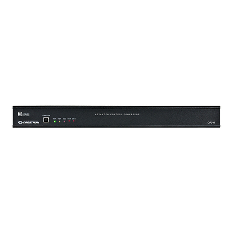
  9. Crestron 4K DigitalMedia 3-Series User manual

Crestron 4K DigitalMedia 3-Series User manual

DO GUIDE
CP3/CP3N
3-Series®Control System
The CP3 and CP3N are generally identical.
For simplicity within this guide, the term
“CP3” is used except where noted.
DO Install the Device
The CP3 can be mounted into a rack or
placed onto a at surface.
Mounting into a Rack
The CP3 occupies 1U of rack space. Using a
#1 or #2 Phillips screwdriver, attach the two
included rack ears to the device. Then, mount
the device into the rack using four mounting
screws (not included).
Placing onto a Flat Surface
When placing the device onto a at surface
or stacking it with other equipment, attach
the included feet near the corners on the
underside of the device.
DO Connect the Device
Hardware Hookup
Make the necessary connections as called out
in the diagram to the right. Connect power last.
When making connections to the CP3, note the
following:
• Use Crestron®power supplies for Crestron
equipment.
• The included cable(s) cannot be extended.
NOTE: Ensure the unit is properly grounded by
connecting the chassis ground lug to an earth
ground (building steel).
NOTE: The CP3 can be powered by the
4-position terminal block connector labeled NET
or with the (included) 24 Vdc power pack.
Connect the Control Subnet
(CP3N Only)
The CP3N has a dedicated Control Subnet that
is used for communication between the control
system and Crestron Ethernet devices. This
subnet allows for dedicated communication
between the control system and Crestron
Ethernet devices without interferences from
other network trafc on the LAN.
NOTE: Do not connect the CONTROL SUBNET port to the LAN. The
CONTROL SUBNET port must be connected only to Crestron Ethernet
devices.
For details on using the Control Subnet, refer to Doc. 7150 at
www.crestron.com/manuals.
DO Check the Box
QTY PRODUCT COLOR PART NUM.
2Connector, 3-Pin 2003575
1Connector, 4-Pin 2003576
1Connector, 5-Pin 2003577
4Connector, 8-Pin 2003580
1Connector, 9-Pin 2003581
1 Power Pack, 24 Vdc, 2.5 A, 100-240 Vac 2045873
1 Cable, USB 2.0, A - B, 6’ (1.83 m) 2014966
2Bracket, Rack Ear, 1U 2032122
4 Foot, 0.5" x 0.5" x 0.23", Adhesive Black 2002389
1 Power Cord, 5' 10" (1.78 m) 2042043
PORT RS-232 RS-4221RS-485
GGND GND GND2
TX TX (from CP3/CP3N) TX- (from CP3/CP3N) TX-/RX-
RX RX (to CP3/CP3N) RX+(to CP3/CP3N) Not Used
RTS RTS (from CP3/CP3N) TX+ (from CP3/CP3N) TX+/RX+
CTS CTS (to CP3/CP3N) RX- (to CP3/CP3N) Not Used
1. RS-422 transmit and receive are balanced signals requiring two lines plus a ground in
each direction. RXD+ and TXD+ should idle high (going low at start of data transmission).
RXD- and TXD- should idle low (going high at start of data transmission). If necessary,
RXD+/RXD- and TXD+/TXD- may be swapped to maintain correct signal levels.
2. A ground terminal connection is recommended but not required.
COM 1 Connections
RELAY OUTPUT (1-8):
To Contact Closure
Devices
IR-SERIAL (1-8):
To TTL/RS-232 Devices
COM 1:
To Serial
Controlled
Devices
COM 2 and 3:
To Serial
Controlled
Devices
MEMORY:
SD Compatible
Card Slot
LAN:
10/100/1000BASE-T
Ethernet to LAN
24V DC, 2.0 A:
From AC Power
Pack
Ground
NET:
To Cresnet Devices
I/O (1-8):
To Controllable Devices
CONTROL SUBNET (CP3N Only):
10/100/1000BASE-T
Ethernet to Control Subnet
USB:
To Storage Devices
DO GUIDE DOC. 7714C (2042569) 02.16
Specications subject to change without notice.
DO Congure the Control System
The CP3 can be congured using Crestron Toolbox™ software
and the built-in, web-based setup tool.
1. Use Crestron Toolbox to set the time zone. For details,
refer to the Crestron Toolbox help le.
2. Use Internet Explorer®browser to navigate to http://xxx.
xx.xx.xxx/setup, where xxx.xx.xx.xxx is the IP address of
the control system. The control system’s welcome screen
is displayed.
NOTE: The web-based setup tool is accessible only from
Internet Explorer.
NOTE: If a security warning is displayed, click Install to
continue.
3. Click Setup to display the CP3 setup menu. The CP3
setup menu displays the IP address, hostname, and MAC
address of the device. It also allows access to various
setup and programming screens.
4. From the CP3 setup menu, click the following options to
congure the control system:
• Ethernet Setup congures the CP3’s Ethernet
settings and displays DHCP, hostname, IP address,
subnet mask, default router, domain, and MAC
address settings. In the Ethernet setup menu, there
are additional options:
• Click Advanced Settings to specify DNS
servers, web server settings, and SSL settings.
• Click MyCrestron Dynamic DNS to congure
the myCrestron.com Dynamic DNS service.
DO Learn More
Visit the product page on the Crestron website
(www.crestron.com) for additional information. Use
a QR reader application on your mobile device to
scan the QR images.
Crestron Electronics
15 Volvo Drive, Rockleigh, NJ 07647
888.CRESTRON | www.crestron.com
As of the date of manufacture, the product has been tested and found to comply with specications for CE marking.
These products are Listed to applicable UL Standards and requirements by Underwriters Laboratories Inc.
Federal Communications Commission (FCC) Compliance Statement
This device complies with part 15 of the FCC Rules. Operation is subject to the following conditions:
(1) This device may not cause harmful interference and (2) this device must accept any interference received, including interference
that may cause undesired operation.
Caution: Changes or modications not expressly approved by the manufacturer responsible for compliance could void the user’s
authority to operate the equipment.
Note: This equipment has been tested and found to comply with the limits for a Class B digital device, pursuant to part 15 of the
FCC Rules. These limits are designed to provide reasonable protection against harmful interference in a residential installation.
This equipment generates, uses and can radiate radio frequency energy and, if not installed and used in accordance with the
instructions, may cause harmful interference to radio communications. However, there is no guarantee that interference will not
occur in a particular installation.
If this equipment does cause harmful interference to radio or television reception, which can be determined by turning the
equipment off and on, the user is encouraged to try to correct the interference by one or more of the following measures:
• Reorient or relocate the receiving antenna.
• Increase the separation between the equipment and receiver.
• Connect the equipment into an outlet on a circuit different from that to which the receiver is connected.
• Consult the dealer or an experienced radio/TV technician for help.
Industry Canada (IC) Compliance Statement
CAN ICES-3(B)/NMB-3(B)
Rack Mounting Safety Precautions
• Elevated Operating Ambient Temperature: If the unit is installed in a closed or multiunit rack assembly, the operating ambient
temperature of the rack environment may be greater than room ambient temperature. Therefore, consideration should be
given to installing the equipment in an environment compatible with the maximum ambient temperature (Tma) specied by the
manufacturer.
• Reduced Airow: Installation of the equipment in a rack should be such that the amount of airow required for safe operation
of the equipment is not compromised.
• Mechanical Loading: Mounting of the equipment in the rack should be such that a hazardous condition is not achieved due to
uneven mechanical loading.
• Circuit Overloading: Consideration should be given to the connection of the equipment to the supply circuit and the effect that
overloading of the circuits might have on overcurrent protection and supply wiring. Appropriate consideration of equipment
nameplate ratings should be used when addressing this concern.
• Reliable Earthing: Reliable earthing of rack-mounted equipment should be maintained. Particular attention should be given to
supply connections other than direct connections to the branch circuit (e.g., use of power strips).
Crestron product development software is licensed to Crestron dealers and Crestron Service Providers (CSPs) under a limited non-exclusive, non-transferable Software Development Tools
License Agreement. Crestron product operating system software is licensed to Crestron dealers, CSPs, and end-users under a separate End-User License Agreement. Both of these Agreements
can be found on the Crestron website at www.crestron.com/legal/software_license_agreement.
The specic patents that cover Crestron products are listed at patents.crestron.com. The product warranty can be found at www.crestron.com/warranty.
Certain Crestron products contain open source software. For specic information, please visit www.crestron.com/opensource.
Crestron, the Crestron logo, 3-Series, and Crestron Toolbox are either trademarks or registered trademarks of Crestron Electronics, Inc. in the United States and/or other countries. Internet
Explorer is either a trademark or registered trademark of Microsoft Corporation in the United States and/or other countries. UL and the UL logo are either trademarks or registered trademarks
of Underwriters Laboratories, Inc. in the United States and/or other countries. Other trademarks, registered trademarks, and trade names may be used in this document to refer to either the
entities claiming the marks and names or their products. Crestron disclaims any proprietary interest in the marks and names of others. Crestron is not responsible for errors in typography or
photography.
This document was written by the Technical Publications department at Crestron.
©2016 Crestron Electronics, Inc.
• Click Ethernet Diagnostics to test Ethernet
communications.
• Click Reboot to reboot the CP3.
• Application Setup selects programs to be loaded
on startup and controls which program(s) are
running.
• Input/Output Control congures the COM ports,
operates the relays, and monitors the Versiports.
• Diagnostics displays information about the
connected devices, hardware conguration, and
error logs.
• About displays rmware information.
Click to return to the previous screen.
CP3
CP3N
Other manuals for 4K DigitalMedia 3-Series

7

This manual suits for next models

2

Other Crestron Control System manuals

Crestron FlipTop FT2-202-ELEC Series User manual

Crestron

Crestron FlipTop FT2-202-ELEC Series User manual

Crestron PAC2 User manual

Crestron

Crestron PAC2 User manual

Crestron IRP2 User manual

Crestron

Crestron IRP2 User manual

Crestron AV2 User manual

Crestron

Crestron AV2 User manual

Crestron PAC2M User manual

Crestron

Crestron PAC2M User manual

Crestron CP2 User manual

Crestron

Crestron CP2 User manual

Crestron FlipTop FT2-202-ELEC-PTL User manual

Crestron

Crestron FlipTop FT2-202-ELEC-PTL User manual

Crestron FlipTop FT2 Series User manual

Crestron

Crestron FlipTop FT2 Series User manual

Crestron 4 Series User manual

Crestron

Crestron 4 Series User manual

Crestron FlipTop FT2-1200-ELEC-PTL User manual

Crestron

Crestron FlipTop FT2-1200-ELEC-PTL User manual

Crestron CNMSX-PRO User manual

Crestron

Crestron CNMSX-PRO User manual

Crestron CP4-R User manual

Crestron

Crestron CP4-R User manual

Crestron FlipTop FT2 Series User manual

Crestron

Crestron FlipTop FT2 Series User manual

Crestron 4 Series User manual

Crestron

Crestron 4 Series User manual

Crestron FlipTop FT2 Series User manual

Crestron

Crestron FlipTop FT2 Series User manual

Crestron 4 Series User manual

Crestron

Crestron 4 Series User manual

Crestron MC2W User manual

Crestron

Crestron MC2W User manual

Crestron 4 Series User manual

Crestron

Crestron 4 Series User manual

Crestron SmartPresenter SP-1 User manual

Crestron

Crestron SmartPresenter SP-1 User manual

Crestron 4 Series User manual

Crestron

Crestron 4 Series User manual

Crestron 3 Series User manual

Crestron

Crestron 3 Series User manual

Crestron CP4 User manual

Crestron

Crestron CP4 User manual

Crestron 3 Series User manual

Crestron

Crestron 3 Series User manual

Crestron FlipTop FT2 Series User manual

Crestron

Crestron FlipTop FT2 Series User manual

Popular Control System manuals by other brands

Dictator E8 Technical manual

Dictator

Dictator E8 Technical manual

Tekmar 062 Data brochure

Tekmar

Tekmar 062 Data brochure

Woodward ProAct I product manual

Woodward

Woodward ProAct I product manual

Felder Hammer HNC 47.82 Translation of the original operating instructions

Felder

Felder Hammer HNC 47.82 Translation of the original operating instructions

HUUM UKU manual

HUUM

HUUM UKU manual

Klafs 18043 operating instructions

Klafs

Klafs 18043 operating instructions

Helo OT 2 PS-1 product manual

Helo

Helo OT 2 PS-1 product manual

Huber Unistat T Series Operation manual

Huber

Huber Unistat T Series Operation manual

DoorKing 80 Series Installation & owner's manual

DoorKing

DoorKing 80 Series Installation & owner's manual

GE Multilin MM200 Communications guide

GE Multilin

GE Multilin MM200 Communications guide

Waterway NEO 2100 instruction manual

Waterway

Waterway NEO 2100 instruction manual

auto maskin DCU 305 R2 Communications manual

auto maskin

auto maskin DCU 305 R2 Communications manual

Baldor BC140 Installation and operation

Baldor

Baldor BC140 Installation and operation

CapstanAG PinPoint II Quick Reference Information

CapstanAG

CapstanAG PinPoint II Quick Reference Information

FCS Sentinel 2 user guide

FCS

FCS Sentinel 2 user guide

EVOKO NASO instruction manual

EVOKO

EVOKO NASO instruction manual

Actility Click&Go Quick starter guide

Actility

Actility Click&Go Quick starter guide

Tekmar Zone Control 369 Data brochure

Tekmar

Tekmar Zone Control 369 Data brochure

manuals.online logo
manuals.online logoBrands
  • About & Mission
  • Contact us
  • Privacy Policy
  • Terms and Conditions

Copyright 2025 Manuals.Online. All Rights Reserved.