EG4 MPPT100-48HV User manual

USER MANUAL
MPPT100-48HV
MPPT CHARGER
100A 48VDC
Version 1.0.0 - Information subject to change without notice.

ABOUT THIS MANUAL
Purpose
This manual describes the assembly, installation, operation, and troubleshooting for this unit. Please
read this manual carefully before installation and operation.
Scope
This manual provides safety and installation guidelines as well as information on tools and wiring.
SAFETY INSTRUCTIONS
WARNING: This chapter contains important safety and operating instructions.
Read and keep this manual for future reference.
1. Before using the unit, read all instructions and cautionary markings on the unit, the batteries and all
appropriate sections of this manual.
2. CAUTION
- To reduce the risk of injury, charge only deep-cycle, lead acid, or Li-Ion type
rechargeable batteries. Other types of batteries may burst, causing personal injury and damage.
3. Do not disassemble the unit. When service or repair is required, take it to a qualified service center.
Incorrect re-assembly may result in a risk of electric shock or fire.
4. To reduce the risk of electric shock, disconnect all wirings before attempting any maintenance or
cleaning. Turning off the unit will not reduce this risk.
5. CAUTION - Only qualified persons should install this device.
6. NEVER charge a frozen battery.
7. For optimum operation of this MPPT charger, please follow the required specs to select the
appropriate cable size.
8. Be very cautious when working with metal tools on or around batteries. A potential risk exists for a
dropped tool to spark or short circuit batteries or other electrical parts causing a fire.
9. Strictly follow installation procedures when connecting DC terminals. Please refer to the installation
section of this manual for details.
10. Breaker is required as over-current protection for the battery supply.
11. GROUNDING INSTRUCTIONS - This charger should be connected to a permanent grounded wiring
system. Be sure to comply with local requirements and regulations when installing this charger.
12. NEVER short DC inputs.
13. Warning!! Only qualified professionals are permitted to service this device. If errors persist
after following the troubleshooting table, please contact the tech department of the distributor where
you purchased your product.
1
DISCLAIMER
EG4 reserves the right to make changes to the material herein at any time without notice. You may refer
to the EG4 website at www.eg4electronics.com for the most updated version of our manual.
2
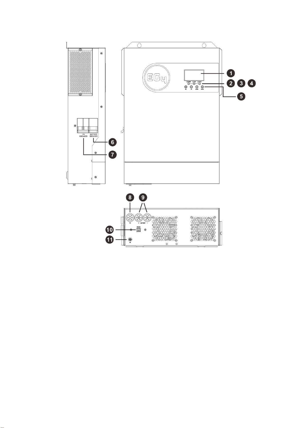
PRODUCT OVERVIEW
1.
LCD screen
2.
Power indicator
3.
Charging indicator
4.
Fault indicator
5.
Function buttons
6.
Battery breaker
7.
PV breaker
8.
PV wiring hole
9.
Battery wiring hole
10.
RS485 BMS communication port
11.
Grounding

3
INSTALLATION
Unpacking and Inspection
Before installation, please inspect the unit. Be sure that nothing inside the package is damaged. You
should have received the following items inside of the package:
1. The unit × 1
2. User manual × 1
3. RS485 BMS communication cable × 1
Preparation
Before installation, please take off bottom cover by removing the two screws.
Mounting the Unit
Consider the following points before selecting where to install:
1. Do not mount the charger on flammable construction
materials.
2. It is recommended to mount the unit on a solid surface,
preferably a wall.
3. Install this charger at eye level to allow the LCD screen
to be read at all times.
4. The ambient temperature should be between 32°F to
131°F (0°C to 55°C) to ensure optimal operation.
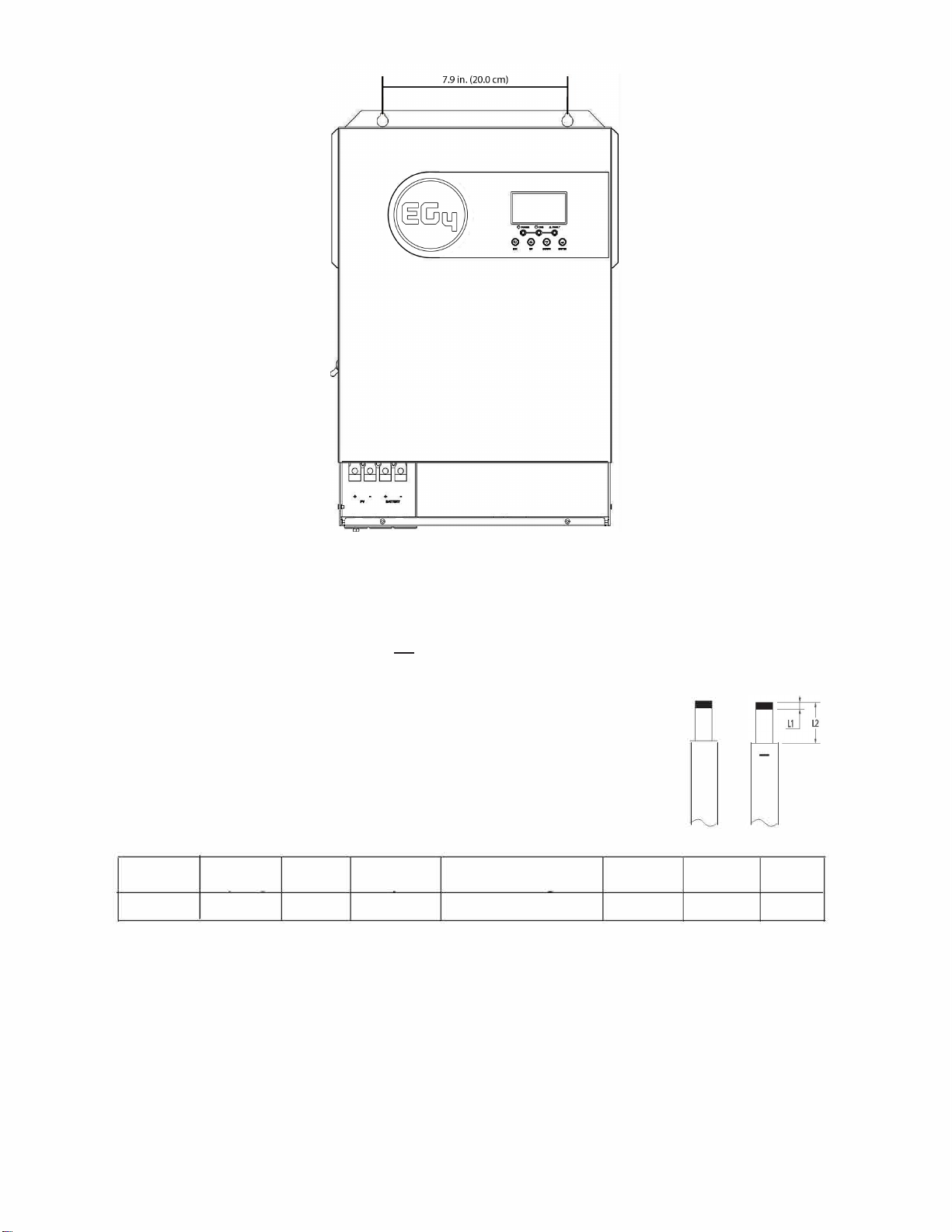
5. Please ensure sufficient spacing as shown in the diagram
to the right to guarantee proper heat dissipation and to
have enough space for removing wires.
SUITABLE FOR MOUNTING ON CONCRETE OR
OTHER NON-COMBUSTIBLE SURFACE ONLY.
Bae an
d
PV
Connection
s:
NOTE: This MPPT charger has a built-in battery breaker on the side panel of the unit for added safety,
protection, and to assist with code compliance. (For local codes, check with your local AHJ.)
Ensure the battery breaker is in the off position before installing battery cables.
+
WARNING!
We recommend all wiring be performed under the guidance of a
licensed professional.
WARNING!
It is very important for system safety and efficient operation to use
the appropriate
cable size for battery connections. To reduce the risk of injury,
please use
the recommended
cable, stripping length (L2), and tinning length (L1)
in the table below.
Recommended battery cable, stripping length (L2), and tinning length (Ll):
L1
MPPT100-48
100A100AH 3AWG/2AWG 6'/l.8m up to 15'/4.6m 3/0.1"
18/0.7"
Please follow these steps to ensure proper battery connection:
1. Remove insulation sleeve 18 mm (0.7") for positive and negative cables based on recommended stripping
length.
2. Connect all the batteries to the system. Insert the battery cable into the battery connector of the charger
and make sure the bolts are tightened with a torque of 2-3 Nm.
3. Make sure the polarity at both the battery and the charger is correct. Verify that the battery cables are
torqued to the proper value of the battery terminals to avoid loose connections.
2~ 3 Nm
4
Mount the unit by attaching with two screws. It is recommended to use M4 or M5 screws.

OPERATION
Power ON/OFF
1. Make sure the unit has been properly installed and the batteries are connected securely.
2. Verify that the PV modules are connected securely and within safe MPPT voltage range.
3. Turn on the battery breaker on the unit and then turn on the battery breakers/switches.
4. Turn on the PV breaker. When the modules produce sufficient power, the unit will power on and operate
normally.
Note:
•Only when both batteries and PV modules are properly wired and producing sufficient power will the
unit power on and operate normally.
•When the PV power is lost,the unit will go into standby mode and power off after about 2 minutes.
Only when the PV power returns to MPPT voltage range will the unit
power on and work normally.
LED Indicator Messages
Power Green Solid On The unit is powered on
CHG Green Solid On Battery is fully charged
Flashing Battery is charging
Fault Red Solid On Fault has occurred in the charger
Flashing Warning condition has occurred in the charger
Function Keys
Function Key Description
ESC To exit setting mode
UP To go to previous selection
DOWN To go to next selection
ENTER To confirm the selection in setting mode or enter setting mode
NOTE: This MPPT charger has a built-in PV breaker on the side panel of the unit for added safety,
protection and to assist with code compliance. (For local codes, check with your local AHJ.)
Ensure the PV breaker is in the off position prior to installing PV wires.
WARNING
We recommend all wiring be performed under the guidance of a licensed professional.
PV Wire Installation:
1. Remove insulation sleeve 10 mm/0.4" for positive and negative conductors.
2. Check correct polarity of connection cable from PV modules and PV input connectors. Then, connect
positive pole (+) of connection cable to positive pole (+) of PV input connector. Connect negative
pole (-) of connection cable to negative pole (-) of PV input connector.
3. Ensure PV cables are tightened to the proper torque specifications in the chart below.
5
PV Module Selection:
When selecting PV modules, please be sure to take into account that the temperature-adjusted open
circuit voltage (VOC) of the PV modules should not exceed the max PV array open circuit voltage of the
charger.
Operation and Display Panel
The operation and display panel, shown in the chart below, is located on the front panel of the
MPPT charger. It includes three indicators, four function keys and a LCD screen, indicating the
operating status
and the input/output power information of the charger.
LED Indicator

6
LCD Setting
After pressing and holding the ENTER button for 3 seconds, the unit will enter the settings mode. Press the “UP”
or “DOWN” button to select the proper settings program. Finally, press the “ENTER” button to confirm the
selection or the ESC button to exit.
Setting Programs:
Program
Description
Selectable option
01
Bulk charging
voltage (C.V
voltage)
Default value is 56.0V and the setting range is 48V - 62.0V. Please
note that the setting value must be greater than or equal the value
of program 2.
02
Float charging
voltage
Default value is 56.0V.
Setting range is from 48.0V - the value of program 1.
03
Maximum charging
current
Default value is 80A.
Setting range is from 5A - 100A.
04
Modbus ID Setting Modbus ID Setting Range:001(default)-247
05
Backlight control
Backlight on (default)
Backlight off
06
Buzzer mode
Mode1
Buzzer mute
Mode2
The buzzer sounds when the input source
changes or there is a specific warning or
fault.
Mode3
The buzzer sounds when there is a
specific warning or fault.
Mode4 (default) The buzzer sounds when there is a fault.
07
Battery type
User-defined (default)
If “User-Defined” is selected, battery
charge voltage can be set up in program
01 and 02.
LI
EG4 battery protocol
Setup for lithium battery without communication
These settings are used for lithium battery applications without BMS communication. Please follow these
setting suggestions:
1. Before setting, please obtain the following battery BMS specifications:
a) Max charging voltage
b) Max charging current
2. Set battery type (Program 07) as user-defined.
3. Set C.V voltage (Program 01) as the max charging voltage of your battery.
4. Set float charging voltage (Program 02) as C.V voltage minus 0.5V.
5. Set the max charging current (Program 03), which must be less than the max charging current of the
BMS. (Please refer to the battery specifications for the recommended charging current.)
7
Pin
Setting for lithium battery with communication
Caution:
When the charger and inverter are communicating to the battery system simultaneously, the system may
be unstable. It is best to connect the BMS of the battery to the inverter and disconnect the MPPT charger
communication. Then let the charger work without communication in user-defined mode.
Lithium Battery Connection
If you are using an EG4 lithium battery for the MPPT charger, you can use the preconfigured lithium battery
protocol. The EG4 battery has RS485 connections to connect to the BMS port of the charger.
Please follow the steps below to implement lithium battery communication:
1. Locate your included RS485 BMS communication cable.
2. Connect the end of RS485 port of battery to BMS (RS485) communication port of charger.
3. Finish setting program 07 as LI.
4. If communication between the charger and battery is successful, the charger will work normally.
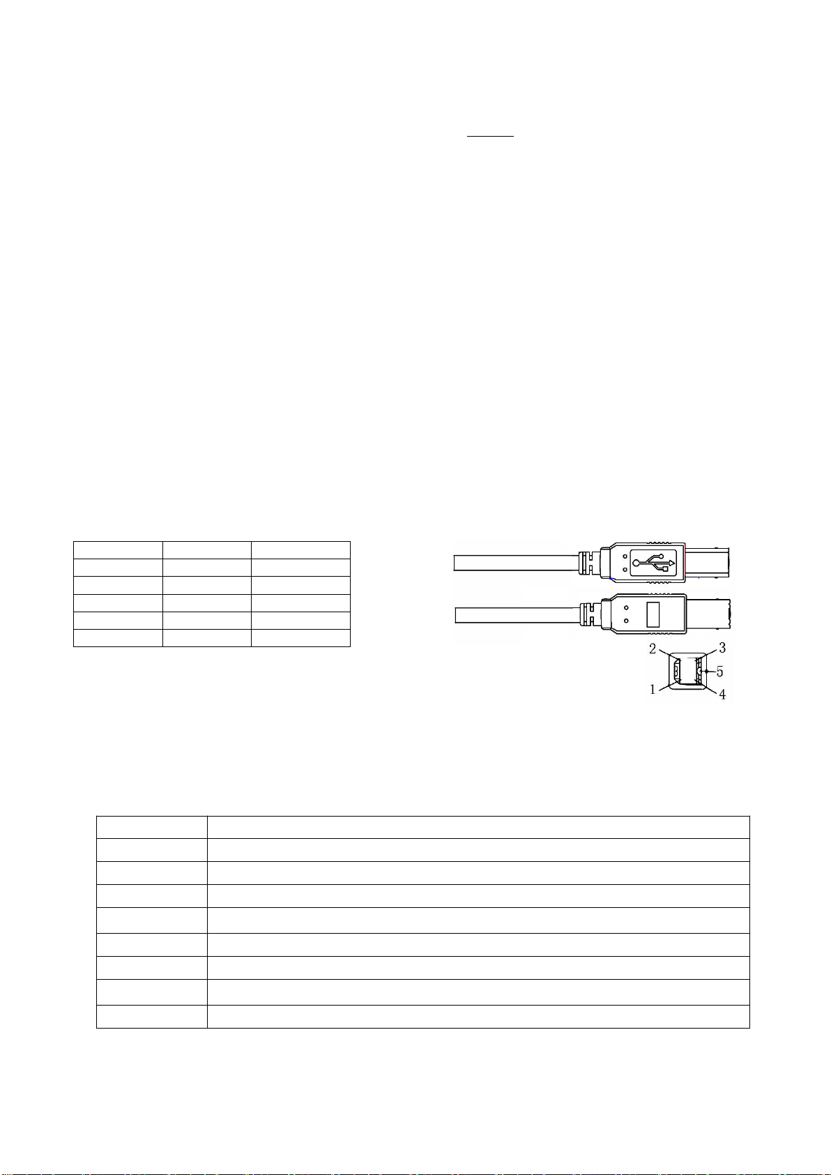
The charger RS485 port pin assignment is shown below:
number RS485 Port Wire color
PIN1 RS485-B Red
PIN2 RS485-A White
PIN3 GND Green
PIN4 GND Yellow
PIN5 NC NC
Fault Reference Codes
Fault Code Fault Event
01 Bus soft start failed
02 PV voltage is too high
03 Over temperature of DCDC module
05 PV current offset is too high
06 Bus voltage is too high
07 Battery voltage is too high
08 Battery current offset is too high
09 Lithium battery communication is abnormal
8
SPECIFICATIONS
MPPT Charging Mode
CHARGER MODEL 5KW
Max Charging Current 100Amp
Bulk
Charging
Voltage 56.4Vdc
Floating Charging Voltage 54Vdc
Overcharge Protection 63Vdc
Charging Algorithm 3-step
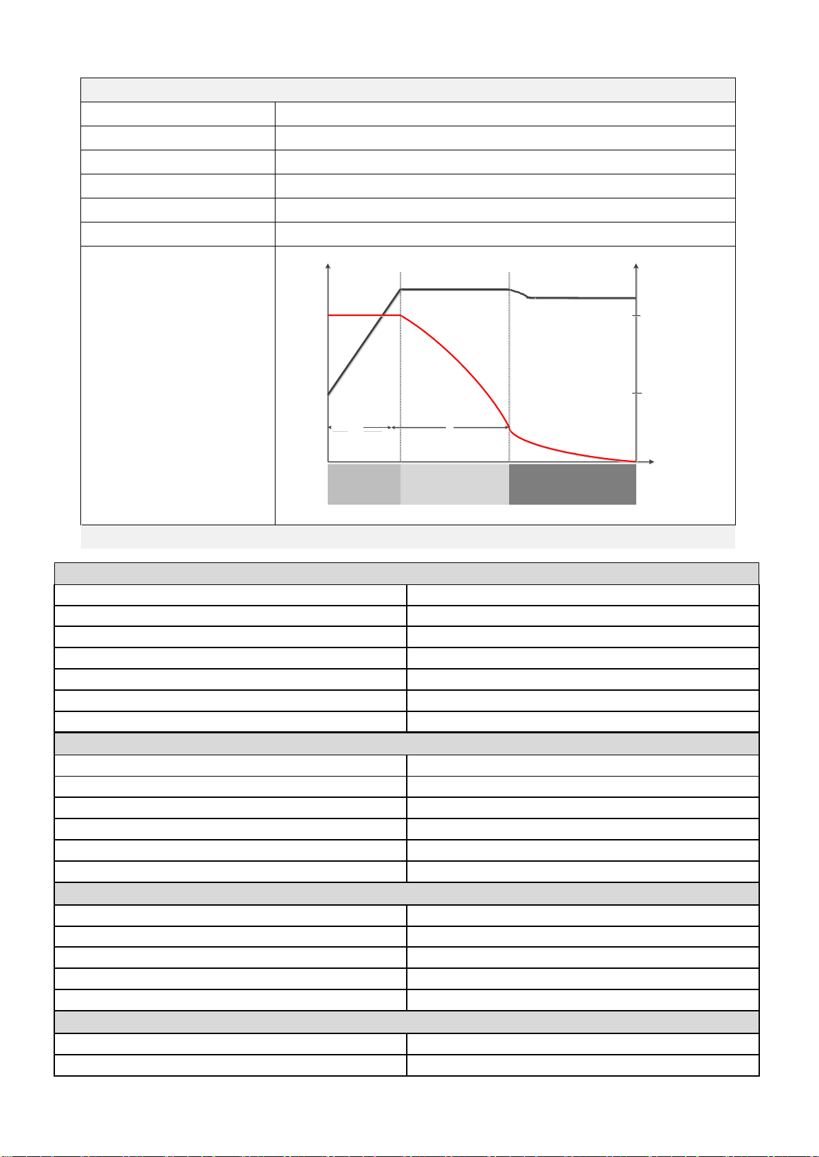
Charging Curve
Battery Voltage, per cell Charging Current, %
2.43Vdc (2.35Vdc)
Voltage
2.25Vdc
100%
50%
T0 T1
T1 = 10* T0, minimum 10mins, maximum 8hrs
Current
Time
Bulk Absorption Maintenance
(Constant Current) (Constant Voltage) (Floating)
Charger Specifications
Battery Voltage 48Vdc nominal
Charge Current 5-100A (default 80A)
Bulk Charging Voltage 48-62Vdc (default 56Vdc)
Float Charging Voltage 48Vdc to bulk charging voltage (default 56Vdc)
Overcharge Protection 63Vdc
Max Efficiency 94%
Self-Consumption <25W
Solar Specifications
Max PV Array Open Circuit Voltage 500Vdc
PV Array MPPT Operating Voltage Range 120-450Vdc
Number of Trackers 1
Max Solar Current Draw 18A
Max PV String Current 22A
Max Usable PV Array Power 5500W
Environmental Specifications
Operating Temperature Range 14°F to 131°F (-10°C to 55°C)
Storage Temperature 5°F to 140°F (-15°C to 60°C)
Humidity 5% to 95% relative humidity (non-condensing)
IP Rating IP21
Operating Altitude 0~4921 ft. (0~1500 m)
Physical Specifications
Dimensions H×W×D 17.2×11.6×4.7 in. (43.8×29.5×12.0 cm)
Net Weight 17.8 lbs. (8.1 kg)
Table of contents
Other EG4 Batteries Charger manuals


LG Standart manual")


