EG4 8KEXP-240 User manual

EG4 Electronics www.eg4electronics.com
USER MANUAL
EG4 8KEXP-240
HYBRID INVERTER/CHARGER
8000W 120/240 VAC
Version 1.0.0 - November 2022
1

Table of Contents
1. NOTES ON THIS MANUAL…………………………………………………………..2
1.1 SCOPE OF VALIDITY………………………………………………………………………………………………..2
1.2 TARGET GROUP ……………………………………………………………………………………………………..2
1.3 SYMBOLS USED………………………………………………………………………………………………………2
2. SAFETY...………………………………………………………………………………..3
2.1 IMPORTANT SAFETY INSTRUCTIONS………………………………………………………………………..3
2.2 EXPLANATION OF SYMBOL………………………………………………………………………………………7
3. INTRODUCTION...…………………………………………………………………....8
3.1 BASIC FEATURES…………………………………………………………………………………………………...8
3.2 SYSTEM DIAGRAM………………………………………………………………………………………………….8
3.3 WORK MODES………………………………………………………………………………………………………11
3.4 DIMENSION………………………………………………………………………………………………………….12
3.5 TERMINALS OF PV INVERTER…………………………………………………………………………………13
4. TECHNICAL PARAMETERS..……………………………………………………...14
4.1 INVERTER SPECIFICATION…………………………………………………………………………………….14
5. INSTALLATION………………………………………………………………………16
5.1 CHECK FOR PHYSICAL DAMAGE……………………………………………………………………………..16
5.2 PACKING LIST……………………………………………………………………………………………………….16
5.3 MOUNTING…………………………………………………………………………………………………………..17
6. ELECTRICAL CONNECTION……………………………………………………….20
6.1 PV CONNECTION…………………………………………………………………………………………………..20
6.2 GRID CONNECTION (GEN CONNECTION)...................................................................21
6.3 BACK-UP:LOAD1 AND LOAD2 CONNECTION…………………………………………………………….22
6.4 BATTERY CONNECTION…………………………………………………………………………………………24
6.5 METER CONNECTION…………………………………………………………………………………………….26
6.6 WIFI CONNECTION (OPTIONAL)...............................................................................27
6.7 GPRS CONNECTION (OPTIONAL)..............................................................................27
6.8 CT INSTALLATION INSTRUCTIONS………………………………………………………………………...27
7. LCD OPERATION…………………………………………………………………….29
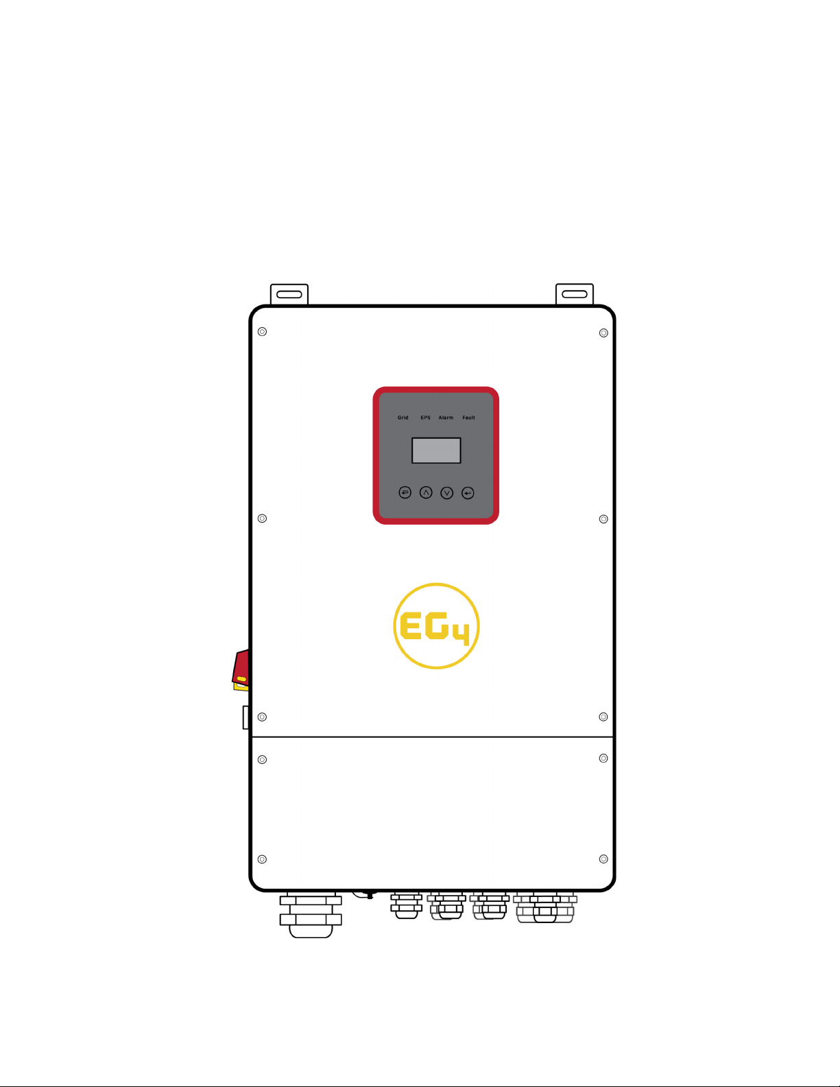
7.1 CONTROL PANEL…………………………………………………………………………………………………..29
7.2 INSTRUCTIONS FOR LED INDICATOR……………………………………………………………………..29
7.3 INSTRUCTIONS FOR THE USE OF THREE MODES…………………………………………………….30
8. LCD OPERATION…………………………………………………………………….32
8.1 LCD OPERATION……………………………………………………………………………………………………32
8.2 SETTING………………………………………………………………………………………………………………37
9. FAULT DIAGNOSIS AND SOLUTIONS..………………………………………..51
2

1 Notes on this Manual
1.1 Scope of Validity
This manual describes installation, commissioning, operation, and troubleshooting. Please read
the manual fully and carefully before installing and operating. This manual provides basic safety and
installation guidelines as well as information on tools and wiring. Keep this manual for future use.
1.2 Target Group
This manual is for qualified electricians and owner/builders with qualified electrician
oversight.
1.3 Symbols Used
The following types of safety instructions and general information appear in this document as
described below:
3

2 Safety
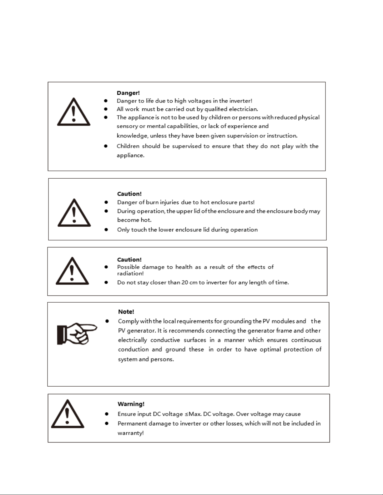
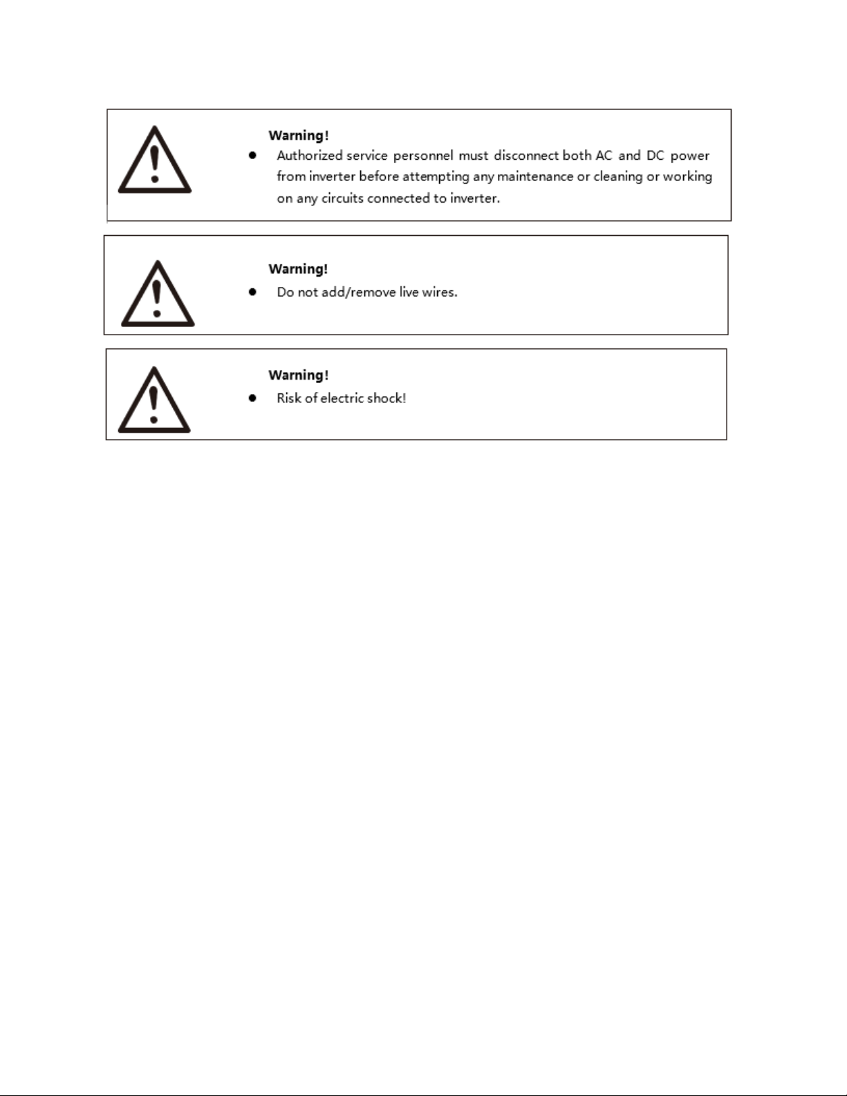
2.1 Important Safety Instructions
4

●Please keep this user manual for future use. Always follow the precautions, and safety
instructions in this document. EG4 will not be liable for any consequence caused by the violation
of the safety regulations, design, production, and usage standards.
●Only accessories included with the inverter shipment are recommended for use with the inverter.
Modification or unapproved components may result in a risk of fire, electric shock, or injury to
person.
●Make sure that existing wiring is in good condition and that wire is not undersized. Do not
disassemble any parts of the inverter which are not mentioned in the installation guide. It
contains no user-serviceable parts. See Warranty for instructions on obtaining service. Attempting
to service the inverter yourself may result in a risk of electric shock or fire and will void your
warranty.
●Keep away from flammable, explosive materials to avoid possible fires.
●The installation place should be away from humid or corrosive substances.
●Authorized service personnel must use insulated tools when installing or working with this
equipment.
●Never touch either the positive or negative pole of a PV connecting device. Never touch both of
them at the same time.
●The unit contains capacitors that remain charged to a potentially lethal voltage after the
utility, battery and PV supply has been disconnected.
●Hazardous voltage will present for up to 5 minutes after disconnection from the power supply.
●CAUTION-RISK of electric shock from energy stored in capacitor, never perform maintenance on
the inverter couplers, utility cables, battery cables, or PV cables while power is applied. After
switching off the PV, battery and utility; wait for 5 minutes to let the intermediate circuit
capacitors discharge before unplugging PV, battery, and utility couplers.
●When accessing the internal circuit of the inverter, it is very important to wait 5 minutes before
operating the power circuit or demounting the electrolyte capacitors inside the device. Do not
open the device beforehand since the capacitors require time sufficiently discharge!
●Please use surge protection devices (SPDs) for PV installation.
5

●Lightning will cause damage either from a direct strike or from surges due to a nearby strike.
●Induced surges are the most likely cause of lightning damage in majority or installations,
especially in rural areas where electricity is usually provided by long overhead lines. Surge may
be included on both the PV array conduction and the AC cables leading to the building.
●Specialists in lightning protection should be consulted during the end use application. Using
appropriate external lightning protection, the effect of a direct lightning strike into a building can
be mitigated in a controlled way.
●Installation of SPDs to protect the inverter against mechanical damage and excessive stress
include a surge arrester in case of a building with external lightning protection system (LPS)
when separation distance is kept.
●To protect the DC system, a surge suppression device (SPD type2) should be fitted at the inverter
end of the DC cabling and at the array located between the inverter and the PV generator. If the
voltage protection level (VP) of the surge arresters is greater than 1100V, an additional SPD type
3 is required for surge protection for electrical devices.
●To protect the AC system, surge suppression devices (SPD type2) should be fitted at the main
incoming point of AC supply (at the consumers cutout), located between the inverter and the
meter/distribution system.
●All DC cables should be installed to provide as short a run as possible, and positive and negative
cables of the string or main DC supply should be bundled together. This avoids the creation of
loops in the system.
●Spark gap devices are not suitable to be used in DC circuits once conducting, they won’t stop
conducting until the voltage across their terminals is typically more than 30 volts.
➢Anti-Islanding Effect
Islanding effect is a special phenomenon that grid-connected PV system still supply power to the nearby
grid when the voltage loss is happened in the power system. It is dangerous for maintenance personnel
and the public. This inverter provides Active Frequency Drift(AFD) to prevent islanding effect.
➢PE Connection and Leakage Current
The end-use application shall monitor the protective conductor by residual current operated protective
device (RCD) with rated fault current Ifn≤240mA. This automatically disconnects the device in case of a
fault. The device is intended to connect to a PV generator with a capacitance limit of approximately
700nf.
Incorrect grounding can cause physical injury, death or equipment malfunction.
6

➢Battery Safety Instructions
This inverter must use low voltage batteries. For the specific parameters such as battery type, nominal
voltage and nominal capacity etc., please refer to section 4.3.
Connecting batteries in parallel contains risk of potential electric shock and short-circuit current danger.
To avoid accidents, the following warnings should be observed during battery replacement:
1: Do not wear watches, rings or similar metallic items.
2: Use insulated tools.
3: Put on rubber shoes and gloves.
4: Do not place metallic tools and similar metallic parts on the batteries.
5: Switch offload connected to the batteries before dismantling battery connection terminals.
6: Only personnel with proper expertise can carry out the maintenance of batteries.
2.2 Explanation of Symbols
3. Introduction
3.1 Basic features
The EG4 8KEXP-240 is a high-quality hybrid inverter which can convert solar energy to AC energy and
store the energy in batteries. This inverter can be used to optimize self-consumption, store in the battery
for future use or feed into the public grid. Work mode depends on PV energy and the user's preference. It
7

can provide power for emergency use during grid loss by using the energy from the battery and inverter
(generated from PV).
3.2 System Diagram
8

3.4 Dimension
3.5 Terminals of PV inverter
9

4. Technical Parameters
4.1 Inverter specification
10

11

12

5. Installation
5.1 Check for Physical Damage
Make sure the inverter is intact after transportation. If there is any visible damage, please contact your
distributor immediately.
5.2 Packing List
Open the package and take out the product, please check the accessories first. The packing list is shown
below.
13

5.3 Mounting
➢Installation Precaution
Inverter is designed for outdoor installation (IP 65). Make sure the installation site meets
the following conditions:
●Not in direct sunlight.
●Not in areas where highly Flammable materials are stored.
●Not in potential explosive areas.
●Not in the cold air directly.
●Not near the television antennas or antenna cables.
●Not higher than the altitude of about 4000m above sea level.
●Not in environment of precipitation or humidity (>95%).
●Use in a well ventilated area.
●The ambient temperature is in the range of -20℃ to +60℃.
●The slope of the wall should be within ± 5° .
●When mounting the inverter on the wall must meet the conditions below:
1.solid brick/concrete, or strength equivalent mounting surface.
2.Inverter mount must be supported if the walls strength isn’t enough (such as wooden
wall, the wall covered by thick layer of decoration)
Please AVOID direct sunlight, rain exposure, snow laying up during installation and operation.
➢Space Requirement
14

➢Mounting
Tools required for installation.
Installation tools: crimping pliers for crimping posts and RJ45, screwdriver, manual wrench etc.
Step 1: Drill 4 holes in the wall according to the following dimensions, 50~60mm depth. Then use a
proper hammer to fit the expansion bolt into the holes.
Step 2: Lift up the inverter and align the holes of the inverter with the expansion bolt, mount the
inverter on the wall.
Step 3: Tighten the nut of the expansion bolt and install an anti-theft lock on the DC switch of the
inverter.
15

Step 4: Use an Allen Wrench to remove the cover screws, and remove the cover. Remove the waterproof
cover with a flat-head screwdriver. Wiring box conduit plugs are provided for 1 inch conduit fittings. If
used conduit fitting is not 1 inch, an appropriate conduit adapter should be used.
Step 5: Insert the conduit and fasten the joint.
16

6. Electrical Connection
6.1 PV connection
This inverter can be connected with 4-strings of PV modules for 12kW. Select PV modules with excellent
function and reliable quality. Open-circuit voltage of module arrays connected in series should be <max,
temperature adjusted DC input voltage. Operating voltage should be conformed to MPPT voltage range.
Step1. Wiring.
1.1 Use 10 AWG wire to connect with ferrules.
1.2 Remove 18mm of insulation from the end of the wire.
Step2. Feed the PV cables through the PV port, and connect the PV cables to the PV terminals.
6.2 Grid Connection (GEN connection)
Step1. Check the grid voltage.
1.1 Check the grid voltage and compare to acceptable voltage ranges (Please refer to
technical data).
1.2 Disconnect the circuit board, and secure against re-connection.
Step2. Grid cables
17

Step3. Connect the 8 AWG wire to ferrules. (Remove 18mm of insulation from the end of the wire.)
Step4. Feed the grid cables although the grid port, and connect grid cables to grid terminals.
6.3 Back-up: Load1 and Load2 Connection
This inverter has On and Off grid function. The inverter will deliver output power through AC port when
the grid is on, and it will deliver output power through back-up port when the grid is off.
●BACK-UP function can only be triggered automatically.
●Load1 port: Critical loads.
●Load2 port: When the battery is not sufficient, the load on this interface will power down.
1). For inverters, the standard PV installation typically consists of the connection of the inverter with
both panels and batteries. In case of systems not connected to batteries, it is strongly advised not to use
the BACK-UP function. The warranty will not cover damages caused by not following this advice.
2) This inverter is able to supply overload output at its “Back-Up”. For details, please refer to the
technical parameters. This inverter has self-protection derating at high ambient temperature.
3) For complicated applications, or special loads,please contact your distributor.
18

Back-Up: Load1 and Load2 Connection:
When using the off-grid function, please add an off grid AC breaker in off grid output cable to ensure
safety.
Note: The absence of an AC breaker on the back-up side will lead to inverter damage if an electrical
short circuit happens on the back-up side.
Step1. Make BACK-UP wires.
19

Step2. Connect the cables to the BACK-UP: Load1 and Load2 port of the inverter.
Requirements for BACK-UP load
6.4 Battery Connection
The Charging & discharging system of this inverter is designed for a 48V lithium battery. Before choosing
a battery, please note the maximum voltage of the battery can’t exceed 60V and the battery
communication should be compatible with this inverter.
➢Battery breaker
Before connecting to the battery, please install a non-polarized DC breaker to make sure the inverter can
be securely disconnected during maintenance.
20
Table of contents
Other EG4 Batteries Charger manuals