EG4 EG4-LL User manual

Copyright © 2023 EG4 Electronics, LLC. All rights reserved.
Version 1.0.0 | Information subject to change without notice.
User Manual
EG4-LL 12v 400AH

1
Contents
Contents........................................................................................................................................................ 1
1Safety .................................................................................................................................................... 3
1.1 Safety Instruction.......................................................................................................................... 3
1.2 Important Safety Notifications...................................................................................................... 3
2Brief Introduction.................................................................................................................................. 5
2.1 Product Description ...................................................................................................................... 5
3Installation ............................................................................................................................................ 5
3.1 Packaging List and Placement ....................................................................................................... 5
3.2 Location Selection and Installation............................................................................................... 5
3.2.1 Storage .................................................................................................................................. 5
3.2.2 Requirements for Installation ............................................................................................... 6
3.2.3 General Installation............................................................................................................... 7
3.2.4 Installation in EG4 Battery Rack............................................................................................ 8
3.3 Battery Overview .......................................................................................................................... 9
3.3.1 System Connections.............................................................................................................. 9
4Operation Guide.................................................................................................................................. 11
4.1 Battery Communications ............................................................................................................11
4.1.1 Connecting multiple batteries in parallel............................................................................ 11
4.1.2 DIP Switch ID Table .............................................................................................................11
4.2 LCD Screen .................................................................................................................................. 12
4.2.1 Button description .............................................................................................................. 12
4.2.2 Waking up the LCD screen ..................................................................................................12
4.2.3 Cell information .................................................................................................................. 13
4.2.4 Temperature Information...................................................................................................13
4.3 Communication Protocol Selection ............................................................................................13
4.3.1 Protocol Change/Selection Procedure................................................................................13
4.4 BMS Tools Installation and Interfacing .......................................................................................14
4.4.1 Downloading and Installing BMS Tools...............................................................................14
4.4.2 Interfacing with BMS Tools ................................................................................................. 17
4.4.3 Interface menu definition ................................................................................................... 18
4.5 Installing and using EG4 Bluetooth App...................................................................................... 19
4.6 Battery Charging ......................................................................................................................... 21

2
4.6.1 Charge cycle ........................................................................................................................ 21
5Troubleshooting, Maintenance & Disposal.........................................................................................21
5.1 Introduction to the BMS ............................................................................................................. 21
5.1.1 BMS Protection ................................................................................................................... 21
5.2 Troubleshooting.......................................................................................................................... 22
5.2.1 Alarm Description and Troubleshooting............................................................................. 22
5.3 Battery End of Life.......................................................................................................................24
6EG4 Warranty...................................................................................................................................... 24
6.1 Warranty Exclusions.................................................................................................................... 24
7Technical Specifications ......................................................................................................................25
7.1 Technical Specifications Table .................................................................................................... 25
7.2 Battery Performance Curves.......................................................................................................26

3
1Safety
1.1 Safety Instruction
Before any work begins, carefully read all safety instructions, and always observe them when working on
or with the battery. The installation must follow all applicable national or local standards and
regulations.
Incorrect installation may cause:
•injury or death to the installer, operator or third party
•damage to the battery or other attached equipment
1.2 Important Safety Notifications
There are various safety concerns that must be carefully observed before, during, and after the
installation, as well as during future operation and maintenance. The following are important safety
notifications for the installer and any end users of this product under normal operating conditions.
Dangers of High Voltages and Large Current
1. Do not disassemble the battery. Contact your distributor for any warranty issues in need of
repair for proper handling instructions. Incorrect servicing or re-assembly may result in a risk of
electric shock or fire and voiding of warranty.
2. Use caution when working with metal tools on or around batteries and system. Risk of
electrical arcs and/or short circuiting of equipment can lead to severe injury or death and
equipment damage.
3. Beware of high battery current. Please ensure that the battery module breakers and/or on/off
switches are in the “open” or “off” position before installing or working on the battery. Use a
voltmeter to confirm there is no voltage present to avoid electric shock.
4. Do not make any connections or disconnections to the system while the batteries are
operating. Damage to system components or risk of electrical shock may occur if working with
energized batteries.
5. Make sure the battery and rack are properly grounded.
6. An installer should make sure to be well protected by reasonable and professional insulative
equipment [e.g., personal protective equipment (PPE)].
7. Before installing, operating, or maintaining the system, it is important to inspect all existing
wiring to ensure that it meets the appropriate specifications and conditions for use.
8. Ensure that the battery and system component connections are secure and proper to prevent
damage or injuries caused by improper installation.

4
Warning
1. All work on this product must be carried out by qualified personnel. To reduce the risk of
electric shock, do not perform any servicing other than that specified in the operating
instructions unless you are qualified to do so.
2. Read all instructions before commencing installation. For electrical work, follow all local and
national wiring standards, regulations, and these installation instructions. All wiring should be in
accordance with the National Electrical Code, ANSI/NFPA 70.
3. The battery and system can connect with the utility grid only if the utility provider permits.
Consult with your local AHJ prior to the installation of this product for any additional regulations
and requirements for your area.
4. All warning labels and nameplates on this battery should be clearly visible and must not be
removed or covered.
5. The installer should consider the safety of future users when choosing the battery’s correct
position and location as specified in this manual.
6. Please keep children away from touching or misusing the battery and relevant systems.
7. Never charge a battery below the specified minimum charging temperature or damage may
occur. Please refer to this manual or spec sheet for charging parameters.
DISCLAIMER
EG4 reserves the right to make changes to the material herein at any time without notice. You may refer
to the EG4 website at www.eg4electronics.com for the most updated version of our manual.

5
2Brief Introduction
2.1 Product Description
The EG4 12V-LL rack-mounted lithium batteries are ideal for low-voltage energy storage system
applications. These batteries use lithium iron phosphate cells with the highest safety performance and a
battery management system (BMS) that can monitor and collect voltage, current, and temperature of
each cell within the module in real time. The BMS also includes a passive balance function and an
advanced battery control strategy, which can help improve the battery pack's performance. The battery
includes dual, onboard, fire-extinguishing modules for added safety.
3Installation
3.1 Packaging List and Placement
Packaging List
When the product is unpacked, the contents should match those listed below:
3.2 Location Selection and Installation
3.2.1 Storage
There are a few steps you can take to ensure that batteries are stored safely and in a state that will
ensure they are not damaged during storage. These are detailed below.
Battery State
The state of the battery when placed into storage will affect how long it can be stored as well as the
battery’s condition when it is brought out of storage. EG4 recommends that each battery is brought to a
100% SOC (state of charge) before placing it in storage. Lithium iron phosphate batteries will lose a
certain percentage of their total charge while in storage, depending on how long they are stored and the
conditions they are stored in. We recommend recharging the batteries after 8 – 9 months in prolonged
storage.
Environmental Factors
The environment you store your EG4 battery in can greatly affect the health of the battery. For best
results, the temperature should remain moderate, between 41°F and 68°F (5°C and 20°C). Keep the
battery away from locations where it may get wet or locations with high humidity (>55%). Store the
batteries away from combustible materials.
(1) EG4-LL
battery module
(1) Inter-battery
communication cable
(1) ea. 2 AWG Positive
and Negative color-
coded connection cables
(2) M8-1.25
Terminal Bolts
Battery to PC -USB
Communication
Cable

6
3.2.2 Requirements for Installation
Warning
•Before using batteries, inspect them for signs of damage. Never use damaged or puffy batteries.
Please contact the distributor if a battery is received in this state or experiences this issue.
•Avoid exposing batteries to conductive materials, such as water, strong oxidizers, and strong
acids.
•Avoid putting batteries in direct sunlight or on extremely hot surfaces.
•Keep all flammable materials out of the working area.
•Use caution when handling batteries and/or battery-powered devices to avoid damaging the
battery casing or connections.
Important
Never position the battery upside down or face down!
Acceptable
Acceptable
Best

7
3.2.3 General Installation
Note: This chart applies for a 200A continuous output (one battery). Where ambient temperature is
above 86°F (30°C), cable size must be increased according to NEC 310. The 2 AWG cable included in the
package is intended only for the connection from the module to an EG4 battery rack.
Danger
When adding or removing a battery from any rack, cabinet, or busbar, turn off ALL batteries, and
use a voltmeter to confirm there is no voltage present. This will prevent users from encountering live
(powered) busbars by accident. Failure to do so can result in severe injury and/or death.
Tools needed for installation
The tools required may vary depending on how you choose to mount your battery. Typically, the
following items are needed to install the battery into an EG4 battery rack solution or general racking.
1. 13mm socket and ratchet
2. Phillips head screwdriver
3. Torque wrench
4. M8-1.25 terminal bolts (included in package)
Connecting cables to the battery terminals and busbars
1. Identify the positive and negative terminals on your battery. These are labeled and color coded
(red for positive, black for negative).
2. Verify you have all hardware to attach the cable properly. Check to ensure the bolt threads fully
into the terminal and can be tightened to the proper torque.
3. Connect the cables to your battery terminals by removing the M8 terminal bolts, inserting them
through the eyelet of the proper cable, and reseating the bolt into the terminal block to the
correct torque.
4. Connect the positive battery cables to your positive busbar by removing the bus bolts, inserting
them through the eyelets of the proper cable, and reseating the bolt into the busbar to the
proper torque value. Repeat with all negative cables.
5. DO NOT finger tighten the battery terminal bolts. They require a specific torque to ensure they
do not loosen during operation. Failure to properly tighten the terminal bolts can result in
serious damage and will void your warranty.
Cable size
Min. Insulator Voltage
Torque Value
Distance
2/0 AWG (min.) 600V 60 in. lbs. (7 Nm) 10 ft.
4/0 AWG 600V 60 in. lbs. (7 Nm) 18 ft.

8
3.2.4 Installation in EG4 Battery Rack
1. Insert the battery into the rack slot, beginning with the top slot and progressing downward. Slide in
until the battery is firmly seated in the rack.
2. Follow steps 1-3 in Connecting cables to the battery terminals and busbars from Section 3.2.3 -
General Installation. Use the included 2 AWG
power cable to connect each battery to the
busbar.
3. DO NOT finger tighten the battery or busbar
terminal bolts. Both require a specific torque
[60 in. lbs. (7 Nm)] to ensure they do not
loosen during operation. Failure to properly
tighten the terminal bolts can result in serious
damage and will void the warranty.
4. Clearly identify the location of the system’s
positive and negative terminals—red to the
positive terminal and black to the negative
terminal—to ensure no connection errors.
Then connect to the equipment or switch
terminals.
Grounding
You can attach a grounding wire from the
rack/cabinet to an equipment grounding
conductor, then terminate the EGC at a grounding
electrode.
Warning
Do not ground rack/cabinet or door to
negative or positive bus bars!
In this image, there are 6 EG4-LL
12V 400Ah batteries wired in
parallel. This battery bank still
maintains the appropriate 12V
needed for a system. However,
the Amp hour rating of this bank has
increased to 2400Ah. In addition, the potential
output amperage of the rack increases. Size
main battery cables appropriately! Refer to an
NEC approved ampacity chart for specifications.

9
3.3 Battery Overview
3.3.1 System Connections
An example system connection diagram with 12V Victron Phoenix Inverter Smart is as below:
Note: During single-battery operation, the battery terminals can directly connect to the equipment.
Overview of System Components
This unit contains two
aerosol fire-fighting
modules inside the
battery for safety
measures.

10
The battery module is made up of sixteen "AAA" grade cells, a BMS, a housing, a breaker, and wire. It
can be installed in a standard 19-inch cabinet and communicates with external devices via CAN/RS485 as
well as with other EG4 batteries via RS485. The modules can be connected in parallel to meet expansion
requirements. Inter-battery communications support a maximum of 16 modules.
Battery Diagram
No. Item Description Remarks
1.
Handle Handle to carry module
2. Rack mount ear For rack mounting
3.
Battery positive terminal Terminal M8 Screw
4.
Circuit breaker Shuts down power supply
5. HD LCD HD touch screen
6.
ON/OFF Button Button to turn BMS On/Off
7.
Battery negative terminal Terminal M8 screw
8.
Ground screw Grounding point for chassis
9.
ID Board DIP switch board for BMS
10. CAN port CAN bus port for communication
Pin 4 – CAN_H
Pin 5 – CAN_L
11.
Reset button Emergency reset
12.
ALM LED Alarm status LED
13. RUN LED Run status LED
14. RS485 port RS485 communication port
Pin 1 & Pin 8 RS485_B
Pin 2 & Pin 7 – RS485_A
15. SOC LED State of charge LED
16. Battery-Comm ports Parallel battery communication port
Pin 1 & Pin 8 RS485_B
Pin 2 & Pin 7 – RS485_A

11
4Operation Guide
4.1 Battery Communications
Each EG4 battery is designed with you in mind, displaying as much
information as possible in the simplest manner. EG4 Electronics includes
the option of connecting the battery to PC software to monitor the
module status. This allows you to see and understand exactly what the
battery is doing as well as troubleshoot if problems arise.
When a single battery is used, it will communicate directly with the system
via the RS485 or CAN port.
4.1.1 Connecting multiple batteries in parallel
1. Ensure all battery breakers and BMS are OFF.
2. Set the address code of each battery according to the DIP Switch
ID Table (see Section 4.1.2: DIP Switch ID Table), making sure
there are no duplicate addresses.
3. Establish communication between the batteries via the “Battery-
Comm” ports starting with the right port on the last battery
address and terminating on the left port of the host.
4. The battery with the No. 1 address (referred to as the host)
connects to the system via communication cable using the
RS485/CAN interface. (See image to the right)
5. Power on each battery breaker and BMS one at a time beginning
with the host battery.
4.1.2 DIP Switch ID Table
EG4-LL batteries interface with an inverter by designating a “Host”
battery (DIP switch ID No. 1).
communication mode can support up to 16 modules in parallel. The
battery will connect directly via a battery communications cable or a
standard CAT 5, 5e, or 6 cable (for closed loop communications with non-
EG4 inverter types). For Victron communication cables, contact your
distributor.
Remember
If you have multiple batteries, all DIP switch settings must be different
from each other. This allows all equipment to see each battery in the bank separately.
To system

12
DIP switch ID table
4.2 LCD Screen
Each module has a built-in HD LCD touch screen used to display important information about the cells
including voltage, current, temperature, SOC, and others.
4.2.1 Button description
There are 4 function buttons below the display with detailed descriptions as shown in the table below.
4.2.2 Waking up the LCD screen
Press any key to wake up the screen
when power is on, and the information
will be shown on the display.
Main Page information
No. Module Description
1 Name
2 Status
3 Voltage
4 Current
5 SOC
1
2
3
4
5
No.
Description
1 Up
2 Down
3 Return
4 Enter
13
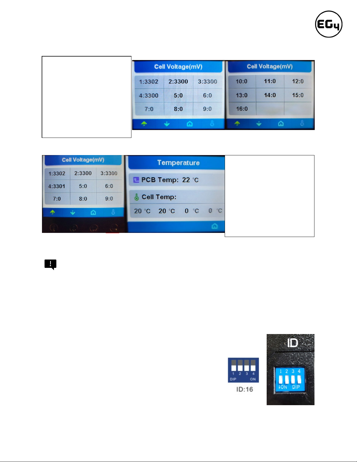
4.2.3 Cell information
4.2.4 Temperature Information
4.3 Communication Protocol Selection
Important
Only the host battery (Address 1) needs to be set to the inverter protocol; all other batteries must have
unique addresses starting at address 2 and ascending in chronological order. You must connect the
CAN/RS485 port of the host battery to your inverter’s (or communication device’s) BMS communication
port. Batteries in series (48V configuration max) will lose the ability to communicate, so protocols do
not need to be set.
4.3.1 Protocol Change/Selection Procedure
1. Power off all battery DC breakers and BMS power buttons. Ensure that the
voltage between positive and negative busbars is 0V.
2. The inverter protocol can only be changed with the host
battery temporarily set to address 16 (all dials down). After
the dial is changed, restart the battery (with only the BMS
power button) for the settings to take effect. (See image on
right.)
Press "Enter" on the Cell
Voltage page to view the
temperature information of
the PCB and the cells (Shown
in °C)
Note: There are only 2
temperature sensors
distributed evenly among the 4
packs.
Page 1
Page 2
Check individual cell voltage
by pressing the “Enter” button
on the main page (shown in
mV).There are 2 pages.
Pressing “Up” and “Down”
changes the page.
Note: 12V module only
displays 4 cells due to 4 packs
being in parallel (4s4p config.).

14
3. On the host battery, press and hold Enter for 5 seconds to enter the “Protocol Setting.”
4. Select the corresponding RS485 program or CAN program, and press Enter.
Note: The only supported inverter protocol at this time is for 12V Victron systems.
5. Press the “Return”key to return to the main interface.
6. Change the host DIP switch address back to address 1. (See image on right.)
7. Power cycle the host battery, and the BMS will correspond to the protocol selected.
4.4 BMS Tools Installation and Interfacing
The PC software “BMS Tools” provides real-time battery analysis and diagnostics. The battery cannot
communicate with BMS Tools and a closed loop inverter at the same time.
4.4.1 Downloading and Installing BMS Tools
1. Visit eg4electronics.com/downloads to get the latest version of the software for free. It can be
found in the “Software and Drivers” section.
3
4
1
2

15
2. Once downloaded, locate the file. (This is typically in the Downloads folder.)
3. Right click on the folder and click “Extract All.” Verify the location the file will be extracted to for
future reference. Check the box “Show extracted files when complete” and click on “Extract.”
3
1
2
4
1
2

16
4. Open the folder to access BMS_TOOLS. Right click and click “Run as administrator.” You may see
a popup for Microsoft Defender appear. Click “More info,” and then click “Run anyway.”
5. You will be brought to the main page of BMS Tools.
3
1
2

17
4.4.2 Interfacing with BMS Tools
1. While all power is off, set the DIP switch
ID address of the battery to Address 16.
2. Connect your USB cable to your PC and
to the RS485 port on the battery.
3. Power on the battery.
4. In the search bar at the bottom of the PC
screen, type “Device Manager.” Open
this application, and double click on
“Ports” to look for the COM port the
battery is in. (See image below.)
1
2
3
4
1
2
3

18
5. Open BMS Tools. Under “Monitor Status,” verify “COM”matches the battery COM from the
previous “Ports”list. Verify “Baud Rate”is set to 9600, and “PACK ID”is set to 16, then click
“SearchDevice.” After about 30 seconds, BMS Tools will begin the monitoring process and
pull real-time data from the BMS.
6. To review these steps, please watch our step-by-step guide at
https://youtu.be/Axhc8_22Go0.
4.4.3 Interface menu definition
Warning
Although there are multiple tabs in the BMS Tools software, the following tabs should not be tampered
with as any unauthorized changes will void the warranty of this product and risk damaging and/or
rendering the product permanently inoperable.
•BMS Parameter
•BMS Control
•Software Parameter
If you are experiencing any issues with the battery module or the BMS, please contact your distributor
for assistance or troubleshooting steps.
1
2

19
Interface menu definition
Item
Definition
BMS Monitoring
Real-time data and status monitoring of the BMS (see Section 5.2.1:
Warning and protect status definitions)
BMS Parameter
BMS parameter setting management (restricted, unauthorized
changes will void warranty)
BMS Control
Control state management of BMS (restricted, unauthorized
changes will void warranty)
BMS Datalog BMS operation data logging to PC (for manufacturer use)
Historical Record Real time BMS operation data records (exportable)
Communication Record of sending and receiving of battery pack data (exportable)
Software Parameter
Software configuration, settings, and language selection
(restricted, unauthorized changes will void warranty)
4.5 Installing and using EG4 Bluetooth App
1. Download the app using the QR
codes here. (You may need to
enable “Allow install from
unknown sources” on Android
devices.)
iOS App
Android App
Other manuals for EG4-LL
1
Table of contents
Other EG4 Camera Accessories manuals


