1Read Instructions - All the safety and operating
instructions should be read before the unit is
operated.
2Retain Instructions - The safety and operating
instructions should be retained for future
reference.
3Heed Warnings - All warnings on the unit and in
the operating instructions should be adhered to.
4Follow Instructions - All operating and user
instructions should be followed.
5 Electrical Connections - Only a qualied
electrician should make electrical connections..
6Attachments - Do not use attachments not
recommended by the product manufacturer as
they may cause hazards.
7Cable Runs - All cable runs must be within
permissible distance
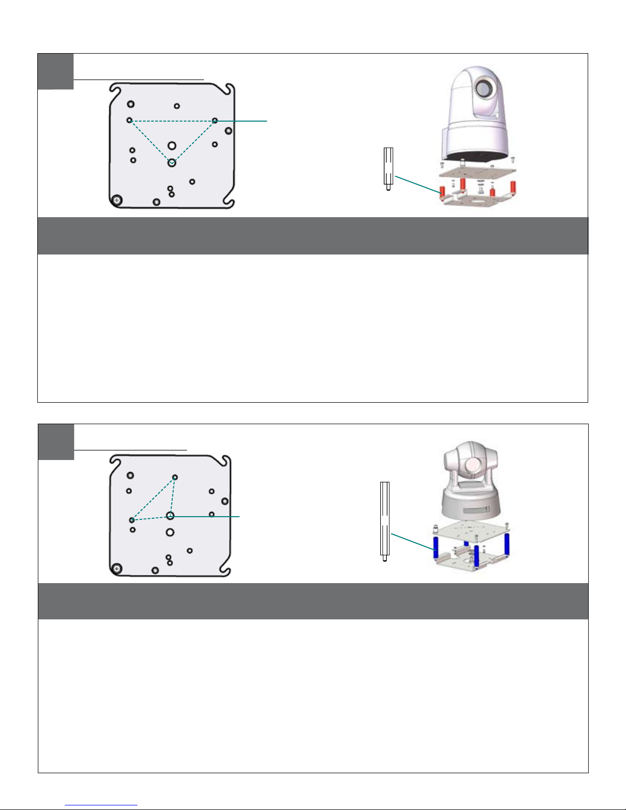
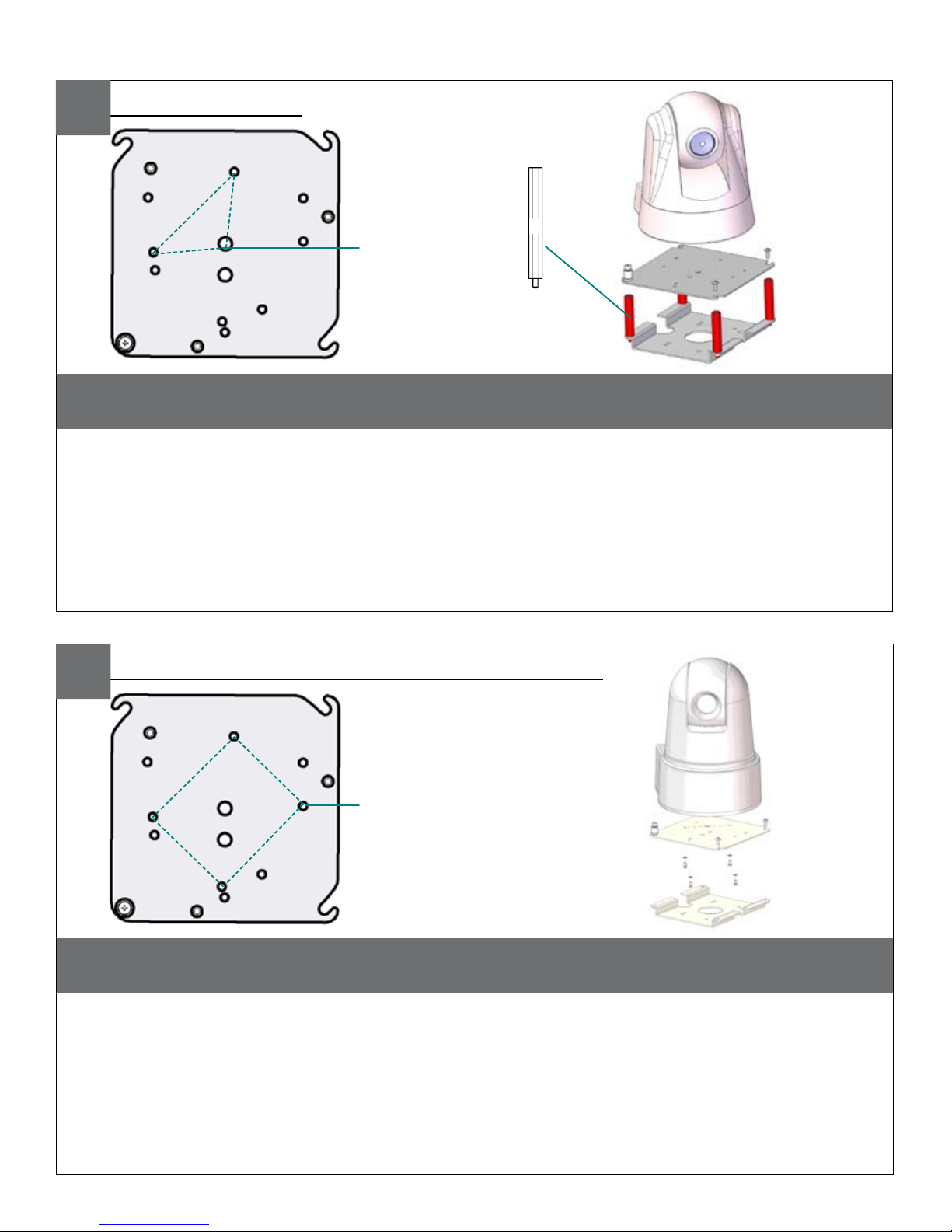
8Mounting - This unit must be properly and securely
mounted to a supporting structure capable of
sustaining the weight of the unit.
Accordingly:
a. The installation should be made by a qualied
installer.
b. The installation should be in compliance with
local codes.
c. Care should be exercised to select suitable
hardware to install the unit, taking into
account both the composition of the mounting
surface and the weight of the unit.
Be sure to periodically examine the unit and the
supporting structure to make sure that the integrity
of the installation is intact. Failure to comply with the
foregoing could result in the unit separating from the
support structure and falling, with resultant damages or
injury to anyone or anything struck by the falling unit.
IMPORTANT SAFEGUARDS SAFETY PRECAUTIONS
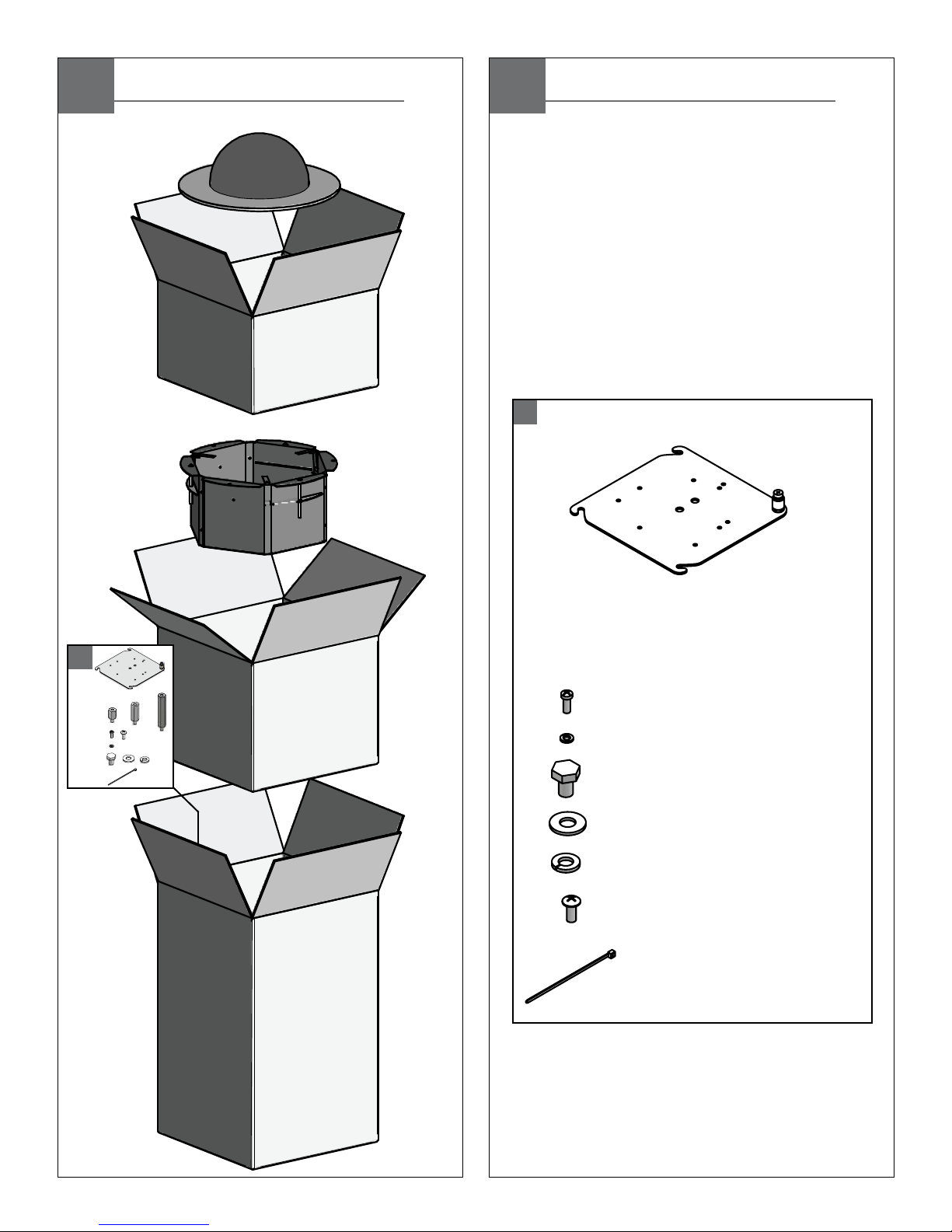
UNPACKING
SERVICE
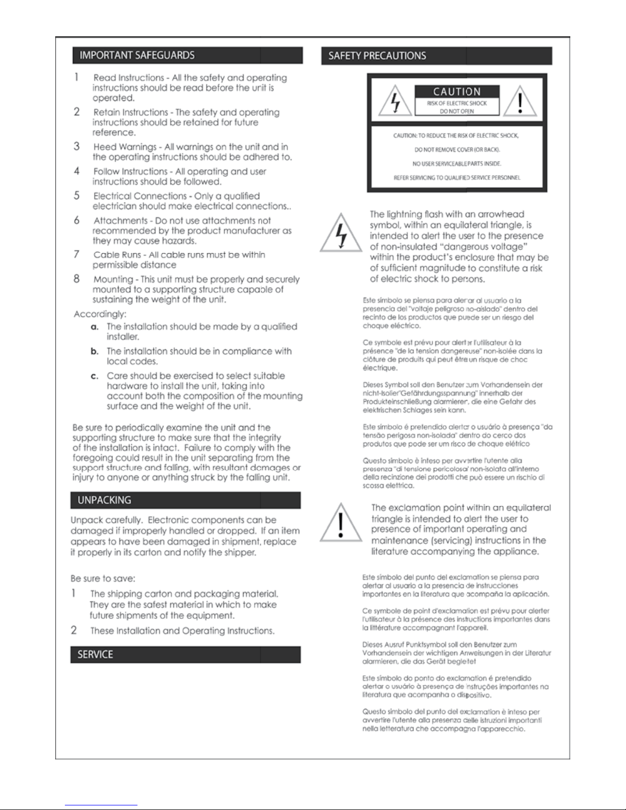
CAUTION
RISK OF ELECTRIC SHOCK
DO NOT OPEN
CAUTION: TO REDUCE THE RISK OF ELECTRIC SHOCK,
DO NOT REMOVE COVER (OR BACK).
NO USER SERVICEABLE PARTS INSIDE.
REFER SERVICING TO QUALIFIED SERVICE PERSONNEL
The lightning ash with an arrowhead
symbol, within an equilateral triangle, is
intended to alert the user to the presence
of non-insulated “dangerous voltage”
within the product’s enclosure that may be
of sufcient magnitude to constitute a risk
of electric shock to persons.
The exclamation point within an equilateral
triangle is intended to alert the user to
presence of important operating and
maintenance (servicing) instructions in the
literature accompanying the appliance.
Unpack carefully. Electronic components can be
damaged if improperly handled or dropped. If an item
appears to have been damaged in shipment, replace
it properly in its carton and notify the shipper.
Be sure to save:
1The shipping carton and packaging material.
They are the safest material in which to make
future shipments of the equipment.
2These Installation and Operating Instructions.
If technical support or service is needed, contact Sony
at the following number:
TECHNICAL SUPPORT
8:15AM to 7:30PM (Eastern Time)
1-800-883-6817
©2007 Sony Corporation
If technical support or service is needed, contact
Sony at the following number.
TECHNICAL SUPPORT
8:15 AM to 7:30 PM
(EASTERN TIME)
1-800-883-6817


 User manual")