manuals.online logo
Brands
  1. Home
  2. •
  3. Brands
  4. •
  5. Lippert
  6. •
  7. Automobile Accessories
  8. •
  9. Lippert SolidStep Gen 2 Installation instructions

Lippert SolidStep Gen 2 Installation instructions

1
lippertcomponents.com 574-537-8900 Rev: 03.17 - SolidStep™Gen 2
SolidStep™Gen 2
Installation and Owner’s Manual
(For Aftermarket Applications)
Table of Contents
Introduction ............................................ 2
Resources Required ................................... 2
Installation .............................................. 2
Prior to installation ..................................... 2
SolidStep Installation .................................. 2
Leg Extension Adjustment ............................ 4
SolidStep™
Gen 2
Installation and
Owner’s Manual
(For Aftermarket Applications)
Part # SolidStep* # of Treads Suggested Floor Height
678024 26” 4 35” - 44”
678025 28” 4 35” - 44”
678027 30” 4 35” - 44”
678028 32” 4 35” - 44”
678031 34” 4 35” - 44”
678036 36” 4 35” - 44”
678040 26” 3 27” - 36”
678041 28” 3 27” - 36”
678044 30” 3 27” - 36”
678047 32” 3 27” - 36”
Open the RV door and measure the inside width of the
door frame. The correct size SolidStep will be the nearest
even number rounded up.
Example: If the inside width is 25-5/16”, round up to a 26”
SolidStep.
* The measurement of the inside width of the door frame rounded up to the nearest even number is the corresponding
SolidStep required.
2
lippertcomponents.com 574-537-8900 Rev: 03.17 - SolidStep™Gen 2
SolidStep™Gen 2
Installation and Owner’s Manual
(For Aftermarket Applications)
Introduction
The SolidStep™GEN 2 is a trailer entry step assembly that
can be mounted to the side of any trailer, providing an ease
of entry regardless of level ground. The suggested oor
height range should be between 35”- 44” for a four-step
tread and 27”- 36” for a three-step tread.
NOTE: The oor of the trailer must have sufcient backing
material for securing the SolidStep GEN 2.
FAILURE TO FOLLOW THE INSTRUCTIONS PROVIDED
IN THIS MANUAL MAY RESULT IN DEATH, SERIOUS
INJURY, TRAILER DAMAGE, OR VOIDING OF THE
COMPONENT WARRANTY.
ALWAYS WEAR EYE PROTECTION WHEN
PERFORMING SERVICE OR MAINTENANCE TO THE
TRAILER. OTHER SAFETY EQUIPMENT TO CONSIDER
WOULD BE HEARING PROTECTION, GLOVES AND
POSSIBLY A FULL FACE SHIELD, DEPENDING ON THE
NATURE OF THE SERVICE.
NO REPAIRS SHOULD BE ATTEMPTED BY ANYONE
OTHER THAN A QUALIFIED PROFESSIONAL.
THE DEPLOYMENT AND RETRACTION OF THE
STEP ASSEMBLY CAN CAUSE INJURY IF PROPER
PRECAUTIONS ARE NOT TAKEN. THE STEP ASSEMBLY
WAS DESIGNED FOR AN OPERATIONAL WEIGHT
RATING OF 400 LBS.
MOVING PARTS CAN PINCH, CRUSH OR CUT. KEEP
CLEAR AND USE CAUTION.
Resources Required
Installation
Prior to installation
1. Verify that the trailer is on level or near-level ground.
2. If the trailer oor has a step threshold transition piece, it
should be removed now.
NOTE: The door and frame have been removed for clarity.
SolidStep Installation
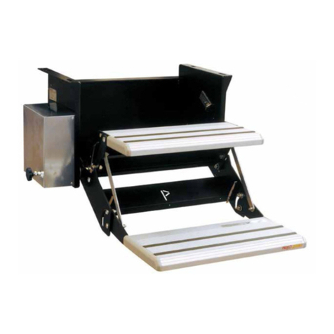
1. Place the SolidStep GEN 2 assembly inside the door
frame and verify with a tape measure that the SolidStep
GEN 2 is centered in the door frame.
NOTE: Verify that the SolidStep GEN 2 mounting plate
(Fig.1A) is ush against the sidewall of the trailer.
2. Remove the 2 plastic caps from the alignment cover
holes on the mounting plate (Fig.1B).
3. With the step assembly in the extended position (Fig.1),
install 2 fasteners, either #10 - 1 ½” self-tapping screws
(laminate oor), or #10 - 1 ½” wood screws (wood oor)
into the mounting plate via the 2 access holes (Fig.1B)
located in the top of the mounting plate.
4. Once the two fasteners are inserted, carefully lift the
step assembly to the upright, stored position. The latching
mechanism will engage after adjustment. At this point,
have 1 extra person hold the step assembly from inside the
trailer.
Fig.1
A
B
• 1 to 2 Persons
• Cordless or Electric Drill
or Screw Gun
• Appropriate Drive Bits
• Flat Head Screwdriver
• 3/8” Wrench
• Tape Measure
3
lippertcomponents.com 574-537-8900 Rev: 03.17 - SolidStep™Gen 2
SolidStep™Gen 2
Installation and Owner’s Manual
(For Aftermarket Applications)
5. If adjustment is required, loosen the 2 bolts (Fig.2A) on
both sides of the transport lock. This allows for up to ½” of
adjustment either way.
Fig.2
A
6. Once in the correct position tighten the bolts.
7. Once the transport locks have been adjusted, test the
functionality by shaking the step assembly to simulate road
vibration.
8. Engage and disengage the transport lock (Fig.3A) to
ensure the latch anges do not scrape against the door
frame.
DO NOT OVER TIGHTEN THE BOLTS, AS DOING SO
MAY DAMAGE THE THREADS IN THE SHEET METAL
OR CAUSE THE BOLT HEADS TO BREAK OFF.
Fig.3
A
9. If necessary, make minor adjustments by loosening the
two #10 self-tapping fasteners (Fig.1B) previously installed
in the mounting plate.
10. Using 8 additional fasteners (Fig.4A), either #10 - 1 ½”
self-tapping screws (laminate oor) or #10 - 1 ½” wood screws
(wood oor), fasten the hinge plate to the oor of the trailer
(Fig.4B). Use the horizontal slots (Fig.4C) to make additional
small adjustments of the step assembly in the doorway.
Fig.4
A
BC
11. Extend the step assembly and install the 2 provided
plastic caps into the alignment cover holes on the mounting
plate (Fig.5A).
Fig.5
A
DO NOT ATTEMPT TO LOCK THE STEP IN PLACE,
AS THE LATCHING MECHANISM MAY NEED TO
BE ADJUSTED TO THE PROPER LEFT-RIGHT
ORIENTATION AND TIGHTENED IN POSITION BEFORE
USING THE TRANSPORT LOCK. ATTEMPTING TO
ENGAGE THE TRANSPORT LOCK WITHOUT PROPER
ADJUSTMENT MAY CAUSE DAMAGE TO THE DOOR
FRAME OR STEP ASSEMBLY.
4
lippertcomponents.com 574-537-8900 Rev: 03.17 - SolidStep™Gen 2
SolidStep™Gen 2
Installation and Owner’s Manual
(For Aftermarket Applications)
Leg Extension Adjustment
Leg Extensions are secured with a Quick Release Clevis
Pin. Independent adjustments can be made to each leg
extension in 1.00” increments by moving the inner leg up or
down to achieve optimum ground surface angle.
1. To extend the inner leg (Fig.6B):
A. Remove the Quick Release Clevis Pin (Fig.6C) from
the tube and the slot in the angle.
B. Extend the inner leg (Fig.6B) to the ground and at an
angle so the steps are parallel to the ground and are level
C. Replace the Quick Release Clevis Pin (Fig.6C) in the
tube and slot closest to where the inner leg and the outer
leg (Fig.6A) meet.
2. To retract the inner leg (Fig.6B):
A. Remove the Quick Release Clevis Pin (Fig.6C) from
the tube and slot.
B. Retract the inner leg.
C. Replace the Quick Release Clevis Pin in the tube and
slot.
The step assembly is shown in the upright, stored position
in Fig. 7.
Fig.6
Fig.7
A
B
C
Manual information may be distributed as a complete
document only, unless Lippert Components provides
explicit consent to distribute individual parts.
All manual information is subject to change without
notice. Revised editions will be available for free
download at www.lippertcomponents.com. Manual
information is considered factual until made obsolete by
a revised version.
Please recycle all obsolete materials and contact Lippert
Components with concerns or questions.

Other Lippert Automobile Accessories manuals

Lippert Curt 18110 User manual

Lippert

Lippert Curt 18110 User manual

Lippert RV Instruction Manual

Lippert

Lippert RV Instruction Manual

Lippert SolidStep 4.0 User manual

Lippert

Lippert SolidStep 4.0 User manual

Lippert Curt 18150 User manual

Lippert

Lippert Curt 18150 User manual

Lippert 10570 Instruction manual

Lippert

Lippert 10570 Instruction manual

Lippert FLYSCREEN N Series User manual

Lippert

Lippert FLYSCREEN N Series User manual

Lippert LUVERNE 401720 User manual

Lippert

Lippert LUVERNE 401720 User manual

Lippert Curt 16613 User manual

Lippert

Lippert Curt 16613 User manual

Lippert Sway Command 1.5 User manual

Lippert

Lippert Sway Command 1.5 User manual

Lippert Stargazer Spirit XTR Skylight User manual

Lippert

Lippert Stargazer Spirit XTR Skylight User manual

Lippert Kwikee Step Well Cover User manual

Lippert

Lippert Kwikee Step Well Cover User manual

Lippert Vela User manual

Lippert

Lippert Vela User manual

Lippert Curt 13496 User manual

Lippert

Lippert Curt 13496 User manual

Lippert Vela Pop Up Use and care manual

Lippert

Lippert Vela Pop Up Use and care manual

Lippert TI-276 User manual

Lippert

Lippert TI-276 User manual

Lippert Level-up User manual

Lippert

Lippert Level-up User manual

Lippert CURT 45937 User manual

Lippert

Lippert CURT 45937 User manual

Lippert Stargazer Spirit XTR User manual

Lippert

Lippert Stargazer Spirit XTR User manual

Lippert SMART BED UNIVERSAL KIT User manual

Lippert

Lippert SMART BED UNIVERSAL KIT User manual

Lippert Power Step 2.0 User manual

Lippert

Lippert Power Step 2.0 User manual

Lippert ARIES S224050 User manual

Lippert

Lippert ARIES S224050 User manual

Lippert 45940-85 User manual

Lippert

Lippert 45940-85 User manual

Lippert Vela Pop Up User manual

Lippert

Lippert Vela Pop Up User manual

Lippert Thule 5200 Use and care manual

Lippert

Lippert Thule 5200 Use and care manual

Popular Automobile Accessories manuals by other brands

Mi CC06ZM user manual

Mi

Mi CC06ZM user manual

Safe Fleet Prime Design VRR-FT21G-ST Assembly instructions

Safe Fleet

Safe Fleet Prime Design VRR-FT21G-ST Assembly instructions

Warn 70045 installation instructions

Warn

Warn 70045 installation instructions

Rightline Gear 4x4 Duffle Bag installation guide

Rightline Gear

Rightline Gear 4x4 Duffle Bag installation guide

Team Tech Offroad TACOMA HOOD STRUT Kit Installation

Team Tech Offroad

Team Tech Offroad TACOMA HOOD STRUT Kit Installation

TrailFX 23004X quick start guide

TrailFX

TrailFX 23004X quick start guide

Kuda-Phonebase 291750 Installation instruction

Kuda-Phonebase

Kuda-Phonebase 291750 Installation instruction

Directed Directechs DB3 installation guide

Directed

Directed Directechs DB3 installation guide

Connects2 CAM-MB2-AD instruction manual

Connects2

Connects2 CAM-MB2-AD instruction manual

Tactik 12011.010 Series installation manual

Tactik

Tactik 12011.010 Series installation manual

FH Group FB078102 instruction manual

FH Group

FH Group FB078102 instruction manual

Havis-Shields KK-K9-D22-K installation instructions

Havis-Shields

Havis-Shields KK-K9-D22-K installation instructions

KAPSCH Janus HOTPass Mounting instructions

KAPSCH

KAPSCH Janus HOTPass Mounting instructions

Yakima ROC 4 manual

Yakima

Yakima ROC 4 manual

Husky 31853 Assembly, Installation, Operation and Maintenance Instructions

Husky

Husky 31853 Assembly, Installation, Operation and Maintenance Instructions

Acrosser Technology AR-B6005 user manual

Acrosser Technology

Acrosser Technology AR-B6005 user manual

Thule Rapid System 1550 instructions

Thule

Thule Rapid System 1550 instructions

Needit Park Lite user manual

Needit

Needit Park Lite user manual

manuals.online logo
manuals.online logoBrands
  • About & Mission
  • Contact us
  • Privacy Policy
  • Terms and Conditions

Copyright 2025 Manuals.Online. All Rights Reserved.