manuals.online logo
Brands
  1. Home
  2. •
  3. Brands
  4. •
  5. Pepperl+Fuchs
  6. •
  7. Switch
  8. •
  9. Pepperl+Fuchs LVL-M4 User manual

Pepperl+Fuchs LVL-M4 User manual

Instruction Manual
1. Marking
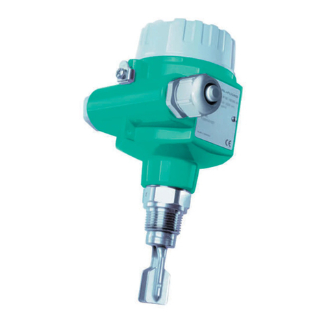
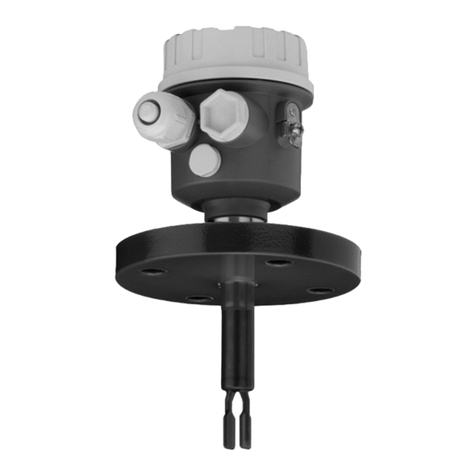
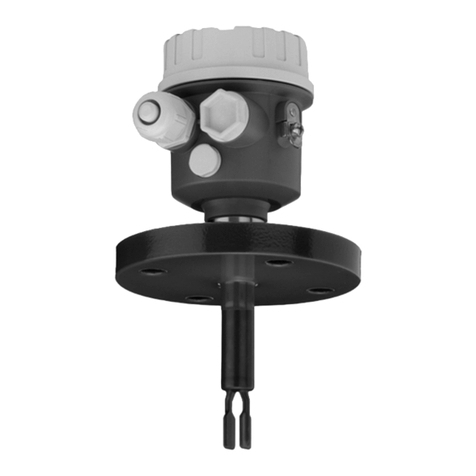
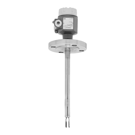
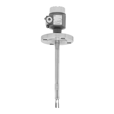
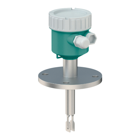
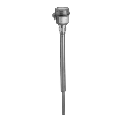
Vibration Limit Switch for Liquids
LVL-M4
ATEX certificate: CSANe 23ATEX1157X
ATEX marking:
1 II 1/2G Ex db IIC T6...T1 Ga/Gb
1 II 2G Ex db IIC T6...T1 Gb
1 II 1/2D Ex ta/tb IIIC Txxx°C Da/Db
1 II 2D Ex tb IIIC Txxx°C Db
IECEx certificate: IECEx CSAE 23.0044X
IECEx marking:
Ex db IIC T6...T1 Ga/Gb
Ex db IIC T6...T1 Gb
Ex ta/tb IIIC Txxx°C Da/Db
Ex tb IIIC Txxx°C Db
Pepperl+Fuchs Group
Lilienthalstraße 200, 68307 Mannheim, Germany
Internet: www.pepperl-fuchs.com
2. Device Versions
Device type Basic
specifications
Optional
specifications
LVL-M4 -XXXXXX-XXXXXX-
XX
+XX
The X-marked letters of the type code are placeholders for versions of the
device.
The following specifications reproduce an extract from the product
structure and are used to assign.
Basic specifications
Option Type of probe
A Compact version
B Short tube version
C Tube extension
Option Sensor length, material
A Compact version, Alloy C22
B Compact version, 316L
C Short tube version, Alloy C22
D Short tube version, 316L
E Tube extension, length L in mm, Alloy C22,
Ra < 3.2 μm/126 μinch
F Tube extension, length L in mm, 316L,
Ra < 3.2 μm/126 μinch
G Tube extension, length L in inch, Alloy C22,
Ra < 3.2 μm/126 μinch
H Tube extension, length L in inch, 316L,
Ra < 3.2 μm/126 μinch
Option Housing, material
A Single compartment, aluminum, coated
D Dual compartment, L-shape, aluminum,
coated
G Single compartment, 316L, cast
Option Electrical connection
F Thread M20, IP66/68, NEMA type 4X/6P
G 1Thread G1/2, IP66/68, NEMA type 4X/6P
I Thread NPT3/4, IP66/68, NEMA type 4X/6P
1 Reduction M20x1.5 to G1/2 enclosed
Option Application, temperature
A Process: max. 150 °C/302 °F, max. 64 bar
B Process: max. 150 °C/302 °F, max. 100 bar
Option Electrical output
A FEL61, 2-wire, 19 to 253 V AC with test
button
B FEL64DC, relay DPDT, 9 V DC to 20 V DC,
contact 253 V/6 A with test button
E FEL62, 3-wire PNP, 10 V DC to 55 V DC
with test button
N FEL64, relay DPDT, 19 V AC to 253 V
AC/19 V DC to 55 V DC, contact 253 V/6 A
with test button
M FEL68, 2-wire NAMUR with test button
Option Display, operation
A Without display, switch
B 2LED module VU120 visible from the outside,
switch
2 Only in connection with feature Electrical output, option B, E, N and feature Housing, material,
option A, D
Option Approval
ES ATEX/IEC II 1/2G, 2G Ex db IIC T6 Ga/Gb, II
1/2D, 2D Ex ta/tb IIIC Da/Db
Optional specifications
Option Test, certificate, declaration
U1 3Ambient temperature -50 °C/-58 °F
U2 3Ambient temperature -60 °C/-76 °F
3 Only in connection with feature Electrical output, option B, E, N, M and feature Display,
operation, option A
Option Sensor design
DF Pressure tight feed through (second line of
defense)
TD Temperature spacer
Option Accessory mounted
BL 4Bluetooth module VU121
VB 5Bluetooth module VU121 for NAMUR output
4 Only in connection with feature Electrical output, option A, B, E, N, feature Housing, material,
option A, D and feature Display, operation, option A
5 Only in connection with feature Electrical output, option M, feature Housing, material,
option A, D and feature Display, operation, option A
Option Accessory enclosed
ST 6Test magnet
WP 7Weather protection cover, plastic
WS 8Weather protection cover, 316L
6 Only in connection with feature Electrical output, option B, E, N, M
7 Only in connection with feature Housing, material, option A, G
8 Only in connection with feature Housing, material, option D
3. Target Group, Personnel
Responsibility for planning, assembly, commissioning, operation,
maintenance, and dismounting lies with the plant operator.
The personnel must be appropriately trained and qualified in order to carry
out mounting, installation, commissioning, operation, maintenance, and
dismounting of the device. The trained and qualified personnel must have
read and understood the instruction manual.
Prior to using the product make yourself familiar with it. Read the
instruction manual carefully.
4. Reference to Further Documentation
Observe directives, standards, and national laws applicable to the
intended use and the operating location.
The corresponding datasheets, manuals, declarations of conformity, EU-
type examination certificates, certificates, control drawings, and
temperature tables if applicable are an integral part of this document. You
can find this information under www.pepperl-fuchs.com.
For specific device information such as the year of construction,
scan the QR code on the device. As an alternative, enter the serial number
in the serial number search at www.pepperl-fuchs.com.
Refer to the relevant EU-type examination certificate to see the
relationship between the connected circuit type, the maximum permitted
ambient temperature, the temperature class, and the effective inner
reactances.
If you use the device in safety-related applications, observe the
requirements for functional safety. You can find these requirements in the
functional safety documentation under www.pepperl-fuchs.com.
DOCT-8396 / 2023-08 1 / 2
5. Intended Use
The device is only approved for appropriate and intended use.
Ignoring these instructions will void any warranty and absolve
the manufacturer from any liability.
The device is a vibration limit switch for minimum or maximum detection in
tanks, containers and piping with all types of liquids
Use the device only within the specified ambient and operating conditions.
Only use the device in media to which the process-contacting materials
of the device are sufficiently resistant.
The EU-type examination certificate in accordance with ATEX Directive
applies only to the use of apparatus under atmospheric conditions.
The device can be used in hazardous areas containing gas, vapor, and
mist.
The device can be used in hazardous areas containing combustible dust.
If you use the device in safety-related applications, observe the
information for safety function and safe state.
6. Improper Use
Protection of the personnel and the plant is not ensured if the device
is not used according to its intended use.
7. Mounting and Installation
Use appropriate protection measures in order to protect persons that have
contact with hazardous or toxic substances.
Do not mount a damaged or polluted device.
Mount the device in a way that the device is protected against mechanical
hazard.
If you expect dynamic loads, support the extension tube of the device.
Only use accessories specified by the manufacturer.
If you install the device in safety-related applications, observe the
requirements for functional safety.
Include the device into the equipotential bonding.
Avoid inadmissibly high electrostatic charge plastic surfaces.
Avoid inadmissibly high electrostatic charge of insulated capacities or
insulated metal parts.
Requirements for Cables and Connection Lines
Only use cables and connection lines with a temperature range
appropriate to the application.
Install cables and cable glands in a way that they are not exposed to
mechanical hazards.
Observe the minimum bending radius of the conductors.
Observe the permissible core cross section of the conductor.
Crimp wire end ferrules on the conductor ends.
When installing the conductors the insulation must reach
up to the terminal.
Close all unused cable glands with the appropriate sealing plugs.
Requirements for Hazardous Area
Observe the installation instructions according to IEC/EN 60079-14.
Refer to the temperature tables for the relationship between permitted
ambient temperature, range of application and temperature class.
The device may be installed in Zone 1.
The measuring equipment of the device may be installed in Zone 0.
If circuits with type of protection Ex i are operated with non-intrinsically
safe circuits, they must no longer be used as circuits with type of
protection Ex i.
Observe the respective peak values of the field device and the associated
apparatus with regard to explosion protection when connecting intrinsically
safe field devices with intrinsically safe circuits of associated apparatus
(verification of intrinsic safety). Also observe IEC/EN 60079-14 and
IEC/EN 60079-25.
Keep the separation distances between all non-intrinsically safe circuits
and intrinsically safe circuits according to IEC/EN 60079-14.
Basic specification, feature Housing, material, option A, D
Avoid impact effect or friction during mounting.
Optional specification, feature Accessory Enclosed, option WP
Avoid electrostatic charges which could result in electrostatic discharges
while installing, operating, or maintaining the device.
Optional specification, feature Accessory Enclosed, option WS
Include the device into the equipotential bonding.
Optional specification, feature Accessory Enclosed, option ST
The component is suitable for use in the explosion-hazardous area.
8. Operation, Maintenance, Repair
If you operate the device in safety-related applications, observe the
requirements for functional safety. In case of operating in low demand
mode, plan appropriate intervals for the proof test.
Do not use a damaged or polluted device.
The device is maintenance-free.
Do not repair, modify, or manipulate the device.
If there is a defect, always replace the device with an original device.
Connection or disconnection of energized circuits is only permitted in the
absence of a potentially explosive atmosphere.
Avoid inadmissibly high electrostatic charge plastic surfaces.
Avoid inadmissibly high electrostatic charge of insulated capacities or
insulated metal parts.
Basic specification, feature Housing, material, option A, D
Avoid impact effect or friction during operating.
Optional specification, feature Accessory Enclosed, option WP
Avoid electrostatic charges which could result in electrostatic discharges
while installing, operating, or maintaining the device.
Optional specification, feature Accessory Enclosed, option WS
Include the device into the equipotential bonding.
Optional specification, feature Accessory Enclosed, option ST
The component is suitable for use in the explosion-hazardous area.
Basic specification, feature Electrical Output, option M
If you equip the device with the Bluetooth® module, a battery is required.
Only remove or replace the battery in the non-explosion-hazardous area.
Observe the instruction manuals for the associated modules.
Return
Take the following precautions before you return the device to
Pepperl+Fuchs.
Remove all adhering residues from the device. These residues can be
hazardous to health.
Fill in the form Declaration of Contamination. You can find this form on
the product detail page at www.pepperl-fuchs.com.
Enclose the filled in Declaration of Contamination form with the device.
Pepperl+Fuchs can examine and repair a returned device, only if a
completed form is included in the return.
If needed, include special handling instructions with the device.
Specify the following information:
lChemical and physical characteristics of the product
lDescription of the application
lDescription of the error that occurred (specify error code if possible)
lOperating time of the device
9. Delivery, Transport, Disposal
Check the packaging and contents for damage.
Check if you have received every item and if the items received are the
ones you ordered.
Store the device in a clean and dry environment. The permitted ambient
conditions must be considered, see datasheet.
The device, built-in components, packaging, and any batteries
contained within must be disposed in compliance with the applicable laws
and guidelines of the respective country.
DOCT-8396 / 2023-08 2 / 2

Other manuals for LVL-M4

9

Other Pepperl+Fuchs Switch manuals

Pepperl+Fuchs Vibracon LVL-M1 User manual

Pepperl+Fuchs

Pepperl+Fuchs Vibracon LVL-M1 User manual

Pepperl+Fuchs SIL LVL-M4 User manual

Pepperl+Fuchs

Pepperl+Fuchs SIL LVL-M4 User manual

Pepperl+Fuchs Vibracon LVL-M1 User manual

Pepperl+Fuchs

Pepperl+Fuchs Vibracon LVL-M1 User manual

Pepperl+Fuchs Vibracon LVL-B1 Reference guide

Pepperl+Fuchs

Pepperl+Fuchs Vibracon LVL-B1 Reference guide

Pepperl+Fuchs KFD0-SD2-Ex2.1045 User manual

Pepperl+Fuchs

Pepperl+Fuchs KFD0-SD2-Ex2.1045 User manual

Pepperl+Fuchs Vibracon LVL-M2C User manual

Pepperl+Fuchs

Pepperl+Fuchs Vibracon LVL-M2C User manual

Pepperl+Fuchs LCL2 Reference guide

Pepperl+Fuchs

Pepperl+Fuchs LCL2 Reference guide

Pepperl+Fuchs SI00114O-H User manual

Pepperl+Fuchs

Pepperl+Fuchs SI00114O-H User manual

Pepperl+Fuchs Vibracon LVL-M2C User manual

Pepperl+Fuchs

Pepperl+Fuchs Vibracon LVL-M2C User manual

Pepperl+Fuchs HiC284 Series User manual

Pepperl+Fuchs

Pepperl+Fuchs HiC284 Series User manual

Pepperl+Fuchs LVL-M4 User manual

Pepperl+Fuchs

Pepperl+Fuchs LVL-M4 User manual

Pepperl+Fuchs Vibracon LVL-M Series User manual

Pepperl+Fuchs

Pepperl+Fuchs Vibracon LVL-M Series User manual

Pepperl+Fuchs LVL-M4 User manual

Pepperl+Fuchs

Pepperl+Fuchs LVL-M4 User manual

Pepperl+Fuchs HiC2832R1 User manual

Pepperl+Fuchs

Pepperl+Fuchs HiC2832R1 User manual

Pepperl+Fuchs VISOLUX ML7-55 User manual

Pepperl+Fuchs

Pepperl+Fuchs VISOLUX ML7-55 User manual

Pepperl+Fuchs LVL-M4 Reference guide

Pepperl+Fuchs

Pepperl+Fuchs LVL-M4 Reference guide

Pepperl+Fuchs ARS B2 IC Series User manual

Pepperl+Fuchs

Pepperl+Fuchs ARS B2 IC Series User manual

Pepperl+Fuchs Vibracon LVL-M H Series User manual

Pepperl+Fuchs

Pepperl+Fuchs Vibracon LVL-M H Series User manual

Pepperl+Fuchs PROFINET IO Power Hub User manual

Pepperl+Fuchs

Pepperl+Fuchs PROFINET IO Power Hub User manual

Pepperl+Fuchs Ethernet-APL Series User manual

Pepperl+Fuchs

Pepperl+Fuchs Ethernet-APL Series User manual

Pepperl+Fuchs RocketLinx ICRL2-U-5RJ45-DIN User manual

Pepperl+Fuchs

Pepperl+Fuchs RocketLinx ICRL2-U-5RJ45-DIN User manual

Pepperl+Fuchs LVL-M4 User manual

Pepperl+Fuchs

Pepperl+Fuchs LVL-M4 User manual

Pepperl+Fuchs LCL1 User manual

Pepperl+Fuchs

Pepperl+Fuchs LCL1 User manual

Pepperl+Fuchs LVL-M4 Manual

Pepperl+Fuchs

Pepperl+Fuchs LVL-M4 Manual

Popular Switch manuals by other brands

Allen-Bradley Guard master IMP Series installation instructions

Allen-Bradley

Allen-Bradley Guard master IMP Series installation instructions

schmersal AZM300B-I2-ST-1P2P-A-DU instructions

schmersal

schmersal AZM300B-I2-ST-1P2P-A-DU instructions

SilverStone SST-ES02-USB quick start guide

SilverStone

SilverStone SST-ES02-USB quick start guide

Allied Telesis AT-8600 Series release note

Allied Telesis

Allied Telesis AT-8600 Series release note

Endress+Hauser Liquiphant FTL33 IO-Link Brief operating instructions

Endress+Hauser

Endress+Hauser Liquiphant FTL33 IO-Link Brief operating instructions

Cisco Nexus 9372TX Hardware installation guide

Cisco

Cisco Nexus 9372TX Hardware installation guide

urmet domus Yokis ABE2BPP manual

urmet domus

urmet domus Yokis ABE2BPP manual

Vertiv SC 940 user manual

Vertiv

Vertiv SC 940 user manual

Pylon Technologies LV-Hub Series product manual

Pylon Technologies

Pylon Technologies LV-Hub Series product manual

Progressive Dynamics PD5200 Installation and operation guide

Progressive Dynamics

Progressive Dynamics PD5200 Installation and operation guide

S&C Mark V Instructions For Field Assembly and Installation

S&C

S&C Mark V Instructions For Field Assembly and Installation

Unilamp Luzense RADIM RF instruction manual

Unilamp

Unilamp Luzense RADIM RF instruction manual

HP HPE 5140 Product End-of-Life Disassembly Instructions

HP

HP HPE 5140 Product End-of-Life Disassembly Instructions

Digital Equipment EtherWORKS Switch 8T/TX Installation and configuration

Digital Equipment

Digital Equipment EtherWORKS Switch 8T/TX Installation and configuration

Linksys EFAH05W Specifications

Linksys

Linksys EFAH05W Specifications

Quintum Tenor AXE1600 release note

Quintum

Quintum Tenor AXE1600 release note

Avocent DSR Series DSR1030 Installer/user guide

Avocent

Avocent DSR Series DSR1030 Installer/user guide

H3C S7500 Series Operation manual

H3C

H3C S7500 Series Operation manual

manuals.online logo
manuals.online logoBrands
  • About & Mission
  • Contact us
  • Privacy Policy
  • Terms and Conditions

Copyright 2025 Manuals.Online. All Rights Reserved.