Eickemeyer MAGIC 500 User manual
1
Eickemeyer
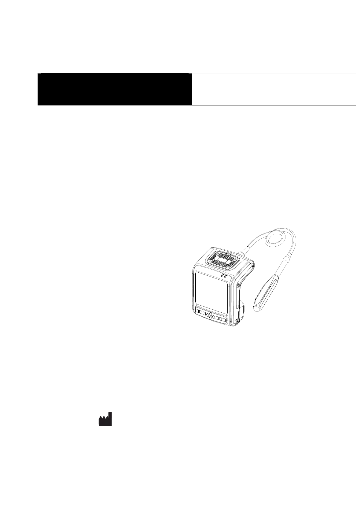
MAGIC 500 Ultrasonic Diagnostic Instruments
User’s Manual
Information for Users
Users shall carefully read through this manual and fully understand the text before operating the equipment. This manual shall
be placed easy of access for future reference; otherwise it may cause instrument damage or person injury.

2
Intellectual Property Information
Company Eickemeyer edizintechnik fuer Tieraerzte KG (hereinafter referred to as Eickemeyer) has the copyright of this
user’s manual and reserves the right to keep it confidential. This user’s manual shall be used for the sole purpose of operation,
maintenance and servicing of Eickemeyer’s products.
This user’s manual and intellectual property right (including copyright) herewith included is property of Eickemeyer. No
persons may use, disclose or allow a third party to obtain by any means any of the information contained herein without prior
written consent of Eickemeyer. No persons may reproduce this user’s manual, in whole or in part, including but not limited to
photography, photocopy, reprint or translation into any other language without prior written consent of Eickemeyer.
AGIC 500 - This is registered trade mark of Eickemeyer Company.
Eickemeyer is the sole authority for the interpretation of this user’s manual.
Eickemeyer may revise this manual without prior notice.
Eickemeyer may revise its technical process without prior notice.
Eickemeyer may modify specifications of the product without prior notice.
Liability and Disclaimer Statement
Eickemeyer does not guarantee the correctness of information contained in this manual. Eickemeyer bears no responsibility
for the use of this user’s manual, including but not limited to responsibilities of implied marketability or merchantability applicable
to the product for a particular use.
Eickemeyer shall be responsible for the safety, reliability and proper performance of this equipment on condition that the
assembly, extension, readjustment, modification or service of the equipment herewith related is done by technical personnel
authorized or approved by Eickemeyer edizintechnik fuer Tieraerzte KG;
The electric equipment is consistent with relevant national standards and the equipment is operated in compliance with the
operation guidance.
Eickemeyer does not guarantee the safety, reliability and proper performance of the product in case of the following conditions:
Equipment or units of which the equipment is formed are disassembled and reassemble, extended or readjusted without
proper authorization;
Users fail to properly operate the equipment in accordance with the requirements specified in this user’s manual.
Product Information
Issue date: 2009-12-10 Version: V1.00
Limited warranty
Repair Service
1. Eickemeyer offers Type B lifetime warranty and charge free repair service from the day of purchasing the equipment:
eighteen months for main unit and typical configured probe and six months for other components.
2. Within warranty period, the company will not be responsible for the following situation:
1) Damage or malfunction arising from failing to comply with the instructions of the User’s anual;
2) Damage or malfunction caused by falling during moving after purchased;
3) Warranty is expired;
4) Damage or malfunction due to human factors;

3
5) Damage or malfunction caused by disassembling and assembling, alteration and repair without the consent of the
company;
6) Instrument losses induced by Force ajeure (like abnormal power supply, fire, flood, lightning strike, earthquake
etc.);
7) Damage or malfunction caused by use of unqualified ultrasonic coupling gel;
8) Damage or malfunction caused by use of probe not provided by our company;
3. Eickemeyer Company shall be responsible for instrument malfunction or damage except that mentioned above and
would provide charge free repair service and replace the components damaged.
4. The company will offer repair service for instrument out of warranty, but additional fees of materials and repair service
will be charged.
5. The customer can repair the instrument out of warranty by themselves, and if necessary, the company can provide
circuit diagram and components under customers’ request.
Return of Goods
Follow the procedure below if you need to return the purchased equipment:
To obtain the right to return the goods, contact local dealer of Eickemeyer Company, indicating product serial number (on
the packing case) or parts serial number (on the part), product model, and reason to return the product (through the dealer to
return the products or parts).
Manufacturer’s Information
E I K E M E Y E R
Medizintechnik für Tierärzte KG
Eltastraße 8
78532 Tuttlingen
Germany
email: info@eickemeyer.de
www.eickemeyer.de
phone: +49 746196580 0
fax: +49 7461 96580 91
Safety autions
1. Warning Symbols and Definitions
The following symbols and definitions are used in this manual to indicate safety level and other important items:
Danger Warning Attention and . Please remember these signs and understand the meaning as you read this
user’s manual. These symbols convey specific meanings as detailed in the table below:
Symbols & Words onnotation
Danger
Indicates an imminent danger that may result in personal death or serious injury if not
avoided.
Warning Indicates a potential danger that may result in personal injury if not avoided.
Attention
Indicates a potential danger or unexpected use condition that may result in light injury or
property loss or impact if not avoided.

4
Indicates that make sure refer to relevant contents in this manual.
2. Safety Symbols
Symbols Meaning Symbols Meaning
Type B applied part
Fragile
Power supply indication
Stacking limit by number
AC Power
Temperature limits
DC Power
Humidity limitation
Up
Atmospheric pressure limitation
Keep dry
arking for the separate collection of
electrical and electronic equipment
3. Labels
Label Description
Danger:
1. It may have explosion hazard if used with
flammable gas.
2. Operate the probe with care. Read the probe
information in the relevant manual for proper
probe use.
Symbol for the marking of electrical and electronics devices according to Directive 2002/96/E . The
device, accessories and the packaging have to be disposed of waste correctly at the end of the
usage. Please follow Local Ordinances or Regulations for disposal.
F-3
ontents
h a p t e r O n e T e c h n i c a l S p e c i f i c a t i o n s … … … … … … … … … … … … … … … … … … … … … … … … 1
h a p t e r T w o S y s t e m O u t l i n e a n d S t r u c t u r e … … … … … … … … … … … … … … … … … … … … … 2
2 . 1 S t r u c t u r e c o m p o s i t i o n o f t h e i n s t r u m e n t … … … … … … … … … … … … … … … … … … … … 2
2 . 2 C o m p o n e n t s n a m e … … … … … … … … … … … … … … … … … … … … … … … … … … … … … 2
2 . 3 P a r t s o f t h e p r o b e … … … … … … … … … … … … … … … … … … … … … … … … … … … … … 2
2 . 4 F u n c t i o n k e y s d e s c r i p t i o n … … … … … … … … … … … … … … … … … … … … … … … … … . . 2
h a p t e r T h r e e S y s t e m o n f i g u r a t i o n … … … … … … … … … … … … … … … … … … … … … … … … 3
h a p t e r F o u r O p e r a t i o n o n d i t i o n … … … … … … … … … … … … … … … … … … … … … … … … 3
h a p t e r F i v e S y s t e m I n s t a l l a t i o n a n d h e c k … … … … … … … … … … … … … … . … … … … … 4
5 . 1 S y s t e m p l a c e m e n t … … … … … … … … … … … … … … … … … … … … … … … … … … … … 4
5 . 2 P r o b e i n s t a l l a t i o n … … … … … … … … … … … … … … … … … … … … … … … … … … … … 5
5 . 3 S h u t t e r r e l e a s e i n s t a l l a t i o n … … … … … … … … … … … … … … … … … … … … … … … … … … 5

5
5 . 4 B i n d t h e A r m - B a n d … … … … … … … … … … … … … … … … … … … … … … … … … … … … 6
5 . 5 C o n n e c t t o p o w e r … … … … … … … … … … … … … … … … … … … … … … … … … … … … … 6
5 . 6 V i d e o p r i n t e r i n s t a l l a t i o n … … … … … … … … … … … … … … … … … … … … … … … … … … 6
5 . 7 C o n n e c t t o t h e m o u s e … … … … … … … … … … … … … … … … … … … … … … … … … … … … 7
5 . 8 P r o b e c h e c k b e f o r e a n d a f t e r o p e r a t i o n … … … … … … … … … … … … … … … … … … … … 7
5 . 9 a i n u n i t c h e c k b e f o r e a n d a f t e r o p e r a t i o n … … … … … … … … … … … … … … … … … … 7
5 . 1 0 S y s t e m r e s e t … … … … … … … … … … … … … … … … … … … … … … … … … … … … … … … … 7
h a p t e r S i x F u n c t i o n a l O p e r a t i o n … … … … … … … … … … … … … … … … … … … … … … … … . . 8
6 . 1 S t a r t u p a n d S h u t d o w n … … … … … … … … … … … … … … … … … … … … … … … … … … … … 8
6 . 2 S y s t e m F u n c t i o n s S e t t i n g … … … … … … … … … … … … … … … … … … … … … … … … … … 8
6 . 2 . 1 T i m e S e t t i n g … … … … … … … … … … … … … … … … … … … … … … … … … … … … … … 8
6 . 2 . 2 T V o d e S e t t i n g … … … … … … … … … … … … … … … … … … … … … … … … … … … … 8
6 . 2 . 3 E n e r g y S a v i n g S e t t i n g … … … … … … … … … … … … … … … … … … … … … … … … … … … 8
6 . 2 . 4 C h a r a c t e r s B r i g h t n e s s S e t t i n g … … … … … … … … … … … … … … … … … … … … … … … … 8
6 . 2 . 5 H o s p i t a l N a m e S e t t i n g … … … … … … … … … … … … … … … … … … … … … … … … … … 8
6 . 2 . 6 K e y S o u n d S e t t i n g … … … … … … … … … … … … … … … … … … … … … … … … … … … 9
6 . 2 . 7 C o m p r e s s i o n C u r v e S e t t i n g … … … … … … … … … … … … … … … … … … … … … … … … … 9
6 . 2 . 8 C h i n e s e - E n g l i s h S e t t i n g … … … … … … … … … … … … … … … … … … … … … … … … … … 9
6 . 3 B r i g h t n e s s a n d C o n t r a s t A d j u s t m e n t … … … … … … … … … … … … … … … … … … … … … 9
6 . 4 o d e s e l e c t i o n … … … … … … … … … … … … … … … … … … … … … … … … … … … … … … 9
6 . 4 . 1 B o d e … … … … … … … … … … … … … … … … … … … … … … … … … … … … … … … … 9
6 . 4 . 2 B / B o d e … … … … … … … … … … … … … … … … … … … … … … … … … … … … … … … 9
6 . 4 . 3 4 B o d e … … … … … … … … … … … … … … … … … … … … … … … … … … … … … … … … 9
6 . 4 . 4 B / o d e … … … … … … … … … … … … … … … … … … … … … … … … … … … … … … … 1 0
6.4.5 ode…………………………………………………………………………………10
6 . 5 I m a g e G a i n a n d D y n a m i c R a n g e A d j u s t m e n t … … … … … … … … … … … … … … … … … … … 1 0
6 . 5 . 1 T o t a l G a i n A d j u s t m e n t … … … … … … … … … … … … … … … … … … … … … … … … … … 1 0
6 . 5 . 2 N e a r F i e l d G a i n A d j u s t m e n t … … … … … … … … … … … … … … … … … … … … … … … … 1 0
6 . 5 . 3 F a r F i e l d G a i n A d j u s t m e n t … … … … … … … … … … … … … … … … … … … … … … … … 1 0
6 . 5 . 4 D y n a m i c R a n g e A d j u s t m e n t … … … … … … … … … … … … … … … … … … … … … … … … 1 0
6.6 Selection of agnification, Frequency, Frame Correlation, Image Post-process, Edge Enhancement, Focus Number,
L o c a l Z o o m a n d D e p t h H e i g h t e n … … … … … … … … … … 1 0
6 . 6 . 1 a g n i f i c a t i o n S e l e c t i o n … … … … … … … … … … … … … … … … … … … … … … … … … … 1 0
6 . 6 . 2 F r e q u e n c y S e l e c t i o n … … … … … … … … … … … … … … … … … … … … … … … … … … … 1 0
6 . 6 . 3 F r a m e C o r r e l a t i o n S e l e c t i o n … … … … … … … … … … … … … … … … … … … … … … … … 1 1
6 . 6 . 4 I m a g e P o s t - p r o c e s s S e l e c t i o n … … … … … … … … … … … … … … … … … … … … … … … … 1 1
6 . 6 . 5 E d g e E n h a n c e m e n t S e l e c t i o n … … … … … … … … … … … … … … … … … … … … … … … … 1 1
6 . 6 . 6 F o c u s S e l e c t i o n a n d C o n t r o l … … … … … … … … … … … … … … … … … … … … … … … … 1 1
6 . 6 . 7 L o c a l Z o o m a n d L o c a l A d d i t i v e C o l o r … … … … … … … … … … … … … … … … … … … … 1 1
6 . 6 . 8 D e p t h S e l e c t i o n a n d D e p t h E n h a n c e m e n t … … … … … … … … … … … … … … … … … … … 1 1
6.7 Image Horizontal/Vertical Reverse, Negative, Color Selection, Scan Range and Puncture
Line…………………………………………………………………………………………11
6 . 7 . 1 I m a g e L e f t / r i g h t R e v e r s e … … … … … … … … … … … … … … … … … … … … … … … … … … 1 1
6 . 7 . 2 I m a g e U p / d o w n R e v e r s e … … … … … … … … … … … … … … … … … … … … … … … … … … 1 1
6 . 7 . 3 I m a g e N e g a t i v e … … … … … … … … … … … … … … … … … … … … … … … … … … … … … 1 1
6 . 7 . 4 C o l o r S e l e c t i o n … … … … … … … … … … … … … … … … … … … … … … … … … … … … … … 1 2
6 . 7 . 5 S c a n R a n g e ( A n g l e / W i d t h C h a n g e ) … … … … … … … … … … … … … … … … … … … … 1 2
6 . 7 . 6 P u n c t u r e g u i d e a n d l i t h o t r i p s y p o s i t i o n i n g l i n e … … … … … … … … … … … … … … … … … 1 2
6 . 8 I m a g e F r e e z e / U n f r e e z e … … … … … … … … … … … … … … … … … … … … … … … … … … … … 1 2
6 . 9 B o d y a r k a n d P r o b e a r k … … … … … … … … … … … … … … … … … … … … … … … … … … 1 2
6 . 1 0 I m a g e f i l e s s t o r a g e a n d r e c a l l … … … … … … … … … … … … … … … … … … … … … … … 1 2
6 . 1 0 . 1 S a v e i m a g e f i l e … … … … … … … … … … … … … … … … … … … … … … … … … … … … … 1 2
6 . 1 0 . 2 O p e n i m a g e f i l e … … … … … … … … … … … … … … … … … … … … … … … … … … … … 1 3
6 . 1 1 S i n g l e d u m p a n d m a s s d u m p … … … … … … … … … … … … … … … … … … … … … … 1 3
6 . 1 2 C i n e l o o p … … … … … … … … … … … … … … … … … … … … … … … … … … … … … … … 1 4
6 . 1 3 T e x t I n p u t … … … … … … … … … … … … … … … … … … … … … … … … … … … … … … … 1 4

6
6 . 1 4 C a s e r e p o r t p r o c e s s i n g c e n t e r V 3 . 1 s o f t w a r e ( o p t i o n a l ) … … … … … … … … … … … … … … 1 5
h a p t e r S e v e n G e n e r a l M e a s u r e m e n t … … … … … … … … … … … … … … … … … … … … … … … 1 6
7 . 1 D i s t a n c e e a s u r e m e n t … … … … … … … … … … … … … … … … … … … … … … … … … … … 1 6
7 . 2 C i r c u m f e r e n c e / A r e a / V o l u m e e a s u r e m e n t … … … … … … … … … … … … … … … … … … … … 1 6
7 . 3 S l o p e / H e a r t r a t e / C y c l e e a s u r e m e n t … … … … … … … … … … … … … … … … … … … … … 1 7
h a p t e r E i g h t O b s t e t r i c M e a s u r e m e n t … … … … … … … … … … … … … … … … … … … … … … 1 8
8 . 1 e a s u r e m e n t a n d C a l c u l a t i o n i t e m s … … … … … … … … … … … … … … … … … … … … … 1 8
8 . 2 e a s u r e m e n t o f G A a n d E D C … … … … … … … … … … … … … … … … … … … … … … … … 1 8
8 . 3 O b s t e t r i c r e p o r t … … … … … … … … … … … … … … … … … … … … … … … … … … … … . . 1 8
8 . 4 e a s u r e m e n t i t e m s … … … … … … … … … … … … … … … … … … … … … … … … … … … . . 1 8
h a p t e r N i n e S y s t e m M a i n t e n a n c e … … … … … … … … … … … … … … … … … … … … … … 1 9
9 . 1 a i n t e n a n c e b y u s e r s … … … … … … … … … … … … … … … … … … … … … … … … … … … 1 9
9 . 1 . 1 S y s t e m c l e a n , d i s i n f e c t a n d s t e r i l i z e … … … … … … … … … … … … … … … … … … … … … 1 9
9 . 1 . 2 U s e a n d m a i n t e n a n c e f o r t h e c h a r g i n g b a t t e r y … … … … … … … … … … … … … … … … … … 2 0
9 . 2 R e p l a c e t h e b a t t e r y … … … … … … … … … … … … … … … … … … … … … … … … … … … 2 1
9 . 3 T r o u b l e s h o o t i n g … … … … … … … … … … … … … … … … … … … … … … … … … … … … … 2 2
9 . 4 S y s t e m m a i n t e n a n c e … … … … … … … … … … … … … … … … … … … … … … … … … … … 2 2
h a p t e r T e n S t o r a g e a n d T r a n s p o r t a t i o n … … … … … … … … … … … … … … … … … … … … … 2 3
h a p t e r E l e v e n S a f e t y l a s s i f i c a t i o n … … … … … … … … … … … … … … … … … … … … … … … 2 3
A p p e n d i x S y s t e m B l o c k D i a g r a m … … … … … … … … … … … … … … … … … … … … … … … … 2 4
hapter One Technical Specifications
1.1 Technical Data
1. Grey scale: 256
2. onitor: 5.7” LCD
3. ain power supply: 100-240V~, frequency: 50/60Hz
4. Rating power: ≤40VA
5. ain Unit Size: approx. 155×180×80mm
3
(L×W×H)
6. Weight of main unit: approx. 1.1kg (excluding accessories)
1.2 Primary Functions
1. ode conversion function.
2. agnification conversion function.
3. Frequency conversion function.
4. Frame correlation function.
5. Image post-process function.
6. Edge enhancement function.
7. Image freeze/unfreeze.
8. Depth selection function.
9. Depth heighten/pan function.
10. Color display function.
11. Local zooming.
12. Angle/width change.
13. Adjustment and display of near field, far field, total gain and dynamic range.
14. Single-point, multi-point focusing.
15. Image storage.
16. Vertical, horizontal reverse and B/W conversion.
17. Case information, image annotation and auto time display.
18. Body marks.
7
19. easurement of distance, circumference, area, volume, slope, heart rate and cycle.
20. Obstetric package including 25 tables about 8 kinds of animals, automatic calculation of GA and EDC.
21. Puncture guide.
22. Cine loop.
23. PAL-NTSC Conversion.
24. Energy saving.
25. Chinese-English Switch.
26. Obstetric report.
hapter Two System Outline and Structure
2.1 Structure composition of the instrument
AGIC 500 ultrasonic diagnostic instrument is composed of main unit and probe, etc.
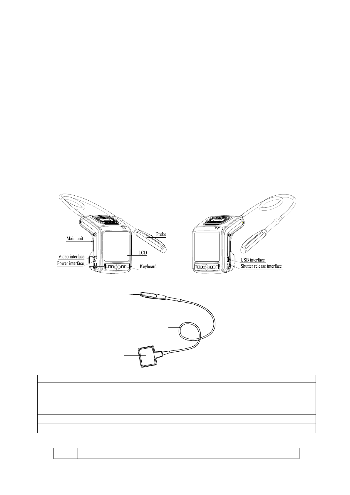
2.2 omponents name
Fig. AGIC 500 main unit sketch map
2.3 Parts of the probe (Take 6.5MHz animal transrectal linear array probe for example)
Fig. Parts name of 6.5 Hz animal transrectal linear array probe
Name Function
(1) Acoustic lens
To convert electric signal to ultrasonic signal based on principle of converse piezoelectric
effect. The ultrasonic signal, after entering the human body, is reflected as echo wave and
converted to electric signal again. The acoustic lens is on the probe surface. Supply ultrasonic
coupling gel to the acoustic lens surface when performing ultrasonic diagnosis.
(2) Cable To connect the probe to the probe connector.
(3) Probe connector To connect the probe to ultrasonic diagnostic system.
2.4 Function keys description
SN. Function keys Real-time mode function Freeze mode function
1
2
3

8
1 ode Selection Text Input
2 Enter Confirm menu
3 ain-menu / Cine loop
4 Freeze/Unfreeze
5 Direction Keys
6 Quit
7 Power switch
hapter Three System onfiguration
3.1 Typical configuration
1. ain unit 1 PC
2. 6.5 Hz animal transrectal linear array probe 1 PC
3. Internal battery 2 PC
4. Charger 1 unit
3.2 Optional parts
1. Probe: 4.0 Hz convex array transrectal probe, 6.5 Hz intra-cavity probe,
5.0 Hz micro-convex probe, 7.5 Hz high frequency linear array probe, 3.5 Hz convex array probe;
2. Video printer: P93W-S
3. ouse
hapter Four Operation ondition
4.1 Power supply
ains voltage: 100-240
±10
ains frequency: 50/60Hz±1Hz
4.2 Operation Environment
Ambient temperature: 10℃-40℃;
Relative humidity: 30%-75% (without condensation);
Atmospheric pressure: 700hPa-1060hPa.
4.3 Storage and Transport
Ambient temperature: -20℃-55℃;
Relative humidity: 30%-93% (without condensation);
Atmospheric pressure: 700hPa-1060hPa.
Attention:
The main voltage is varies with different countries or regions.
Warning:
Avoid using this equipment with high frequency operational equipment, or
danger may occur.

9
hapter Five System Installation and heck
5.1 System placement
Warning:
1. Do not connect the three-wire power supply to unprotected two-
wire socket, or electric
shock may occur.
2. If breakers and fuse of the main power socket are identical to those of the machine, and th
ey
are used to control the current for equipment like life support system, the machine shall not
be connected to such power supply socket as it may cause breaker or fuse to trip and cut off
the power supply to the entire premise in case of malfunction or over current or t
ransient
current generated at power-on with this ultrasonic system.
3.
All plugs of instruments of the system shall be connected into the power socket with
protectively earth on the wall and the socket must meet the requirement of power rating
of
instrument. Multiple portable socket-outlets can not be used for the system.
4. Equipment that connects the signal input part or signal output part
must only connect the
accessories authorized in this manual, and connect the equipment that complies with I
EC
60601-1 standard. When the instrument connects with more than 3 sets of equipment,
it
may cause the danger of the leakage current accumulation.
5.
When system is used around patient, try to avoid the patient touching the system. It can
caused danger of electric shock, if the system is with some defective faults.
Warning:
1. When instrument works abnormally, do stop working, turn off the power and check the
reason, then contacts the EICKEMEYER Company about it.
2. Turn off power and pull out of the plug from socket after each ultrasonic diagnostic
operation.
3. It is forbidden to drag and press the power and probe cables emphatically; r
egularly inspect
whether there is pull-apart and bareness, if there is the phenomena like this, turn off power
supply immediately, stop using it and change it for new one.
4. It is forbidden to load and unload the probe or move the instrument in galvanic to avoid
danger of safety.
5. Pull out of the plug from socket after operation in thunderstorm weather to avoid the
instrument being damaged by lightening.
6. If the temperature changes greatly in short time will cause vapor recovery inside of
instrument, the case may damage the instrument.
7. The
equipment is switched completely only by disconnecting the power supply from the wall
socket.
Attention:
System should be avoided using in following environments:
1. Splash 2. No ventilation
3. Direct sunlight 4. Dramatic temperature change
5. Strong shock 6.Close to heat source
7. Chemical medicines 8. Dust
9. Poisonous gas 10. Corrosive gas
11. Rain 12. Moist
13. Thunderstorm weather 14. Strong electromagnetic field (e.g. MRI)
15. Radiation (e.g. X-ray, CT) 16. Defibrillators or short wave therapy equipment
Danger:
Do not use this equipment where flammable gas (such as anesthetic gas
,
oxygen or hydrogen) or flammable liquid (such as alcohol) are present. F
ailure to do so
may result in explosion.

10
Please carefully read through and fully understand the safety cautions before moving and placing the system.
1. Unpack the instrument case and check the goods for its completeness according to the packing list furnished.
2. Place the instrument on a stable and leveled position.
3. Leave adequate space of 20 centimeters as minimum from rear, left and right side of the instrument.
5.2 Probe installation
5.2.1 Probe connection
Insert the probe connector into the probe socket at the back of the main unit;
5.2.2 Probe disconnection
Turn off the system, and use probe screwdriver to remove the probe with figure’s method and instructions.
Socket screwdriver
According to arrow direction,
gently press socket screwdriver
and remove the probe.
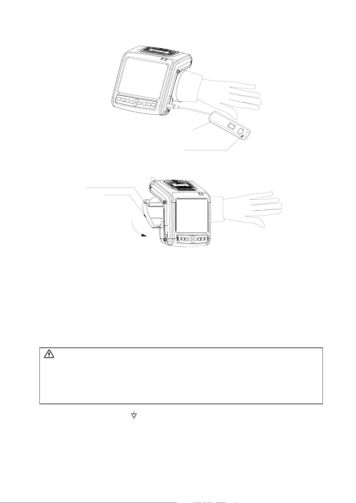
5.3 Shutter release installation
Install shutter release as shown in the figure.
Attention:
Adequate space from rear, left and right side of the machine shall be reserved,
or the machine may malfunction under excessive heat inside the enclosure.
Warning:
Before connecting or using the probe, make sure that the probe, connecting
cable and connector are in normal condition (free of cracks or drop). Use of d
efective
probe may cause electric shock.
Warning:
1. The Eickemeyer ultrasonic probe shall be connected to the dedicated Eickemeyer
ultrasonic
system only. S
elect proper probe model according to the relevant instructions of ultrasonic
diagnostic system.
2. Check the ultrasonic probe and connecting cable after diagnostic operation. Use of
defective probe may cause electric shock.
3. Do not knock or bump the probe, or it may be damaged and cause electric shock.
4. Unauthorized disassembly of the probe shall be prohibited as it may cause electric shock hazard.
Attention:
1. Turn off the ultrasonic system before disconnecting the probe.
Disconnecting the probe
with system power on may damage the system or probe.
2. Before disconnecting the probe, place the cable and probe on a stable and leveled position
so that the probe may not be damaged or injury person by unexpected fall.
3.
Freeze the instrument when instrument is start-up without operation to increase of service life of
probe.
4.
Repeat available machine time should be more than 5 minutes to avoid turn on/off power
supply in short time.
11
Shutter release
In the operation, you can
"freeze" or "unfreeze" images
using shutter release.
5.4 Bind the Arm-Band
Bind the armband with figure’s method and instructions.
1. According to arrow direction, extend your arm
into armband, or disconnect the armband to put
on your arm, the long end through the back ring.
2. According to arrow direction, strain one end of
armband and stick it firmly on the Velcro.
Armband back ring
Arm-Band
5.5 onnect to power
1. Connect to the power adapter
Insert the output plug of adapter into DC power input interface, which is on the left of main unit.
2. Connect to the main power supply
Insert the power plug (jack) furnished with the machine into power input socket of the power adapter, the other end to
the main power supply. The instrument uses three-core power supply. It connects with the protective earth line when
power plug inserts into its socket.
5.6 Video printer installation
1. Connect the equipotential terminal ( ) of the video printer to the earthing;
2. Connect one end of the video connection line to the video printer and the other end to the video output interface on the
left of main unit;
3. Insert one end of power plug (jack) of the video printer to the power input socket of the video printer, the other end to
the power supply socket.
5.7 onnect to the mouse
Connect the mouse to USB interface on the right side of the main unit.
5.8 Probe check before and after operation
Warning:
1. Adapter has no switch. The isolation of the system with the MAINS used to unplug
the
adapter as the intended isolation means.
2. The device should be used only with power adapter provided by Eickemeyer Company.
3. To avoid damaging power adapter or harming people by unexpec
ted fallen, make sure the
power adapter is placed on the leveled desk.

12
Check if there are any exceptionally on the surface of the probe or cable jacket, such as peeling, cracks, bulge, or if the
acoustic lens is reliable, disinfected or cleaned.
5.9 Main unit check before and after operation
5.9.1 Inspection before start-up
Check the following items before starting the machine:
1. The temperature, humidity and atmospheric pressure shall meet the requirements of operation condition.
2. No condensation occurs.
3. No distortion, damage or contamination on system and peripheral. Clean the parts as specified in relevant sections, if the
contaminant is present.
4. Examine the control panel, LCD screen and enclosure to ensure they are in good working condition and free of abnormity
(such as cracks and loosened screws).
5. No damage on power cable, and hard up on its connection.
6. Check probe and its connections to ensure they are free of abnormity (such as scuffing, drop-off or contamination). If the
contaminant is present, clean, disinfect the contaminated objects as specified in relevant sections.
7. No barriers around the intake of equipment.
8. See to it that probe has been cleaned, disinfected and sterilized; else dispose it as specified in relevant sections.
9. Check all the ports of the machine for possible damage or blockage.
10. Clean the field and environment.
5.9.2 Inspection after start-up
Check the following items after starting the machine:
1. No abnormal voice, strange smell and overheating appear.
2. Check the machine to ensure a normal start-up: The power indication light is on and startup picture is shown on the
screen. The machine will be then automatically set in B mode.
3. Check the acoustic lens for abnormal heat when the probe is in use. This can be done by hand touching the probe to feel
the temperature of the lens.
4. Check the image to ensure trouble-free display (no excessive noise or flicker).
5. Check the control panel to ensure normal operation condition.
6. Check the instrument to ensure that the phenomenon of local high temperature will not appear.
5.10 System reset
In case of abnormal screen display or no-working for system operation, try to restart the system by turning on/off the main
unit power.
hapter Six Functional Operation
6.1 Startup and Shutdown
In shutdown status, press key, machine starts up, power indicator lights.
In startup status, press key, machine shuts down, power indicator goes out. Please note that when shut down the
machine, the time of pressing key is a rather long than normal pressing key.
6.2 System Functions Setting
6.2.1 Time Setting
1. Press key to enter main-menu and press direction keys to move cursor to “Preset”;
2. Press direction keys to enter setting interface;
Attention:
If the overheat acoustic lens is placed on the patient’s skin, heat injury may occur.
Attention
: Thoroughly clean the coupling
gel on the probe surface each time after
ultrasonic operation, or the coupling gel may become hardened on the acoustic lens of
the
probe, deteriorating quality of image.
13
3. Press direction keys to select inutes, Hours, Day, onth and Year;
4. When setting minutes, hours, day, month and year, press direction key to increase value or press direction key to
decrease value;
5. Press key to confirm the time setting and quit setting interface.
6.2.2 TV Mode Setting
1. Press key to enter main-menu and press direction keys to move cursor to “Preset”;
2. Press direction keys to enter setting interface;
3. Press direction keys to move symbol “<” to point to “TV mode”;
4. Press direction keys to realize TV mode conversion between PAL and NTSC;
5. Press key to quit setting interface.
6.2.3 Energy Saving Setting
1. Press key to enter main-menu and press direction keys to move cursor to “Preset”;
2. Press direction keys to enter setting interface;
3. Press direction keys to move symbol “<” to point to “Sleep”;
4. Press direction keys to select energy saving time among 1~99 minutes or select “Off”;
5. Press key to quit setting interface.
6.2.4 haracters Brightness Setting
1. Press key to enter main-menu and press direction keys to move cursor to “Preset”;
2. Press direction keys to enter setting interface;
3. Press direction keys to move symbol “<” to point to “Font Bright”;
4. Press direction keys to select characters brightness among 160, 192, 224 and 255;
5. Press key to quit setting interface.
6.2.5 Hospital Name Setting
1. Press key to enter main-menu and press direction keys to move cursor to “Preset”;
2. Press direction keys to enter setting interface;
3. Press direction keys to move symbol “<” to point to “Hospital”;
4. Press key, the cursor is located above “NA E”; at the same time characters input menu will be shown at the bottom
of the screen:
Caps 0 1 2 3 4 5 6 7 8 9 a b c d e f g h
Shift i j k l m n o p q r s t u v w x y z
Press direction keys or operate mouse to move cursor to point to Caps, and then press key or click left mouse to
achieve capital and small letter conversion; If the cursor point to Shift, press key or click left mouse again to achieve the
conversion between the letter and punctuation;
5. Press direction keys to choose “numbers” or “characters” and press key to confirm; Or operate mouse to click
“numbers” or “characters” to input;
6. If need modify the content, press key to quit the character input menu, press direction keys to delete input
content; press key again to retype;
7. Press key to save this setting and quit setting interface.
6.2.6 Key Sound Setting
1. Press key to enter main-menu and press direction keys to move cursor to “Preset”;
2. Press direction keys to enter setting interface;
3. Press direction keys to move symbol “<” to point to “Key Sound”;
4. Press direction keys to select between “On” and “Off”;
5. Press key to quit setting interface.

14
6.2.7 ompression urve Setting
1. Press key to enter main-menu and press direction keys to move cursor to “Preset”;
2. Press direction keys to enter setting interface;
3. Press direction keys to move symbol “<” to point to “Compression Curve”;
4. Press direction keys to select compression curve among “00” –“15”, recommend use 04;
5. Press key to quit setting interface.
6.2.8 hinese-English Setting
1. Press key to enter main-menu and press direction keys to move cursor to “Preset”;
2. Press direction keys to enter setting interface;
3. Press key to switch between Chinese and English;
4. Press key to quit setting interface.
6.3 Brightness and ontrast Adjustment
In the startup default status, press freeze key to unfreeze, press key to quit the current using status, the adjustment bars
of brightness and contrast will be displayed on the screen by pressing direction keys , adjust them according to actual
need. Press direction key to increase brightness and contrast, direction key to decrease them; press direction
keys to select brightness or contrast adjustment.
Note: If direction keys cannot be adjusted when adjust brightness in normal operation mode, must be exit current
operating condition of direction keys.
6.4 Mode selection
In real-time mode, press key repeatedly to realize mode switching of B, B/B, 4B, B/ and .
6.4.1 B Mode
B mode is a basic operation mode after startup and a single-framed B mode image is displayed.
6.4.2 B/B Mode
1. In real-time mode, press key to enter B/B mode.
2. B/B image switch. Press key to enter main-menu and press direction keys to move the cursor to “B/B ode”
and then press direction keys to switch image display. Or right click mouse to switch image display, the selected
image is activated and the other one is frozen.
3. In real-time mode, press key to exit B/B mode.
6.4.3 4B Mode
1. In real-time mode, press key to enter 4B mode.
2. 4B image switch. Press key to enter main-menu and press direction keys to move the cursor to “4B ode”,
then press direction keys to switch display among four images; Or right click mouse to switch display among four
images, the selected image is activated and the other three are frozen.
3. In real-time mode, press key to exit 4B mode.
6.4.4 B/M Mode
1. In real-time mode, press key to enter B/ mode.
2. Change of scan mode. Press key to enter main-menu and press direction keys to move cursor to “ ode”
and then press direction keys to change the ultra-scan mode. Or right click mouse to realize the change of scan
mode.
3. ove sample line. Press key to quit the current using status for direction keys. Press direction keys to move sample
line.
4. In real-time mode, press key to exit B/ mode.
6.4.5 M Mode
1. In real-time mode, press key to enter mode.
2. Change of -scan mode: Press key to enter main-menu and press direction keys to move cursor to “ ode”
and then press direction keys to change the ultra-scan mode. Or right click mouse to realize the change of scan

15
mode.
3. Change of speed: Press key to enter main-menu and press direction keys to move cursor to “ Speed” and
then press direction keys to select the eight kinds of scan speed. Or left click mouse to switch speeds.
4. In real-time mode, press key to exit mode.
6.5 Image Gain and Dynamic Range Adjustment
6.5.1 Total Gain Adjustment
In real-time mode, press key to enter main-menu and press direction keys to move cursor to “Gain: ” in the
display area. Press direction key to increase image total gain and direction key to reduce total gain so as to control the
total gain of the entire image.
6.5.2 Near Field Gain Adjustment
In real-time mode, press key to enter main-menu and press direction keys to move cursor to “Near: ” in the
display area. Press direction key to increase near field gain and direction key to reduce near field gain so as to control the
gain in near field region.
6.5.3 Far Field Gain Adjustment
In real-time mode, press key to enter main-menu and press direction keys to move cursor to “Far: ” in the display
area. Press direction key to increase far field gain and direction key to reduce far field gain so as to control the gain in far
field region.
6.5.4 Dynamic Range Adjustment
In real-time mode, press key to enter main-menu and press direction keys to move cursor to “Dyn: ” in the display
area. Press direction key to increase the value of dynamic range and direction key to decrease the value of dynamic range
so as to control the dynamic range of the entire image.
6.6 Selection of Magnification, Frequency, Frame orrelation, Image Post-process, Edge Enhancement, Focus Number, Local
Zoom and Depth Heighten
6.6.1 Magnification Selection
In real-time mode, press key to enter main-menu and move cursor to “Zoom” and then press direction keys to
choose eight kinds of magnification.
6.6.2 Frequency Selection
In real-time mode, press key to enter main-menu and press direction keys to move cursor to “Freq.” in the
display area. Press direction keys to realize frequency conversion.
6.6.3 Frame orrelation Selection
In real-time mode, press key to enter main-menu and press direction keys to move cursor to “Avg” in the
display area. Press direction keys to realize four levels of frame correlation.
6.6.4 Image Post-process Selection
In real-time mode, press key to enter main-menu and press direction keys to move cursor to “IP” in the display
area and then press direction keys to obtain corrected image. System default is 2.
6.6.5 Edge Enhancement Selection
In real-time mode, press key to enter main-menu and press direction keys to move cursor to “Edge” in the display
area and then press direction keys to gain four levels of sharpened images. System default is 0.
6.6.6 Focus Selection and ontrol
In real-time mode and in B, B/B or 4B mode, press key to enter main-menu and move cursor to “F. Num” and then
press direction keys to choose from the four focus modes of stage 1(Full process dynamic focus), 2, 3 and 4.
In real-time mode and in B, B/B, 4B, B/ or mode, press key to quit menu mode, press direction keys again to
move the single focus up and down; focus is intelligent in the status of stage 2, 3 or 4, the focal position and focal length can not
be changed in this time.
Note: In B/M or M mode, only allowed choose single focus mode.
6.6.7 Local Zoom and Local Additive olor

16
In real time B mode, press key to enter main-menu and press direction keys to move cursor to “Local Zoom” in
the display area and then press direction keys , a box appears. Press direction keys or operate mouse to move the box to
the position to be enlarged, the selected image be enlarged; Press key to quit local zoom status.
In the color display, the selected image which by above mentioned operation will be enlarged and added color.
6.6.8 Depth Selection and Depth Enhancement
In real-time mode, press key to enter main-menu and press direction keys to move cursor to “Depth” in the
display area and then press direction keys to select depth, press key to quit depth selection.
Note: There is no depth selection function when main unit matching probe which its nominal frequency greater than or
equal to 6.5MHz.
In real-time mode, press key to enter main-menu and press direction keys to move cursor to “Upgrade” in the
display area and then press direction keys , “ ” appears on the screen. Press direction keys or operate mouse to move
image up/down or left/right so as to observe the images of different depth and width. Press key to quit depth heighten/pan
status.
6.7 Image Horizontal/Vertical Reverse, Negative, olor Selection, Scan Range and Puncture Line
6.7.1 Image Left/right Reverse
In real-time mode and in B, B/B, 4B or B/ mode, press key to enter main-menu and press direction keys to
move cursor to “H Rev” and then press direction keys to realize image horizontal reverse. Or left click mouse also to
realize image horizontal reverse. The image horizontal reverse is the change of probe scanning direction. The probe scanning
direction is indicated by the arrow on the upper left area of the image.
6.7.2 Image Up/down Reverse
In real-time mode, press key to enter main-menu and press direction keys to move cursor to “V Rev” and then
press direction keys to realize image vertical reverse.
6.7.3 Image Negative
In real-time mode, press key to enter main-menu and press direction keys to move cursor to “Image POS” and
then press direction keys to realize negative function.
6.7.4 olor Selection
In real-time mode, press key to enter main-menu and press direction keys to move cursor to “COLOR:” in the
display area and then press direction keys to realize color conversion of eight colors (including one kind of black and
white).
6.7.5 Scan Range (Angle/Width hange)
In real-time B mode, press key to enter main-menu and press direction keys to move cursor to “Angle” and then
press direction keys to choose angle/width.(convex array for scanning angle and linear array for scanning width).
6.7.6 Puncture guide and lithotripsy positioning line
Puncture guide line: In real-time B mode, press key to enter main-menu and press direction keys to move cursor
to “Puncture” and then press direction keys to choose line 1, press key to confirm, two puncture guide lines appear
on the screen, press direction keys to change the angle of the first puncture guide line, press direction keys to
change the start position of the first puncture guide line. Press key again to enter main-menu and press direction
keys to move cursor to “Puncture” and then press direction keys to choose line 2, press key to confirm, press
direction keys to change the angle of the second puncture guide line, press direction keys to change the start
position of the second puncture guide line. Press key to quit the puncture guide status.
Lithotripsy positioning line: In real-time B mode, press key to enter main-menu and press direction keys to move
cursor to “Puncture:” and then press direction keys to choose line 3, press key to confirm, lithotripsy positioning line
appears on the screen. Repeatedly press key to realize the switch of lithotripsy positioning line between show and hide.
Press key to quit.
6.8 Image Freeze/Unfreeze
In real-time mode, press key or middle mouse key to freeze the image; in frozen status, press key or middle mouse

17
key to unfreeze the image.
6.9 Body Mark and Probe Mark
This product contains 22 body marks that are divided into two pages when display. The operation steps are as follows:
1. In frozen status, press key to enter main-menu and press direction keys to move cursor to “Body mark”,
press key, body marks will be showed in the image area, press direction keys to change pages;
2. Press direction keys to move to the position of desired body mark, press key to confirm the selected body mark;
3. Press direction keys or operate mouse to change the probe mark position; press key to change probe mark direction;
4. Press key to quit body mark and probe mark status;
5. Press key to quit froze and body mark status.
6.10 Image files storage and recall
6.10.1 Save image file
Storage to main unit
1. Freeze the image;
2. Press key, a “Save” prompt appears on lower right corner of the screen;
3. Press direction keys to select the image code need to be saved in the “LOCAL”, such as choose “003”;
4. Press key to appear “Wait” prompt. After the prompt disappear, the current image is saved in the frame for coded
“003”. The saved image code is preceded with asterisk “*”;
5. Press key to quit saving status and press key to return to real-time status.
Storage to U disk
1. Plug U disk;
2. Freeze the image;
3. Press key, a “Save” prompt appears on lower right corner of the screen;
4. Press direction keys to select the image code need to be saved in the U disk, such as choose “004”;
5. Press key to appear “Wait” prompt. After the prompt disappear, the current image is saved in the frame for coded
“004”. The current image is saved under the specified folder in the U disk; the folder name is patient number (ID), which is
made up of underline, letters or numbers, without spaces; file name is the selected saving code. If user did not enter the
number (ID), the folder name defaults to “USER”;
6. Press key to quit saving status and press key to return to real-time mode.
Explanation:
1. Each number (ID) corresponds to a folder, the largest storage for each folder is 100 images.
2. Press key, can select “LO AL” or “U Disk”.
6.10.2 Open image file
Open image in the main unit
1. Freeze the image;
2. Continuously press key twice, a “Read” prompt appears on lower right corner of the screen;
3. Press direction keys to select the image code need to be read out in the “LOCAL”, such as choose “003*”;
4. Press key to appear “Wait” prompt. After the prompt disappear, the image stored in frame “003*” is read out;
5. Press key to quit reading status and press key to return to real-time status.
Open image in the U disk
1. Plug U disk;
2. Freeze the image;
3. Continuously press key twice, a “Read” prompt appears on lower right corner of the screen;
4. Press direction keys to select the image code need to be read out in the U disk, such as choose “004*”;
5. Press key to appear “Wait” prompt. After the prompt disappear, the image stored in frame “004*” is read out;
6. Press key to quit reading status and press key to return to real-time status.

18
Explanation:
1. When reading images, it must choose the image code with “*”. The stored and read out images are all black and white
images.
2. In the status for saving or reading images, press key, can delete the image with “*” mark in main unit or in the U
disk.
6.11 Single dump and mass dump
6.11.1 Single dump
From main unit to U disk
1. Read out the image in the main unit, “Img” with highlight status is displayed on lower right corner of the screen;
2. Press key, a “Dump” prompt appears on lower right corner of the screen;
3. Press direction keys to select the image saving code in the U disk, such as choose “005”;
4. Press key, “Dump” prompt disappears, until the “Dump” re-appears, the current image can be dumped in the frame for
coded “005”. The dumped image code is preceded with asterisk “*”;
5. Press key to quit dumping status and press key to return to real-time status.
From U disk to main unit
1. Read out the image in the U disk, “Img” with highlight status is displayed on lower right corner of the screen;
2. Press key, a “Dump” prompt appears on lower right corner of the screen;
3. Press direction keys to select the image saving code in the “LOCAL”, such as choose “006”;
4. Press key, “Dump” prompt disappears, until the “Dump” re-appears, the current image can be dumped in the frame for
coded “006”. The dumped image code is preceded with asterisk “*”;
5. Press key to quit dumping status and press key to return to real-time status.
6.11.2 Mass dump
From main unit to U disk
1. Freeze the image, continuously press cine loop key until enter “PAUSE” status;
2. Press key, “LOCAL -> U Disk ass Dump?” prompt display at the bottom of the screen;
3. Press key, “Dumping” prompt appears, images are mass dumped under the “DU P” folder in the U disk, and the
number behind “PAUSE” character is the number of folder name of mass dumping. After finishing mass dumping, return
to “PAUSE” status;
4. Press key to quit mass dumping status and press key to return to real-time status.
From U disk to main unit
1. Plug U disk;
2. Freeze the image, continuously press cine loop key until enter “PAUSE” status;
3. Press key twice, “U Disk -> LOCAL ass Dump?” prompt display at the bottom of the screen;
4. Press key, “Dumping” prompt appears, the number behind “PAUSE” character is the number of folder name of mass
dumping. After finishing mass dumping, return to “PAUSE” status;
5. Press key to quit mass dumping status and press key to return to real-time status.
Explanation: Mass dump, which is dump images from main unit to “DUMP” folder in the U disk; can also dump the images
under the “DUMP” folder in the U disk to main unit.
6.12 ine loop
In real-time mode, the system is always saving the scanned image. The playback images are for a period time images
before freeze.
Freeze the image, continuously press key three times to enter the automatic playback status; Press key to enter
pause status when playing back; Press direction keys or operate mouse to view images frame by frame in pause status;
Continuously press key three times again to return to automatic playback status. In the process of saving and playback,
relevant data of image frames saved and played are shown on the lower right corner of the screen.
Press key to return to frozen status.
19
Press key unfreeze and quit playback status.
Note: If the images appear abnormal, that is without enough storage time and the images have not been stored full.
6.13 Text Input
Operation steps:
1. Freeze image;
2. Press key, the cursor is located behind name;
3. Press key again or right click mouse, at the same time characters input menu will be shown at the bottom of the
screen:
Caps 0 1 2 3 4 5 6 7 8 9 a b c d e f g h
Shift i j k l m n o p q r s t u v w x y z
Press direction keys or operate mouse to move cursor to point to Caps, and then press key or left click mouse to
achieve capital and small letter conversion; If the cursor point to Shift, press key or left click mouse again to achieve
the conversion between the letter and punctuation;
4. Press direction keys to choose “numbers” or “characters” and press key to confirm; Or operate mouse to click
“numbers” or “characters” to input;
5. After inputting name, press key and then press direction key to move cursor to “ID” and press key again to
input according to Step 4, the number (ID) only be made up of numbers, letters or underlines;;
6. After inputting ID, press key and press direction keys to move cursor to image area and press key again to input
according to Step 4;
7. If need modify the content, continuously press key twice to quit annotation status, press direction keys to
select “Clear”, at last press key to clear all noted marks and retype;
8. Press key to quit.
6.14 ase report processing center V3.1 software (optional)
6.14.1 Function Introduction
1. Connect computer with USB interface of main unit, ultrasonic images transmit to PC and realize images mass memory.
2. Support five types case report template edit and print.
6.14.2 Use Instruction
1. Follow the "USB Installation Instruction V3.1" of CD to install the "Case Report Processing Center V3.1" software.
2. Insert USB cable into "USB interface" of main unit, and then switch on the power of main unit.
3. Connect the other end of USB cable to "USB Interface" of computer.
4. Open the "ImageUsb.exe" file in the Case Report Processing Center V3.1, that is double click the logo , and
click , then click "Start", the current displaying image transmitted to PC.
5. Click "Save" and then input the file name, so the image saved to PC.
6. Press the button to exit the Case Report Processing Center V3.1.
7. A detailed use instruction sees also the "Use Instruction V3.1" in the CD.

20
hapter Seven General Measurement
7.1 Distance Measurement
1. In B, B/B or B/ mode, choose desired image and freeze it, the cursor is located in the “ easure” position of display
area;
2. Press key, the measurement methods are showed in the lower left of the screen, press direction keys to
choose “Distance”, press key again, the cursor will show “+”; or click left mouse, the cursor will show “+”;
3. Press direction keys or operate mouse to move the “+” mark to desired position, press key or click left mouse to
set the “+” mark position as the start of the measurement;
4. Press direction keys or operate mouse to move the“+” mark to the end of the measurement. A lighted dotted line
appears between the start and the end as the dashed locus of the measurement. The measured value is automatically
displayed at the built-in mark“+: ----mm” on the right side of the screen;
5. Press key or click left mouse repeatedly to exchange the start and end of the measurement;
6. Press key or click right mouse to finish the first measurement;
7. Repeat the steps 3~6 to complete the multi-group data measurement;
8. Continuously press key twice to quit the measurement status;
9. Press direction keys to choose “Clear” or synchronously click the left and right key of mouse to clear all marks
and data;
10. Press key or click the middle mouse to unfreeze, clear all marks and data and quit the measurement status.
7.2 ircumference/Area/Volume Measurement
ircumference/area measurement with trace method
1. In B, B/B, B/ mode, choose desired image and freeze it, the cursor is located in the “ easure” position of display
area;
2. Press key, the measurement methods are showed in the lower left of the screen, press direction keys to
choose “Trace”, press key again, the cursor will show “+”; or click left mouse, the cursor will show “+”;
3. Press direction keys or operate mouse to move the “+” mark to desired position, press key or click left mouse to
set the “+” mark position as the start of the measurement; or click right mouse to set the “+” mark position as the start
of the measurement;
4. Press direction keys or operate mouse to move the“+” mark to the end of the measurement. A locus appears in the
direction of operation between the two measurement marks. The measured circumference value is displayed
automatically at the built-in mark “C: 00000mm” on the right part of the screen. Press key or click right mouse to
display at the built-in mark “A: 00000mm
2
” the value of the measured area formed by measurement line enclosure;
5. Press key, the measurement methods are showed in the lower left of the screen, continue to choose “Trace” to
measure;
6. Repeat steps 3, 4 to complete the multi-group data measurement;
7. Continuously press key twice to quit the measurement status;
8. Press direction keys to choose “Clear” or synchronously click the left and right key of mouse to clear all marks
and data;
9. Press key or click the middle mouse to unfreeze, clear all marks and data and quit the measurement status.
ircumference/area/volume measurement with ellipse method
1. In B, B/B, B/ mode, choose desired image and freeze it, the cursor is located in the “ easure” position of display
area;
2. Press key, the measurement methods are showed in the lower left of the screen, press direction keys to
choose “Ellipse”, press key again, the cursor will show “+”; or click left mouse, the cursor will show “+”;
3. Press direction keys or operate mouse to move the “+” mark to desired position, press key or click left mouse to
set the “+” mark position as the start of the measurement;
4. Press direction keys or operate mouse to move the“+” mark to the end of the measurement, at the same time the
Table of contents
Other Eickemeyer Pet Care Product manuals


