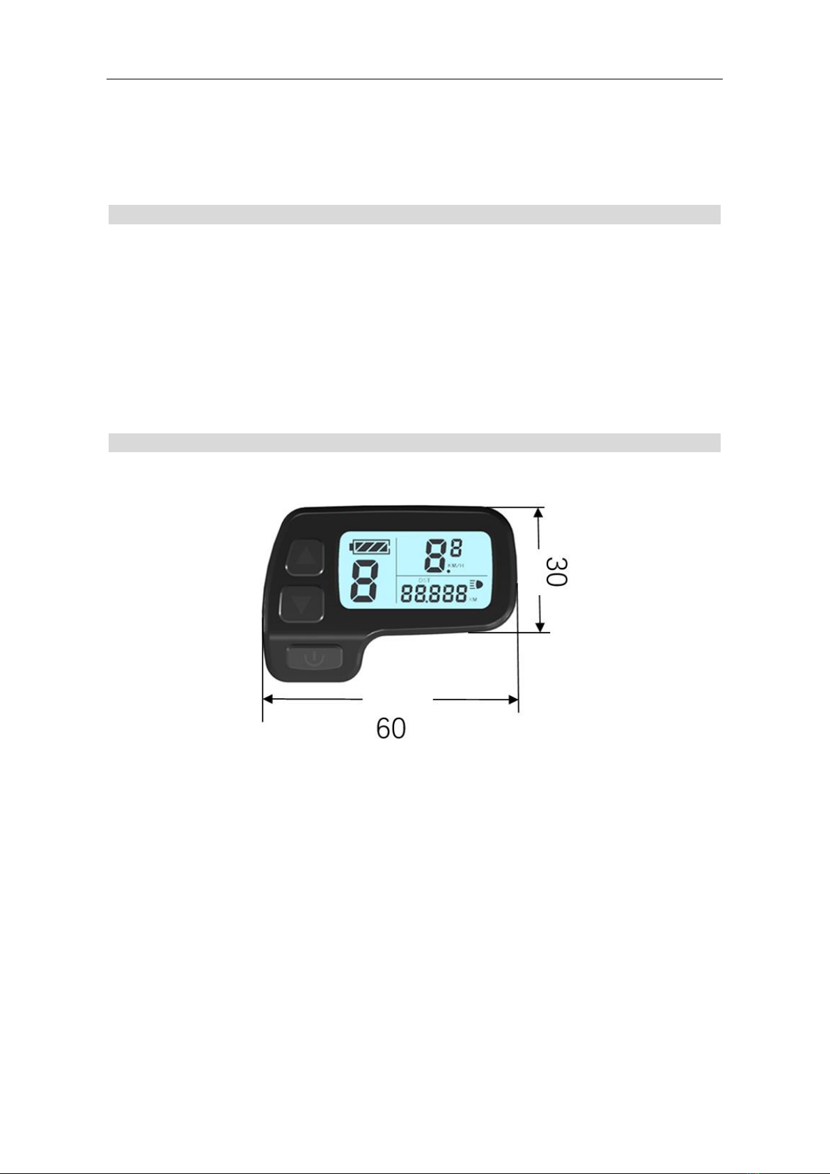
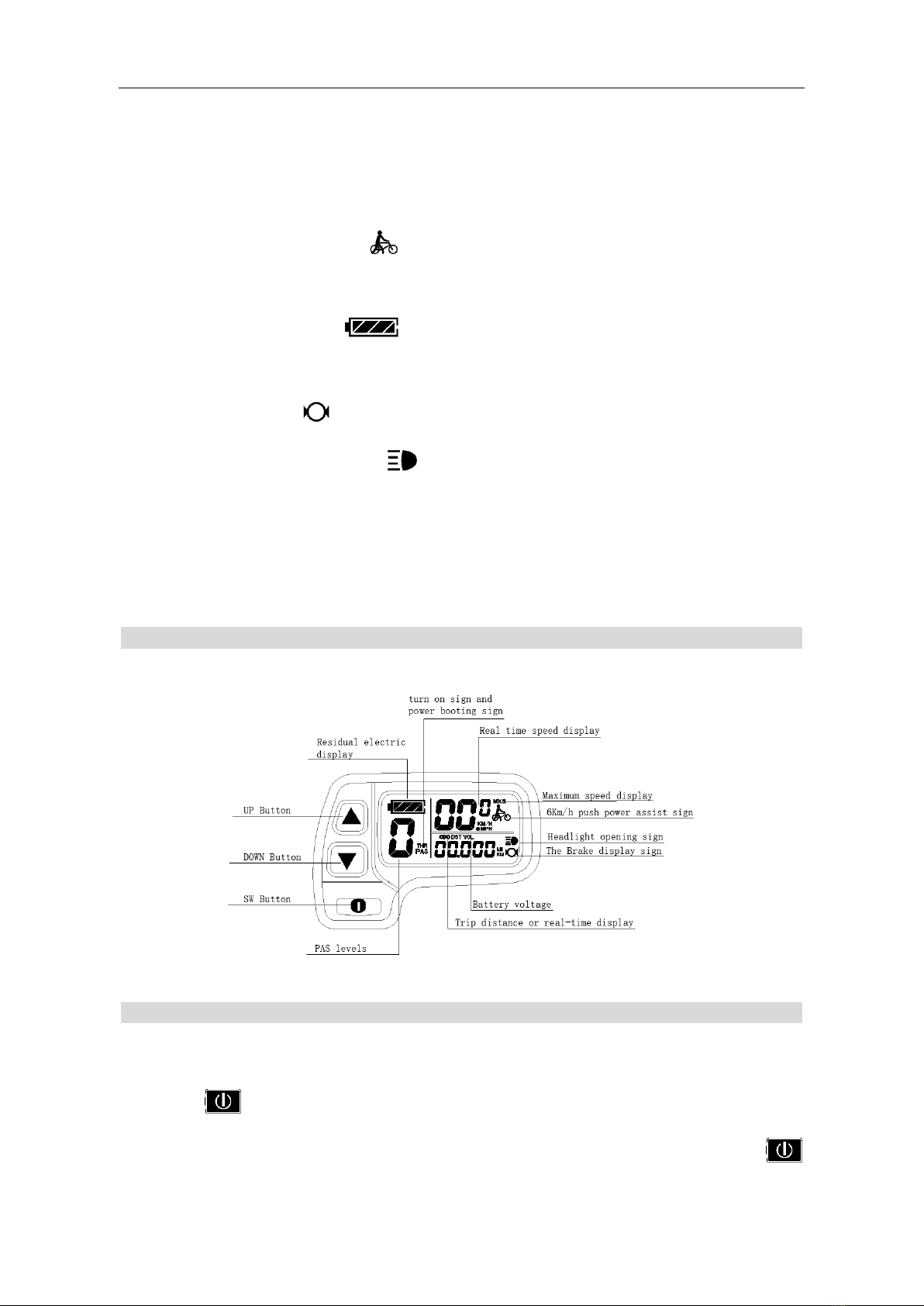
ELECTRIC BICYCLE METER KT—LCD11 Product User Manual
- 2 -
Maximum Trip Speed………………………………………………………….......... 14
Wheel Diameter…………………………………………………………………..…. 14
Metric and Imperial Units…………………………………………………………... 15
Exit General Project Setting……………………………………………………….... 16
P Parameter Setting……………………………………………………………….…….... 16
P1 Motor Characteristic Parameter Setting ............................................................... 16
P2 Wheel Speed Pulse Signal Setting ....................................................................... 17
P3 Power Assist Control Mode Setting ...................................................................... 17
P4 Throttle Startup Setting ..................................................................................... 18
P5 Power Monitoring Setting ..................................................................................19
C Parameter Setting ............................................................................................................ 19
C1 Power-assist Sensor and Parameter Selection Setting ......................................... 19
C2 Motor Phase Classification Coding Setting .......................................................... 20
C3 Power-assist Ratio Gear Initialization Setting ..................................................... 21
C4 Throttle Function Setting .................................................................................. 22
C5 Controller Maximum Current Adjustment Setting ............................................... 23
C6 Backlight Brightness Adjustment Setting ............................................................. 24
C7 Cruise Function Setting ........................................................................................ 25
C8 Not Identified....................................................................................................... 25
C9 Power-on Password Setting .................................................................................. 26
C10 Automatic Restore Default Setting ..................................................................... 27
C11 Attribute Selection Setting .................................................................................. 27
C12 Controller Minimum Voltage Adjustment Setting ............................................. 28
C13 ABS brakes of the controller and parameters of anti-charge control Setting ......30
C14 Power-assist Tuning Parameters Setting .............................................................31
C15 Push-assist Speed Parameters Setting...................................................................31
Exit Parameter Setting................................................................................................. 32
L Parameter Setting ............................................................................................................ 32
L1 Parameters Setting .................................................................................................32
L2 Parameters Setting ...........................................................................................33