Ejoin Charger 22kW User manual

ejoin Charger 22kW
ejoin Charger 7kW
ejoin Wallbox 22kW
ejoin Wallbox 7kW
Manual
Copyright © 2019 ejoin. s.r.o. - All rights reserved
1/24

About the Document
Version: 1.0
Release Date: 05/2019
Symbols used in this document for easy reference
iThis symbol indicates the author’s notes for informative purposes. It is
recommended to read the information thereof.
!This symbol indicates critical information required for the safety and operation of
the charging station. It is essential to read and observe the information thereof.
0This symbol indicates critical safety-related information when working with
hazardous equipment that pose a risk to human health. It is essential to read and
observe the information thereof.
Copyright
This document and information contained herein are the intellectual property of ejoin s.r.o.
(hereinafter the ‘Author’), based in the Slovak Republic and subject to copyright laws. The Author
reserves all right to reproduce and distribute this document. No part of it may be reproduced,
copied, or processed in any way without the express permission of the Author.
2/24

Contact Information
Address: ejoin s.r.o., Hviezdoslavova 1168, 018 63 Ladce, Slovakia
E-mail: [email protected]
Internet: http://www.ejoin.eu
Info Line: +421,424,111,111
Current contact information and contact points for other EU countries are available on the Author’s
website (see above).
3/24

Introductory Information
Congratulations on your purchase of the charging station. We believe that its use will bring you a lot
of positive experience with charging your electric car. During the development of the station we
made sure that its operation was as simple and safe as required by the applicable EU- and world-
wide standards and legislations. It is now up to you to familiarize yourself with this Manual, which
will provide you with all the information you need to know before the installation and operation of
the charging station. This will prevent a possible failure or damage to the charging station, damage
to health or property, and the resulting disappointment with the product.
i
!
Read this document carefully. If any information contained herein is not clear
enough, or if you have any inquiries, please contact us using the contact
information given in this document in the Contact section.
Product Description
iThis device is a charging station designed to charge on-board batteries of AC-
enabled electric vehicles. It is intended for individual use.
What Do I Need to Know Before Installing the Charging Station?
!
Read this Manual before installing and using the charging station for the first time.
Carefully consider all the circumstances and perform the steps given in this
Manual. Understand the operating conditions and features of the charging station,
and make sure that they are observed during installation and use.
The manufacturer disclaims any and all responsibility for damages to the
charging station, health, and other property that may result from a failure to
comply with this Manual, best practices, and operating conditions.
4/24
Who Can Install the Charging Station?
!
0
Since the charging station is an electrical device that operates under voltages
hazardous to human health, and whose top cover has to be removed during
installation exposing the live parts inside, it is essential that a qualified electrical
engineer performs the installation with a valid professional license in electrical
engineering. As given in the Introduction, unauthorized installation may lead to a
failure of the charging station and/or cause a personal injury or damage to the
charging station or other property.
When It Is Allowed to Install the Charging Station?
!
0
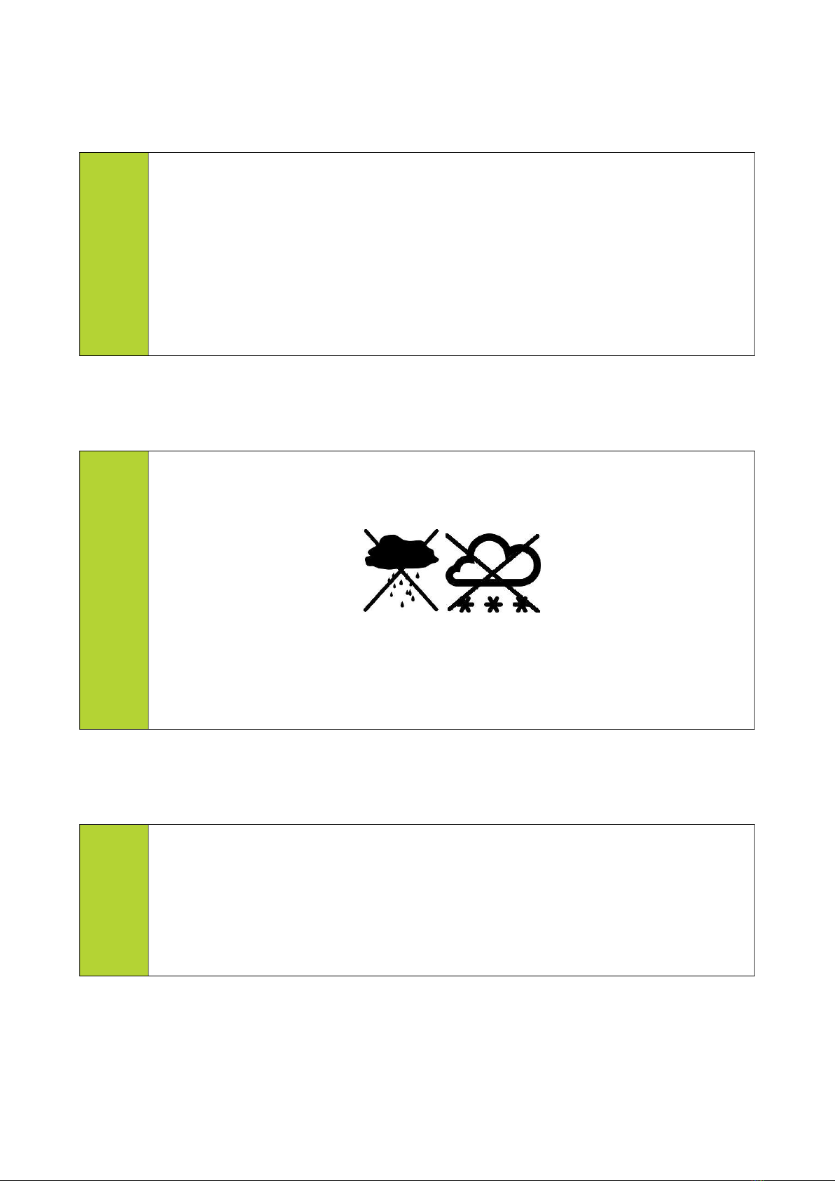
If you plan to install the charging station in an outdoor environment, do not do so
during snowy, rainy, or humid weather. Otherwise, water may enter the equipment
during installation, which can have fatal consequences.
The charging station has to be acclimatized to the outdoor temperature; leave
it outside for at least 1.5 hours before opening (due to condensation of air
humidity).
Where Can the Charging Station Be Installed?
i
!
The charging station is equally fit for indoor and outdoor environments. Although
its cabinet is made of non-combustible metallic material and is sealed hermetically,
it is recommended to mount it on a non-combustible pad away from any
combustible materials (wood, etc.) and heat sources.
5/24
Pedestal Charger
6/24
Wallbox Charger
What Are the Power Supply Requirements?
i
!
0
The charging station can be plugged to a three-phase power supply unit of 3x400V/
230V/50Hz only via 3P+N+PE connection, which means that in addition to the L1,
L2, and L3 three-phase wiring, a neutral (N) and protective earthing (PE) conductor
must be supplied separately. It is strictly forbidden to omit the PE conductor or
ground it at the charging station through the N conductor.
In order to minimize losses on the supply line, it is recommended to use a cable
with the shortest possible length. It is recommended to use a fixed supply cable of
the CYKY-J 3x6 type (3-core conductor with a full core and cross-section of 6mm²
for single-phase charging stations) or 5x6 type (5-core conductor with a full core
and cross section of 6mm² for three-phase charging stations) or CYKY-J 3x10 /
5x10 type (core cross-section of 10mm²); wiring with this cross-section are
particularly suitable for longer cables.
If your charging station is not equipped with a circuit breaker, your
installation must include a suitable breaker element with a rated current of
32A and breaking capacity matching the properties of your power system.
If your charging station is equipped with a circuit breaker, it is required to
check that its breaking capacity is sufficient for your network. Otherwise, it is
required to install an additional upstream circuit breaker in the charging
station that matches the properties of your power system.
It is recommended to equip your power system by a surge protector to meet the
CAT III requirements of in line with the IEC 60664 Standard.
7/24
Figure

What Equipment Is Required to Install the Charger?
i
Mandatory Equipment
PH2 Screwdriver (for screwing the charger’s lid)
Screwdriver flat 4.0 (for screwing lead wires onto the terminal board)
Screwdriver long, type depending on the bolt used
Miscellaneous Equipment
Screwdriver flat 3.0 (for screwing signal wires onto the terminal block)
Metering instrument to make a safe detection of AC supply voltage of
400V/230V/50Hz.
Drill with a matching attachment (for wallbox installations to make holes into a
wall - to insert dowels)
Stripping pliers (stripping the power cord before connecting it to the charging
station terminal board)
Note for owners of the Pedestal Charger:
The list of the mandatory equipment does not include the tools needed to install the pedestal. This
depends on the user-selected means of anchorage and grounding.
What Consumables Are Needed to Install the Charger?
i
Four pieces of fastening screws with suitable length and diameter
(recommended type - 4x50mm screw, for wallbox only) - needed to attach the
charger cabinet to the anchors
Four pieces of anchors (dowels, for wallbox only) with dimensions matching the
type of the screw used according to the previous paragraph and type of anchor
matching the surface material to hold the Wallbox Charger.
Miscellaneous material supplied as part of the charging station.
Note for owners of the Pedestal Charger:
The list of consumables does not include the materials needed to install the pedestal. This depends
on the user-selected means of anchorage and grounding.
8/24

When Can I Start Using the Charger?
!
0
The charger can be used once all the installation steps have been performed
successfully; however, please note that before the final commencement, it is
required to obtain an authorization that the system is fit for purpose from an
electrical engineer with a valid license (Electrical Inspector).
9/24
Charger Station Assembly
Warning and General Information
!
0
Before installation, make sure that the power cord is not live. In addition,
prevent other people from handling the switchgear of the upstream power
cord to avoid accidental start-up.
Remove any and all people from the area that could compromise the safety
of anyone involved, such as kids, people with disabilities, the elderly, people
suffering from mental disorders that are at a risk of unpredictable behaviour,
people under the influence of alcohol, psychotropic substances, or narcotic
drugs, and the like.
Remove any and all items that could compromise the safety of anyone
involved, such as road obstacles, debris and other objects laying around,
containers with flammable liquids, potential
sources of fire, and the like.
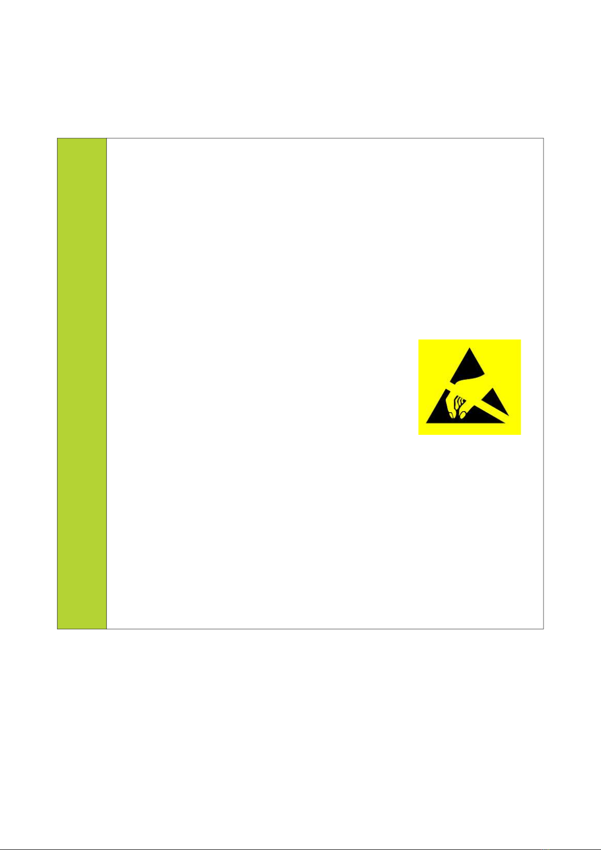
The charger contains electrostatic discharge
sensitive devices (ESD). It is advisable to install the
charger while wearing antistatic clothing and shoes
(linen, cloth, leather) and avoid rubber soles and
synthetic materials (polyester, nylon, etc.). Avoid
unnecessary contact with the printed circuit board of the control system by
hand or a tool. Before and during installation, it is recommended to
continuously touch the grounded metal object to discharge the accumulated
electrical charge, taking care not to touch another metal live part by another
part of the body.
If you have brought the charger from a location with a different ambient
temperature, leave the unit for a period of time to adjust (see ‘Introductory
Information’ - ‘When It Is Allowed to Install the Charging Station?’)
Do not connect the charging connector to the vehicle during installation!
10/24
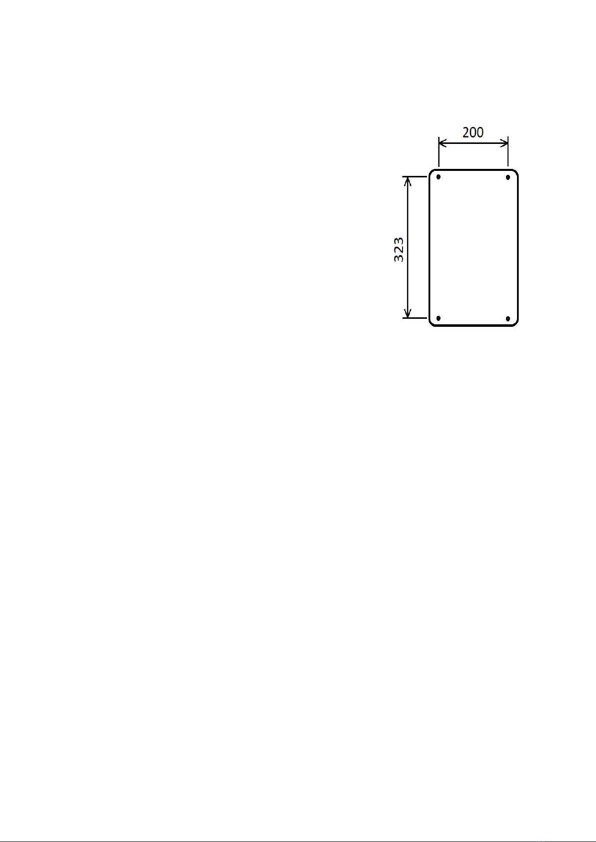
Instructions -
1. Pedestal Installation
Lead the power and communication lines through the
holes in the pedestal, Mount the pedestal on an
assembled concrete base, fix it firmly and ground it (by
connecting the grounding conductor and terminal - e.g. of
the SP 1 type - to the ground nut).
Wallbox Installation
Drill holes to anchor the wallbox charger, proceed In line
with the Figure 1. Holes’ diameter and depth depend
on the anchors used. Afterwards, insert anchors into these
holes.
2. Dismantle the charger’s lid (4 head screws by the PH2
screwdriver). From the control unit (CCU1) remove both
of the green connectors by pulling (MAIN CONNECTOR,
AUXILIARY CONNECTOR). If it is difficult, try to pull
them out of each end. Unscrew the lid grounding (green-
yellow jumper wire).
3. Screw the supplied cable glands onto the charging station and tighten them firmly.
4. Lead the power cord or communication cable through the cable glands and tighten them
firmly. Place the charger on the pedestal or wall, align it with the installation holes, and
screw it firmly.
5. Shortened the power and communication cables to the required length (sufficient to reach
the X1 / X3 terminal blocks) and strip the individual wires at their ends accordingly to avoid
exposed cores hanging out from the terminal. Afterwards, connect all the cores to the X1 or
X3 terminal according to their colour and tighten the screws firmly (Figure 3).
6. Disconnect the FA1 circuit breaker (by switching its control lever downward), connect the
FI1 residual current circuit breaker (by switching its control lever upward). Check the
connection of the power cord visually, and check that the charger is in a perfect condition. If
everything is OK, connect the power supply through the power cord (by operating your
power switch) . !!! CAUTION The Charging Station Is Now Energized. Care should be
taken to avoid contact with live parts!!! You can check for the presence of voltage by
using a suitable metering instrument on the X1 terminal. If the voltage is present on all
phases, press the test button on the FI1 residual current circuit breaker to check its operation.
It should be shut down immediately. Otherwise, do not use the charger! It is necessary to
disconnect it from the power supply and return it to the vendor for a refund.
7. Switch off power (using your power switch, check that the charger is really not under
power), switch on the FA1 circuit breaker and FI1 residual current circuit breaker again.
Insert both green connectors (MAIN CONNECTOR and AUXILIARY CONNECTOR) into
11/24
F
i
g
u
r
e
1
.

the control unit (CCU1) and tighten the yellow-green protective conductor to the cabinet lid
(which you disconnected in step 2).
8. Screw the lid onto the charging station. Before that, however, check the sealing rubber that
must be inserted and not twisted in its groove inside the charger’s lid, whose both end points
must slightly overlap and be placed from the bottom of the charger. Turn on the power
switch. If you have done all the steps correctly, LED signalling will light up on the charger’s
lid.
12/24

How to Use the Wallbox Charger Correctly?
User Instructions
i
!
The use of the charging station is very simple:
1. The charging station is ready for use when the front panel lights are lit
green. If it is lit red, the station is probably out of order, and it is
recommended to notify the station owner of this situation. (Remark: Panel
lights can lit red while booting for a moment.)
2. Unwind the cable from the charging station and check the charging
connector to see if is contains traces of dirt, e.g. mud or snow. If so, do not
use the connector. Inform the station owner and get another charger. If the
connector contains traces of water, tap the connector to remove it.
3. Plug the charging connector into a parked vehicle. Charging starts in few
seconds, which is indicated by an orange colour slowly fading in and out
during the charging process. This indicates that the vehicle is charging is
everything is OK.
4. If the colour switches to blue during charging, this indicates that the power
has been interrupted briefly by the station owner to prevent overloading of
the mains. Red colour - continuous or flashing - indicates an error. Inform
the station owner of this situation We recommend that you try to charge
your vehicle at another ejoin charging station to identify the source of the
error (station or car).
5. Steady orange light indicates that it is fully charged. You can cancel the
charging at any time as instructed by the manufacturer of the vehicle.
6. When the charging is complete, wrap the cable around the charging station
and leave the connector at a sufficient height above the ground to prevent
contamination.
13/24

Charging Station Additional Instructions
i
!
0
What to Do After the Installation or If an Error Occurs
After the installation and electrical inspection, turn on the charging station power
supply. The power cord should not be plugged in the vehicle! Check the LEDs
located on the front panel. After a brief red light (for few seconds) the colour should
turn green, which indicates that all of the internal tests of the station are OK and it
is ready for use. Blue colour is also OK, but only if the charging is disabled via
station remote controls.
If the LEDs do not come on at all, check again your switchboard that it is
connected to the power supply accordingly. At the same time, check for the
presence of voltage at all phases. If everything is OK, use electricity meter’s
Modbus communication interface to read the phase voltage in the charging station
again (applicable only to „J“ version of charger). If this is unsuccessful, turn off the
power supply, remove the lid (following the instructions given in step 2 of the
station installation instructions). Check that the FA1 circuit breaker and FI1 residual
current circuit breakers are turned on. Apply power to the charging station and read
the presence of phase voltage in the terminal block. If the electricity meter’s display
lights up, this indicates a presence of the supply voltage in the charging station.
Before you plug in the MAIN CONNECTOR and AUXILIARY CONNECTOR to
the control system and putting the lid on, turn off the power supply again. Turn it on
again once you re-assemble the lid on the charging station.
If the red light is on continuously, contact ejoin to arrange further actions.
If the red light is flashing, turn off the power supply, remove the lid, and make
sure that the right connector with wires leading to the X2 terminal is connected to
the BI1 residual current monitor. In addition, make sure that the AUXILIARY
CONNECTOR on the CCU1 is properly connected.
Test the charging station by connecting it to an electric vehicle whose battery has
been at least partially depleted and which you know for certain is capable of
charging correctly. Observe the steps given in the previous chapter ‘User
Instructions’. When you plug in the charging connector, you should be able to hear
a locking sound of the vehicle’s connector and then the sound of the charging
station’s contactor. Check the charging process using the vehicle’s on board
computer. At the same time, you should be able to remotely monitor the
consumption and other mains parameters using the electricity meter Modbus
communication interface (phase voltages, and the like.).
14/24

Servicing
!
0
To maintain the highest safety standards and avoid personal injuries and damage to
adjacent property, it is necessary to service the charging station at regular intervals.
Some of the listed actions may only be performed by a person with a valid license
in the given field, and they can be done during a regular inspection. The table is not
exhaustive, the list of all actions of a regular mandatory inspection is given in the
applicable standards.
Test Scope Action Interval
Residual Current Circuit
Breaker Test
Test the operation of the
residual current circuit
breaker using the button
on the breaker while its
top lid is removed and
power supply connected.
Every 6 Months
Charging Cable Visual
Test
Test the insulation /
connectors visually for
any damage and/or large
traces of contamination.
Every 3 Months
Lid / Cable Glands /
Screw Torque Test
Test all screws of the
cabinet lid and cable
glands for their torque
and protection against
water and dust.
As Needed
15/24

Warranty
i
!
The manufacturer provides a 24-month warranty on the charging station as a whole
from the date of purchase (as indicated on the receipt). The warranty can be claimed
directly at the ejoin company, which will contact you to arrange further actions.
The manufacturer reserves the right to reject warranty and shall not be held
liable for any and all damages and/or losses suffered on the charging station
and/or vehicles resulting from:
Failure to observe the storage requirements
Unprofessional installation, failure to observe installation instructions
and/or implementing unauthorized actions on the charging station
Failure to observe manufacturer’s operating/installation requirements,
instructions, and recommendations during the installation or operation of the
charging station
Unauthorized use or misuse of the charging station
Failure to place the charging cable as instructed
Failure to use the charging station as intended
Provide evidence that the charging station was installed and inspected by an
electrical inspector with a valid license and later that it was serviced at
regular intervals as specified by the manufacturer if applicable
16/24

Final Information
Warning
!
0
If any errors and failures occur during the operation of the charging station
(the equipment does not work, it is not working as intended, or you register a smoke
or other indications of a possible failure while using the charging station), try to
shut down the charging station immediately as instructed by disconnecting it
from the power system (by switching off the upstream circuit breaker in your
switchgear, and taking all actions to avoid its accidental start-up by anyone around).
Afterwards, contact your vendor or the original manufacturer and arrange further
actions. !!! Never try to repair the equipment by yourself!!!
Product Designation
i
All ejoin Charging Stations bear a label (Product Label) in line with the following
template:
17/24

Regular Inspection Specific Instructions
!
0
The charging station must undergo regular inspections and testing in line with the
applicable standards and regulations by a person possessing a mandatory license
and qualification. Information contained in this section are for professionals only.
Power Cable Insulation Resistance Test
In a voltage-free state, switch off the FI1 residual current circuit breaker and the
FA1 circuit breaker.
Charging Cable & Connector Insulation Resistance Test
The test is conducted in a voltage-free state, when the L1, L2, L3, and N conductors
are disconnected by the contactor. At the same time, it is required to disconnect the
MAIN CONNECTOR of the control system, which will disconnect the CP
conductor from the control system. The PE protective earthing wire remains
connected to the power frame and power PE conductor. The insulation resistance
between the PP (if applied to the terminal) and PE conductors is not measured,
because a small impedance is connected between them (of approx 220Ω, may be
tested by a multimeter).
Residual Current Protection
This protective function is provided by the FI1 residual current circuit breaker (of
the A type, < 30mA ~) and B1 residual current monitor (<30mA ~, <6mA =). The
components given in the B1 monitor specifications replace the type B residual
current circuit breaker and provide the mandatory protection in line with the IEC
61851-1 or IEC 60364-7-722 Standard.
Only the operation of the FI1 residual current circuit breaker is tested in this step
while powered, since the charging station tests and calibrates the B1 monitor
automatically each time before the KM1 contactor is switched on in line with the
monitor manufacturer’s recommendations.
Earthing
The charging station has a galvanically isolated low voltage source whose negative
pole is connected to a protective earthing conductor (PE) – but only if the MAIN
CONNECTOR is connected to the CCU1.
18/24

Technical Information
Mechanical Information
Working Position Vertical
Assembly Pedestal
Wallbox Vertical
Means of Anchorage 4x Screws
Charging Cable Placement Winded Around the Charging Station
Charging Station Height Height Between 1 - 1.5m
Adjacent Objects Minimum Distance At Least 20cm From Edges
Instrument Cabinet Material Aluminium
Minimum Post-Installation IP Protection IP54
Mechanical Strength IK10
Dimensions (W/O Pedestal) 380x235x120mm
Weight (W/O Pedestal) To Be Added
X1 Power Supply Terminal For Conductors of up to 10mm² Cross-Section
Electricity Meter Modbus Communication
Interface Terminal & X3 Remote Charging
Switch
For Conductors of 0.22mm² - 4mm² Cross-
Section
Power Cable Gland PG25
Communication I/O Cable Gland (If Included) PG13.5
Pedestal (If Included)
Pedestal Dimensions 160x100mm
Base Dimensions 300x180mm
Base Mounting Hole Diameter 12mm
Weight To Be Added
19/24

Earthing Recommendation: SP 1 Terminal Attached to
the Pedestal
Power Specifications
Power Supply System 22kW Version:
3x400V/230V/50Hz TN-C-S/TN-S/TT/IT
7kW Version:
230V/50Hz TN-C-S/TN-S/TT/IT
Power Supply Connection Type 22kW Version:
3P+N+PE
7kW Version:
1P+N+PE
Supply Voltage Tolerance 10%
Supply Voltage Frequency Tolerance 1%
Maximum Charging Current / Power 22kW Version:
32A/22kW
7kW Version:
32A/7.36kW
Maximum Charging Current Settings Wallbox:
N/A; Fixed Value of 32A (Current provided by
the charger to the vehicle. Actual value
depends on the vehicle’s specifications).
Charger:
Settings range from 6 to 32A via service menu
if the charging station is equipped with a
GPRS module or Wi-Fi; optional remote
settings.
Charging Station Idle Power Consumption (W/
O Charging)
Less Than 8W
Charging Mode 3
Charging Connector IEC 62196 Type 2 (Included Along W/ the
Cable)
Residual Current Device (RCD) Integrated & Compliance W/ STN EN/IEC
61851-1, < 30mA AC, < 6mA DC
Surge Protection Not included in the charging station, it is
necessary to install an upstream fuse or 32A
circuit breaker with a type B breaking and a
20/24
This manual suits for next models
3
Table of contents


