ZIV 5EVM User manual

Instructions Manual for 5EVM Recharging Points
M5EVM2011Iv00
Rev. 00, May 2021 ©ZIV APLICACIONES Y TECNOLOGÍA, S.L.U. 2020
5EVM
Electric Vehicle Home
AC Charging Station

I M5EVMD2011I
5EVM-D: Electric Vehicle Home AC Charging Station
© ZIV APLICACIONES Y TECNOLOGÍA, S.L.U. 2020
Table of Contents
1. Introduction............................................................................................................. 1
1.1 Model Selection ........................................................................................................ 1
2. Technical Data ........................................................................................................ 2
3. Standards and Tests .............................................................................................. 4
4. Physical Architecture and Mounting .................................................................... 5
4.1 Description................................................................................................................ 5
4.2 Mounting ................................................................................................................... 6
4.3 Connection Elements................................................................................................ 8
4.3.1 Equipment Power Supply ......................................................................................... 9
4.3.2 Vehicle Power Supply............................................................................................... 9
4.3.3 Pilot Wire (CP) .......................................................................................................... 9
4.3.4 Communication of the Recharging Points Network.................................................. 9
4.3.5 USB Port ................................................................................................................... 9
4.3.6 Domestic Charge Measurement............................................................................. 10
4.4 Safety Precautions and Maintenance Operations .................................................. 10
5. Operation............................................................................................................... 11
5.1 EV Charging ........................................................................................................... 11
5.2 Authorized Use ....................................................................................................... 11
5.3 Bluetooth................................................................................................................. 12
5.4 Residual Current Device (RCD) ............................................................................. 12
5.5 Reconnector ........................................................................................................... 12
5.6 Domestic Load Balancing (optional on PREMIUM Model)..................................... 13
6. HMI and Screen Tree ............................................................................................ 14
6.1 HMI Characteristics ................................................................................................ 14
6.2 HMI Screens ........................................................................................................... 15

5EVM-D · Electric Vehicle Home AC Charging Station
1 M5EVMD2011I
5EVM-D: Electric Vehicle Home AC Charging Station
© ZIV APLICACIONES Y TECNOLOGÍA, S.L.U. 2020
1. Introduction
The 5EVM family of charging points offers efficient recharging of electric vehicles. Its design,
size and robustness make it an ideal product for installation in home or business garages.
Main characteristics of this family of charging points:
- Robust and elegant design.
- Ease of installation and use.
- Security both in use and in installation.
- Efficiency and optimization of recharging.
1.1 Model Selection
All models have LCD display, LED indicators, RFID reader, RS485 port and a Class B(A) 2(R)
meter. The Domestic family is deployed in 2 units, both single-phase single plug:
- The Basic recharging terminal has everything necessary for a residential use.
- The Optimum version brings more comfort and efficiency, thanks to the use with
smartphone via a Bluetooth App, and the possibility to optimize the vehicle charging
according to the consumption of the installation.
If you have purchased a Basic unit, you should know that it is possible to upgrade to the
Optimum version.
DOMESTIC
BASIC
OPTIMUM
Single-Phase
YES
YES
Single Plug
YES
YES
Bluetooth
NO
YES
Residual Current Device (RCD)
OPTIONAL
OPTIONAL
Load Balancing
NO
OPTIONAL
When selecting the charger model, the power contracted at the place of installation must be taken into
account.
The performance of load balancing requires the optional "Home AC" accessory, which enables smart
charging by regulating the output power according to the home consumption of other loads.
The higher the output power, the faster the vehicle will charge. This function allows the user to make an
efficient consumption without reducing comfort and without the need to modify the power term of its
installation.
There are additional options, such as Modbus, that can be enabled by certificates. Contact ZIV for more
details.

Instructions Manual for 5EVM-D Models
M5EVMD2011I
5EVM-D: Electric Vehicle Home AC Charging Station
© ZIV APLICACIONES Y TECNOLOGÍA, S.L.U. 2020 2
2. Technical Data
The power supply line from the distribution box to the charging point must
comply with electrical safety standards, according to the regulations of each
country.
Remember that the equipment is Cat II (Overvoltage Category). Depending on
the location, it may be necessary to install an external overvoltage protection to
the device.
AC Power Supply 230 V 50 Hz (±10%)
Single-Phase or Three-Phase.
Overvoltage Category Cat III.
Output Maximum Power
Three-Phase 22 kW
Single-Phase 7.4 kW
Consumption on standby
Three-Phase <1.5 W / per phase (@230V)
Single-Phase <1.5 W (@230V)
Maximum Output Current 32 A per phase / plug.
Insulation Class Class 1.
Charging System Mode 3.
Connection to Power Supply Permanent.
Protection Level IP 54 / IK 08
Installation Mode Wall-mounted
3 fixing points
HMI Display 22 x 70 mm
4push-bottoms.
2Status LEDs.
1Energy Pulses LED.

5EVM-D · Electric Vehicle Home AC Charging Station
3 M5EVMD2011I
5EVM-D: Electric Vehicle Home AC Charging Station
© ZIV APLICACIONES Y TECNOLOGÍA, S.L.U. 2020
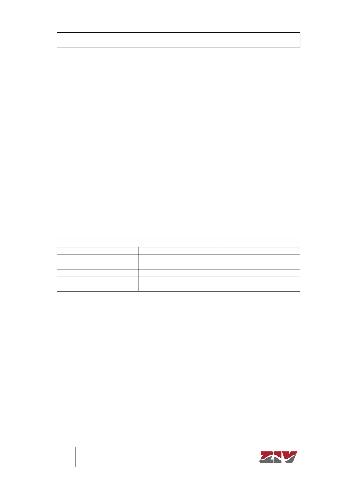
Dimensions 332 x 229 x 86 mm
(see drawings at the end of this document).
Weight < 2.5 kg
Connectors Types 2 xRJ-11(RS-485)
1 x2-pin male connector (Home AC).
1 xUSB-C (no function at the moment).
1 x6-pin male connector (Pilot Wire).
(PWM Signal).
Operation Range -25º to 40ºC
5% a 95% non-condensing.
The equipment's auxiliary elements must fulfill the following additional
requirements according to standard IEC 61851-1:
1. Fault protection.
a. Fault protection shall consist of one or more protective measures as
permitted according to IEC 60364-4-41. Detailed specification in section
8.3 of IEC 61851-1.
2. Residual current protective devices (RCD).
a. The connecting point of the EV supply equipment shall be protected by an
RCD having a rated residual operating current not exceeding 30 mA.
b. RCD(s) protecting connecting points shall be at least type A and fulfill the
standards specified in section 8.5 in IEC 61851-1 (Fulfillment
of IEC
61008-1, IEC 61009-1, IEC 60947-2 y IEC 62423, etc.).
3. Conductive Electrical interface requirements.
a. The standard accessories shall be in accordance with IEC 60309-1, IEC
60309-2 or IEC 60884-1 or the national standard.
b. Basic interface: The basic interface is specified in 6.5 of IEC 62196-
1:2014.
4. Cable assembly requirements.
a. The cable assembly shall be provided with a cable that is suitable for the
application.
b. The technical requirements of the cable are detailed in section 11 of IEC
61851-1 (Electrical Rating, Dimensions, Strain Relief, etc.)
5. Characteristics of mechanical switching devices.
a. For AC applications, switches and switchdisconnectors shall have a rated
current, at a utilization category of at least AC-22A.
6. Characteristics of circuit breakers.
a. Circuit breakers, if any, shall comply with IEC 60898-1 or IEC 60947-2 or
IEC 61009-1.

Instructions Manual for 5EVM-D Models
M5EVMD2011I
5EVM-D: Electric Vehicle Home AC Charging Station
© ZIV APLICACIONES Y TECNOLOGÍA, S.L.U. 2020 4
3. Standards and Tests
The tests carried out are based on the following standards:
IEC 61851-1: 2017 Electric vehicle conductive charging system. Part 1: General Requirements.
IEC 61851-21-2: 2018 Electric vehicle conductive charging system. Part 21-2: Electric vehicle
requirements for conductive connection to an AC/DC supply - EMC requirements for off board
electric vehicle charging systems.
IEC 60068-2-30 (Test Db) Environmental testing - Part 2-30: Tests - Test Db: Damp Heat cyclic
(12 h + 12 cycle).
IEC 60068-2-1 (Test Ad) Environmental testing - Part 2-1: Tests - Test A: Cold.

5EVM-D · Electric Vehicle Home AC Charging Station
5 M5EVMD2011I
5EVM-D: Electric Vehicle Home AC Charging Station
© ZIV APLICACIONES Y TECNOLOGÍA, S.L.U. 2020
4. Physical Architecture and Mounting
4.1 Description
The mechanics of the device are based on the following parts:
- Base. Part that is attached to the wall.
- Front. Hides the active parts of the equipment and is attached to the base.
- Wire cover. Provides access to the electrical connection, communications and
configuration parts. In this way, there is no access to the internal parts either in the
installation or in the configuration of the equipment. This cover can be sealed with two
screws.
- Embellishment. Most visible part of the equipment, it offers the finishing line.
Figure 1. 5EVM's Mechanical Architecture.

Instructions Manual for 5EVM-D Models
M5EVMD2011I
5EVM-D: Electric Vehicle Home AC Charging Station
© ZIV APLICACIONES Y TECNOLOGÍA, S.L.U. 2020 6
When you receive the equipment, and before its installation, perform the
following checks:
1. The equipment model corresponds to the specifications of your order.
2. The equipment is in perfect mechanical condition and there are no shocks or
loose parts.
4.2 Mounting
Installation is wall mounted. The surface of the wall where the equipment is placed must be
resistant both for fixing the device and for supporting its weight.
When installing the equipment, it is convenient to respect some minimum distances for safety
and to guarantee the installation and maintenance activities. The height for fixing the equipment
is recommended between 750 and 1200 mm, leaving 250 mm on the other sides.
For wall mounting, the equipment has three fixing points, which are marked in blue in the
following image.
Figure 2. Rear Base of the 5EVM.

5EVM-D · Electric Vehicle Home AC Charging Station
7 M5EVMD2011I
5EVM-D: Electric Vehicle Home AC Charging Station
© ZIV APLICACIONES Y TECNOLOGÍA, S.L.U. 2020
For correct wall mounting, the following actions must be followed:
1. Upper fixing point: insert the plastic plug into the wall and then insert its screw so that its
head has a clearance of approximately 4 mm from the wall.
2. Place the recharging station on the screw. To do this, the screw head is positioned inside
the upper hole.
Figure 3. Form of Fixation.
3. Position the equipment so that it is vertical to the ground.
4. Lower fixing point. Insert the plastic plugs into the wall. Insert the screws with their
washers in each hole shown in the following image. Then screw them into the plastic
plugs to secure the unit to the wall.
5. The plugs, screws and washers supplied with the unit are used for this mounting.
Figure 4. Lower Fixing Points.

Instructions Manual for 5EVM-D Models
M5EVMD2011I
5EVM-D: Electric Vehicle Home AC Charging Station
© ZIV APLICACIONES Y TECNOLOGÍA, S.L.U. 2020 8
When installing and commissioning the equipment, follow the instructions described in the Low
Voltage Electrotechnical Regulations. The installation of the equipment requires an external
overcurrent protection (MCB) and a differential breaker (RCD).
4.3 Connection Elements
To access the connection, remove the front wire cover.
The connection blocks are as follows:
1. Equipment Power Supply.
2. Power supply to the electric vehicle (hose).
3. Pilot wire (CP).
4. Communication RS-485.
5. USB connector (no functionality assigned).
6. Connector for "Home AC" accessory (load balancing).
Figure 5. Connection Elements.
6
4
5
3
1
2

5EVM-D · Electric Vehicle Home AC Charging Station
9 M5EVMD2011I
5EVM-D: Electric Vehicle Home AC Charging Station
© ZIV APLICACIONES Y TECNOLOGÍA, S.L.U. 2020
4.3.1 Equipment Power Supply
The power supply is represented in Figure 5 by the connector 1.
The power supply is provided by screw terminals, which offer great mechanical robustness.
These terminals allow cable sections of up to 25mm2.
The equipment has the following terminals from left to right:
L1. Phase R.
L2. Phase S.
L3. Phase T.
N. Neutral.
GND. Ground.
The number of terminals may vary based on the model of the recharge point, as it can be
single-phase or three-phase.
4.3.2 Vehicle Power Supply
The power supply cables and the IEC62196-2 hose ground, which is connected to the vehicle,
are screwed into the terminals shown in Figure 5 as connector 2.
The equipment, depending on the version, has the following terminals from left to right:
GND. Ground.
L1. Phase R.
L2. Phase S.
L3. Phase T.
N. Neutral.
4.3.3 Pilot Wire (CP)
Represented in Figure 5 as connector 3.
This terminal block is dedicated to the following:
Connection of the pilot wire (CP) of the hose according to IEC 62196-2.
The "Control Pilot" wire is used to regulate the demand of the EV by means of a PWM signal.
4.3.4 Communication of the Recharging Points Network
Represented as connector 4 in figure 5, two RJ11 connectors are available for RS-485
communication.
4.3.5 USB Port
Connector without assigned functionality.

Instructions Manual for 5EVM-D Models
M5EVMD2011I
5EVM-D: Electric Vehicle Home AC Charging Station
© ZIV APLICACIONES Y TECNOLOGÍA, S.L.U. 2020 10
4.3.6 Domestic Charge Measurement
The connector, identical to connector 6 in Figure 5, is specific to the HOME AC or load
balancing accessory. This functionality allows to adapt the power used during the recharge of
the vehicle to the consumption of the house, allowing an intelligent and efficient charge to avoid
as far as possible the obligation of the user to increase the contracted power of the recharging
point.
See, at the end of this manual, specific information on this functionality and the characteristics
of the accessory supplied with the charger if the model purchased includes it.
4.4 Safety Precautions and Maintenance Operations
When handling the equipment for installation, commissioning or maintenance, keep in mind
that:
1. The installation of the recharging point is subject, in a generic way, to the
compliance of all the safety and occupational risk prevention measures that
the company responsible for the installation of the recharging point has
established for this work environment and the safety standards.
2. Specifically, only qualified personnel should carry out the installation and
handling of the equipment, and the operating environm
ent should be
appropriate for the 5EVM
equipment, ensuring compliance with the
conditions indicated in Point 2.
3. Before manipulating or modifying the connection, remove the power supply.
Handling the equipment while it is connected can be dangerous.
4. Incorrect handling or installation of the equipment can cause damage, both
personal and material. Read this instr
uctions manual carefully before
connecting the equipment.
Follow all installation and maintenance
instructions throughout the life of the equipment.
5. Do not use this equipment in charging modes not covered by IEC 61851
standard.
6. ZIV is not responsible for any damage to persons, facilities or third parties
resulting from failure to comply with points 1,2 and 3.
The equipment does not require any maintenance operation except for the periodic checks
stipulated by the regulations in force.
1. Check the installation according to the inspections required by law.
2. Remove from service any element that is not in perfect condition and could
be dangerous, call a qualified technician.
3. Do not use the equipment if the housing or the connector of the EV is broken
or shows any sign of damage.

5EVM-D · Electric Vehicle Home AC Charging Station
11 M5EVMD2011I
5EVM-D: Electric Vehicle Home AC Charging Station
© ZIV APLICACIONES Y TECNOLOGÍA, S.L.U. 2020
5. Operation
The recharging points, depending on the model, have some or all of the functionalities
described below.
5.1 EV Charging
This is the basic functionality. All of the family's recharging points offer vehicle recharging in
mode 3 (according to IEC61851-1).
The equipment informs of the recharge status by means of display and LED lighting.
Charging process:
1. To start a charge, check that the device is Available: LEDs are lit in fixed green and the
display shows the Default Screen.
2.
Pass a RFID card in front of the reader: the LEDs flash yellow and the display shows
STARTING SESSION. After a few seconds, the LEDs
turn to fixed white and the
display shows Main Menu without load:
CHARGE NOW / PROGRAM CHARGE /
CONFIGURATION / GENERAL.INFO.
3. Select CHARGE NOW
. The LEDs will now flash yellow and the display will show
PLUG CONECTOR.
4. Connect the hose. Charging begins immediately: LEDs turn to fixed blue and display
shows "Energy", "Power", "Time" (i
f there is no consumption the LEDs are blue
flashing).
5. To end the session, pass the same RFID card through the reader: the LEDs turn to
fixed white and the display shows the Main Menu during charging: STOP CHARGE /
CONFIGURATION / GENERAL.INFO.
6. Select STOP CHARGE: the display shows the SUMMARY SESSION ("Energy”,
“Time”), LEDs fixed white.
7. Disconnect hose. After 30 seconds, the device is available again: fixed green LEDs
and Default Screen.
5.2 Authorized Use
The charging point is configurable so that it can only be used if the user has previously
authenticated. There are, depending on the model, different types of authentication:
- RFID card. The user has a unique RFID card. By passing this card through the reader of
the equipment, the user is authenticated and can use the equipment.
- Bluetooth. User authentication is performed in the synchronization of the mobile
application.

Instructions Manual for 5EVM-D Models
M5EVMD2011I
5EVM-D: Electric Vehicle Home AC Charging Station
© ZIV APLICACIONES Y TECNOLOGÍA, S.L.U. 2020 12
5.3 Bluetooth
The equipment features Bluetooth communications, so that the user can manage the recharge
point through a ZIV application.
Through this interface, the user can carry out the basic configuration of the equipment, start or
stop a recharge or consult the recharges historical log.
5.4 Residual Current Device (RCD)
The installation of the recharging points implies an alternating current differential electrical
protection, so that if a residual current of more than 30mA is exceeded, the protection acts with
the aim of protecting the safety of people.
However, if there is an insulation failure in the vehicle that involves a leakage of direct current,
the differential protection could be inhibited, which would lead to a lack of protection that would
have a negative impact on safety.
If this functionality is available, the recharging point performs a monitoring of the DC residual
current when it is charging a vehicle and, if it exceeds 6mA, the recharging point stops the
recharge. In this way, the AC differential protection is not inhibited at any time.
5.5 Reconnector
When it comes to installing a charging point in the home environment, the majority opts for
scheme 2 (according to the Spanish regulation ITC-BT-52), so that the charging point is
installed downstream of the home meter. In this way, the user uses the same electric meter for
both the home and his electric vehicle.
The new smart meters that are installed in our homes integrate a power circuit breaker (CB), so
that they cut off the electricity supply when a house demands more power than the contracted
power. When this situation occurs, the CB remains open until the meter detects that there is no
load connected. When all the loads have been disconnected, the meter can reset its CB.
In order to reset the CB, the user must open the general switch of his house, unlatching all the
loads hanging from the meter and keeping it in that state for a few seconds. Then, the electric
meter can reset the power supply. Once the user proceeds to close the breaker, the electric
energy is again available in your home.
If we introduce a recharge point in another circuit that starts from this home meter (scheme 2),
we find the problem that we also have to disconnect the recharge point from the grid so that the
meter can restore the electricity supply after a disconnection through the ICP.

5EVM-D · Electric Vehicle Home AC Charging Station
13 M5EVMD2011I
5EVM-D: Electric Vehicle Home AC Charging Station
© ZIV APLICACIONES Y TECNOLOGÍA, S.L.U. 2020
That is why, when the ICP acts, the user would have to
1. Turn down the home switch.
2. Go to where the recharge point is installed to disconnect it from the grid.
3. Reconnect the recharge point to the grid.
4. Raise the differential of the house.
Bearing in mind that the recharge point is installed in the vehicle's garage, the potential
discomfort generated for the user every time the CB is opened is evident.
Although there is the possibility of feeding the recharging point from a magnetothermic installed
at home, this solution has the disadvantage that the installation and the corresponding cable run
must be carried out from the home to the garage, with the cost and potential difficulties that this
operation may involve.
The ZIV's new family of recharging points, however, has implemented a functionality that is
designed specifically for this case of use.
Based on this functionality, the equipment is "disconnected" from the grid when the CB cuts the
power supply and automatically connects when it is restored. This operation will be performed in
a transparent manner for the user, so that their action to CB operations will not require any
action other than acting on the house switch.
5.6 Domestic Load Balancing (optional on PREMIUM
Model)
This functionality is optional for the user. Remember to ask ZIV for the 5EVM
model that includes it and the necessary accessory for its operation.
In installations carried out according to Scheme 2 (according to ITC-BT-52), there is a potential
problem that the meter will cause the internal CB to open as a result of overconsumption.
The recharge of an electric vehicle implies a substantial power consumption for a domestic
environment, so by adding this consumption to that of the home, the contracted power could be
exceeded in a recurrent manner. This feature allows to adapt the power used to recharge the
vehicle to the consumption of the home. The purpose of this feature is that the recharge of the
vehicle is not the cause of the action of the meter's CB and that, consequently, it is not
necessary to increase the contracted power.
If the house demands excessive power, the equipment will reduce the power used to recharge
the vehicle so that the contracted power is not exceeded. Similarly, if consumption at home is
low, it will use all the available power to recharge the vehicle in the shortest time possible.
To carry out this function, there is an accessory that is installed on the output of the house
meter. This accessory measures the instantaneous consumption and the 5EVM, with this
information and knowing the contracted power, dynamically modifies the power used for
recharging the vehicle.

Instructions Manual for 5EVM-D Models
M5EVMD2011I
5EVM-D: Electric Vehicle Home AC Charging Station
© ZIV APLICACIONES Y TECNOLOGÍA, S.L.U. 2020 14
6. HMI and Screen Tree
6.1 HMI Characteristics
HMI Elements:
1: Display.
2,3,4 and 5: Buttons.
6: RFID Reader.
7: LEDs Status.
8: Metrology LED.
Figure 6. HMI Components.
The display is a dot matrix type of 132 mm x 42 mm, with an active area of approximately 22
mm x 70 mm. Depending on the font size, it contains up to 3 lines with 21 characters each. The
display has a backlight and reflects the external light to prevent the solar radiation from having a
negative effect on the appearance and reading.
The HMI consists of 4 buttons: up (2), down (3), accept (5) and escape (4).
For the single-plug charger, the 2 status LEDs light up at the same time (for the dual-plug
charger they light up independently for each plug). These LEDs are RGB and their operation
depends on the screen displayed and the status of the EV.
Default Screen
There is an inactivity time of 30s, so that the equipment switches to the default screen if there is
no user interaction during that time. This screen change is carried out on all screens except the
Out of service screen.
The default screen after inactivity will vary depending on the state of the equipment:
- There is no charging session: Start.
- Charging session open: Charging in progress.
When the inactivity time is reached, the display backlight will also be turned off (even when the
display is the one referred to Out of Service).
A recharge start will only take place when the display is Plug Connector and in the case where
"free_charging_mode" = on, also from Start.
If the VE is disconnected (Pilot Control in 'A' status), the device will go to Stopping Session
regardless of the screen being displayed at that time.

5EVM-D · Electric Vehicle Home AC Charging Station
15 M5EVMD2011I
5EVM-D: Electric Vehicle Home AC Charging Station
© ZIV APLICACIONES Y TECNOLOGÍA, S.L.U. 2020
6.2 HMI Screens
Start
2019/10/20 10:33
Wallbox 4.0
You will return to this screen from any other due to inactivity
(30 sec).
By default, the date and time will be displayed, and "Wallbox
4.0".
The backlight will be off by default.
LEDs Color
Green.
Button Action
It activates backlighting with a 30s inactivity time.
The screen shows Swipe card through reader.
RFID Action
If the user is authenticated to Starting Session.Otherwise, to
Nor Authorized User.
EV Action
- “free_charging_mode” = on and change to ‘B’ or ‘C’ state.
Starts the preferred recharge. The screen will depend on
the type of recharge:
oProgrammed charge: Waiting for charging start.
oImmediate charge: Charging in progress.
- “free_charging_mode” = off. None.
RFID Authentication
SWIPE CARD
THROUGH READER
Indication for authentication before login.
LEDs Color
White.
Button Action
ESC Goes to Start screen.
RFID Action
Authentication is performed:
- Failed authentication Nor Authorized User.
- Successful authentication
- without charging session Main menu without
recharging.
- open charging session Main menu during
recharging.
EV Action
- Open charging session:
oChanges to ‘A’ state Stopping Session.
oChanges to other states None.
- Without charging session None.

Instructions Manual for 5EVM-D Models
M5EVMD2011I
5EVM-D: Electric Vehicle Home AC Charging Station
© ZIV APLICACIONES Y TECNOLOGÍA, S.L.U. 2020 16
Starting Session
STARTING
SESSION
Login authentication message of a user through RFID. Only
displayed if it is a back-end authentication and if no charge is
active. In case of active charge, the back-end is never asked,
only verified that it is the same card that started the charge
process.
LEDs Color
White.
Button Action
ESC Goes to Start screen.
RFID Action
Authentication is performed:
- Failed authentication Nor Authorized User.
- Successful authentication
- without charging session Main menu without
recharging.
- open charging session Main menu during
recharging.
EV Action
- Open charging session:
oChanges to ‘A’ state Stopping Session.
oChanges to other states None.
- Without charging session None.
Nor Authorized User
NOT AUTHORIZED
A message is displayed indicating that the card is not
authorized at the Recharging Point.
After about 5s, it will return to Start.
LEDs Color
White.
Button Action
ESC
Goes to Start screen.
RFID Action
None.
EV Action
- Open charging session:
oChanges to ‘A’ state Stopping Session.
oChanges to other states None.
- Without charging session None.

5EVM-D · Electric Vehicle Home AC Charging Station
17 M5EVMD2011I
5EVM-D: Electric Vehicle Home AC Charging Station
© ZIV APLICACIONES Y TECNOLOGÍA, S.L.U. 2020
Main menu without recharging
CHARGE NOW
PROGRAM CHARGE
CONFIGURATION
GENERAL.INFO
To see all the options, you must use the scroll buttons. The
setting option is shown for all users, the available options differ
depending on the user.
LEDs Color
White.
Button Action
ESC Goes to Start screen.
↑↓ Line selection.
OK Depending on the line where the cursor is, it goes to a
different screen:
- CHARGE NOW: Plug Connector.
- PROGRAM CHARGE: Establish programmed charge.
- CONFIGURATION: Configuration.
- GENERAL.INFO: General info.
RFID Action
None.
EV Action
None.
Main menu during recharging
STOP CHARGE
GENERAL.INFO
Using the scroll buttons, you can access both options.
LEDs Color
White.
Button Action
ESC Goes to Charging in progress screen.
↑↓ Line selection.
OK Depending on the line where the cursor is, it goes to a
different screen:
-
STOP CHARGE:
goes to
Summary session screen.
- CONFIGURATION: Configuration.
- GENERAL.INFO: General info.
RFID Action
None.
EV Action
Changes to ‘A’ state
Stopping Session.
Changes to other states None.

Instructions Manual for 5EVM-D Models
M5EVMD2011I
5EVM-D: Electric Vehicle Home AC Charging Station
© ZIV APLICACIONES Y TECNOLOGÍA, S.L.U. 2020 18
Establish programmed charge
CHARGE
Start 01:00
End 07:00
This screen will display by default the start and end times of
charging that have been set in the last session and the option
to start charging (CHARGE).
LEDs Color
White.
Button Action
ESC
You go to previous editable position. If we are in
CHARGE goes to Main menu without recharging.
↑↓ Increase/decrease, for the time setting, the
value on
which the cursor is placed.
OK
It is validated and goes to the subsequent editable
position. If the cursor is in the last position, the set values are
saved and goes to Waiting for charging start, if the EV is
connected, or goes to Plug connector if it is not connected.
If no time is selected-> Invalid range.
RFID Action
None.
EV Action
None.
Invalid range
INVALID RANGE
This screen will be displayed when neither start nor end time
is set on a programmed charge.
LEDs Color
White.
Button Action
ESC
Returns to Establish programmed charge.
OK Returns to Establish programmed charge.
RFID Action
None.
EV Action
None.
Plug connector
PLUG CONNECTOR
Screen to detect the EV. When it is detected, it starts the
charging process.
If the EV is already connected, this screen does not appear.
LEDs Color
Blinking yellow.
Button Action
ESC
Goes to Start screen.
RFID Action
None.
EV Action
Changes to 'B' or 'C' state:
- Programmed charge: Waiting for charging start.
- Immediate charge: Charging in progress.
Table of contents