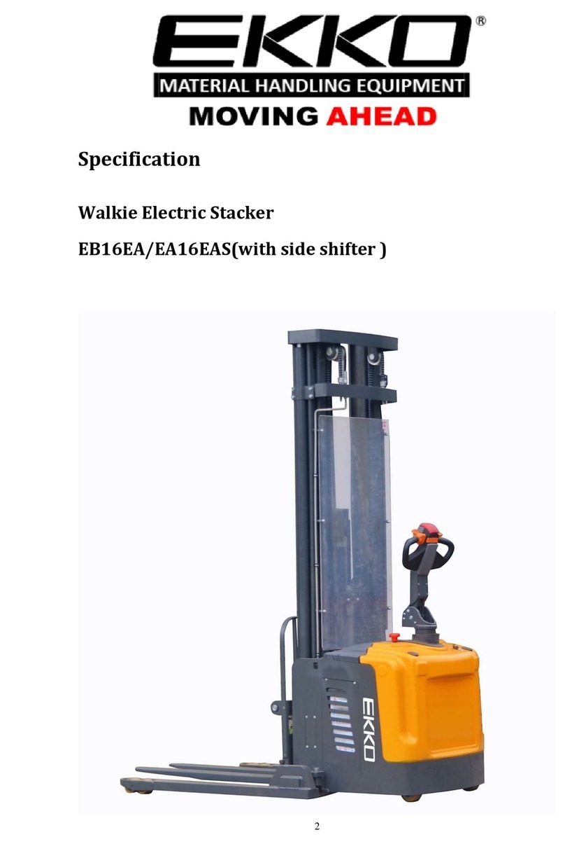
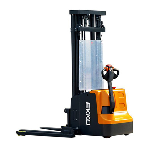
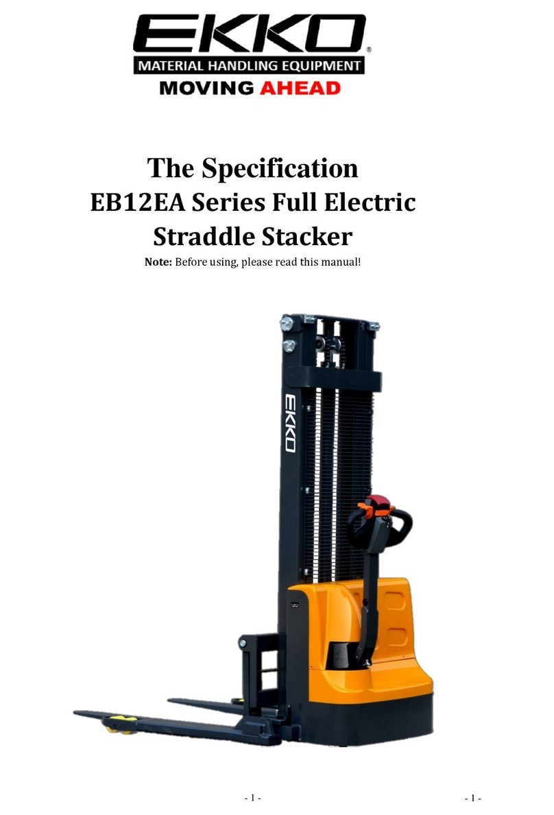
EKKO EA15B User manual

The Specification
EA15B Series Semi-Electric
Stacker
Note: Before using must read this manual and the various warning label!

- 1 -
Contents
Preface...........................................................................................- 2 -
1. Structural data form...................................................................- 2 -
2. Safety guidance.........................................................................- 3 -
3. Maintenance..............................................................................- 4 -
4. Control panel...............................................................................4/5
5. Troubles shooting......................................................................- 5 -
6. Parts List....................................................................................- 6 -

- 2 -
Preface
EKKO Lifts would like to thank you for your recent
purchase of our semi-electric stacker EA15B series. The stacker
is made of high-quality steel and was designed to give you a
durable, reliable and ease of use equipment. For your safety and
correct operation usage, please carefully read this instruction
manual and warnings on this stacker before use.
Note: All the information reported herein is based on data
available at the moment of printing. We reserve the right to
modify our products at any moment without notice and
incurring in any sanction. So, it is suggested to always verify
possible updates.
1. Structural data form
Model
EA15A (EA15B)
Load Capacity
(lb)
3300
Load Capacity on Max. height
(lb)
1980
Lifting height Max.
(in)
119.4
Load center distance
(in)
24
Fork length
(in)
45.3
Single fork width
(in)
3.94
Overall fork width
(in)
8-35
Lowered fork height
(in)
2..35
Fixed leg length
(in)
36.4
Fixed leg width, single
(in)
3.94
Width between fixed legs
(in)
35.4-59
Turning radius
(in)
53.2
Overall length
(in)
74
Overall width max
(in)
59
Extended mast height
(in)
140.5
Lowered mast height
(in)
84.5
Battery Voltage
(in)
12V/120AH,10-12V
Charger
12V/15A
Lift Motor
DC,12V/1.5KW

- 3 -
Service Weight
(lb)
1150
2. Safety guidance
2.1 Operator should read all warning signs and instructions on the stacker
before using it.
2.2 Do not operate a stacker unless you are familiar with it and have been
trained or authorized to do so.
2.3 Do not operate a stacker unless you have checked its condition. Give
special attention to the chain, the wheels, the handle, the guide frame, the
pilot wheel, the mast, battery, etc.
2.4 Do not use on a slopping ground or on in explosive dangerous
environment.
2.5 Do not ever lift people on the forks.
2.6 When forks are lifted, it is forbidden for anyone to stand under the
forks or pass through the forks.
2.7 The operator should use gloves for protecting.
2.8 Do not move the stacker when the goods are lifted to the height of
more than 11.8 in.
2.9 When the goods are lifted, people should stay clear from the forks of
at least 2 feet.
2.10 The weight of goods should be distributed onto both forks, do not
use only one fork. The center of gravity of goods should be in the center
of two forks of load center of 24”.
2.11 Do not overload maximum capacity.
2.12 Before using or charging it, check battery fluids, if it is insufficient,
please fill with only distilled water.
2.13 Charging the equipment should be in dry and ventilated location,
and far away from heat.
2.14 Always keep the forks in the lowest position if not in use.
2.15 The operator should always be responsible and careful when
operating the stacker.

- 4 -
3. Maintenance
3.1 Hydraulic oil
Please check the oil level every six months. The oil can be hydraulic oil:
ISO VG32, its viscosity should be 32cSt at 40oC, total volume is about
4.0 liters.
3.2 Daily check and maintenance
It is necessary to check the stacker daily. Special attention should be
to the wheels and axles of debris stuck in between which may block the
wheels. Check the forks and the mast, the chain, the battery should be
checked as well. The forks should be unloaded and lowered in the lowest
position when not in use.
3.3 Lubrication
Use motor oil or grease to lubricate all movable parts every 3 months.
4. Control panel
Pic.1
4.1 Emergency switch
Whenever you press this switch downwards, it will immediately switch
the power off, and when you pull the it back up it will switch the power
back on.
4.2 Voltage meter
It indicates the voltage of battery. When its voltage is less than 10 Volt,
you should recharge it.
4.3 Control handle
This control handle lowers and raises the forks.
4.4 Recharging socket

- 5 -
Plug the charger into any 110V outlet, then plug the charger into the unit of the
recharging socket. It will automatically stop charging when charge is complete.
5. Troubles shooting
No
Trouble
Cause
Solution
1
The forks can’t lift to the max.
height.
-Low on hydraulic fluid
-Add hydraulic fluid.
2
The forks cannot lift at all.
-No hydraulic fluid.
-The tank or fluid has impurities.
-Add hydraulic fluid
-Change fluid
3
Does not power up.
-The emergency switch is pressed
down
-The battery is too low.
-The connectors of electrical
wiring is loose.
-The contact of DC motor is bad.
-Pull emergency switch up.
-Charge it.
-Tighten the bolts.
-Replace with new one.
4
The forks cannot be
descended.
-The piston rod or mast is
deformed resulting from partial
loading slanting to one side or
over-loading.
-The fork was kept in the high
position for long time with
piston rod bared to arise in
rusting and jamming of the rod.
-The release valve of pump is not
opened.
- Replace with new one.
-Keeping the fork in the lowest
position if not using and pay
more attention to lubricate the
rod.
-Check it, if damaged, replace
with new one.
5
Leaks
-Seals are worn or damaged.
-Replace with the new one.
6
The fork descends by itself
-The impurities in the fluid
caused the release valve not
properly seal shut.
-Sealing parts worn or damaged.
-The release valve is damaged.
-Replace with new oil.
-Replace with the new one.
7
Battery cannot be charged
-Battery is bad.
-The charging plug is loose.
-Replace with the new one.
-Tighten the clamps or bolts
Note: Without authorization or training, it is strictly prohibited to repair!

- 6 -
6. Parts List
No.
Code
Name
Specificatio
n
Quantity
1
GB/T 818-2000
Cross recess pan head screw
M6×20
14
2
EA10.0-6
Guard clamp
6
3
EA1016.0-4
Protective cover
1
4
EA10.9-2
Electrical cover
1
5
GB/T 96.2-2002
Large (big) plain washer
φ6
6
6
GB 2674-86
Socket button head screws
M10×25
2
7
EA10.4-3
Cover
2
8
GB/T 276-94
Deep groove ball bearing
6205
8
9
GB/T 297-94
Tapered roller bearing
30205
2
10
GB/T 97.1-2002
Plain washer
φ24
3
11
EA10.6.1
Wheel frame welded parts of
driven pulley
1
12
EA10.4.1
Steering handle
1
13
EA10.4-1
Pin roll
1
14
GB 894.1-86
External circlip
φ10
4
15
GB 894.1-86
External circlip
φ12
3
16
EA 10.4-2
Connecting shaft
1
17
EA10.4-6
Spacer bush
2
18
EA10.4-7
Gas spring
1
19
EA10.4-4
Gas spring shaft
1
20
EA10.5-7
The push rod screw
1
21
GB_T 2084-94
Cylindroid helical-coil
compression spring
1
22
EA10.5-4
Skate brake
1
23
EA10.5-8
CAM pedal
1
24
EA10.5-3
Pin roll
1
25
GB/T 70.1-2000
Hexagon socket cap screws
M12×100
2
26
EA10.5.2
Nylon wheel
2
27
EA10.5-1
Bushing
2
28
GB/T 276-94
Deep groove ball bearing
6204
10
29
EA10.5-2
Axle sleeve
4
30
GB/T 93-1987
Spring washer
φ12
2
31
GB/T 6170-2000
Hex nut
M12
2
32
EA10.5.1
The brake wheel frame
welded pieces
1
33
ISO08A
Chain
2
34
EA10.5-5
Shaft filler washer
2
35
EA10.4-8
Steering chain
2
36
GB/T 1096-2003
General flat key
6×8
1
37
EA10.4.2B
The handle base
1
38
EA10.4-5
Steering shaft.
1
39
EA10.4.3-1,4
Draw-in bolt
4
40
GB/T 41-2000
Hex nut
M10
9
41
EA10.4.3-2
Strainer
2
42
GB/T 6176-2000
Hex nut
M18×1.5
1
43
GB/T 93-1987
Spring washer
φ10
7

- 7 -
44
GB/T 95-2002
Flat washer
φ10
5
45
CMB1-VB1303060-
120
pump station
1
46
TY-01.36
Emergency Stop Switch
1
47
TY-01.42
SPN charging plug
1
48
GB/T 818-2000
cross recess pan head screw
M4×20
4
49
GB 923-88
acorn nut
M10
1
50
GB 923-88
acorn nut
M8
2
51
GB/T 41-2000
Hex nut
M8
2
52
GB/T 93-1987
Spring washer
φ8
2
53
GB/T 95-2002
Flat washer
φ8
2
54
EA10.16.1
The door frame component
1
55
GB/T 5781-2000
Hex bolt thread
M10×55
1
56
EA10.0-2
Oil cylinder hoop
1
57
EA10.8-6
Fuel pipe union
1
58
GB/T 70.1-2000
Hexagon socket cap screws
M10×25
2
59
GB/T 97.1-2002
Flat washer
φ10
2
60
TY-01.43
Coulombmeter
1
61
EA 10.9.1
Distribution box
1
62
12V120Ah
Battery
1
63
EA10.8-2T
Block cover
1
64
EA10.8-3
Bushing
1
65
EA10.8-4
Oil cylinder
1
66
GB/T3683-92
High-pressure oil pipe
1
67
ISO12A
Chain
2
68
EA10.0-1
Chain pull rod
2
69
GB/T 6170-2000
Hex nut
M14
4
70
GB/T 93-1987
Spring washer
φ14
2
71
EA10.2.2-3
Footstock
1
72
GB/T 70.1-2000
Hexagon socket cap screws
M8×16
1
73
EA10.2-5(G)
Chain wheel
2
74
GB 894.1-86
Circlip for shaft
φ20
6
75
GB 893.1-86
Circlip for hole
φ47
2
76
EA 10.8-1
Piston rod
1
77
12V20A
Charger
1
78
EA10.8-5
Piston rod
1
79
EA10.8-9
Detent ring
1
80
EA10.0-1
Front wheel
2
81
EA10.0-3
Small shaft
2
82
EA10.3.1
Fork frame welded
1
83
EA10.3.2-2
Adjust baffle plate
2
84
EA10.3.2
Fork
2
85
EA10.3-2
Major axis
1
86
GB 894.2-86
Circlip for shaft
φ32
2
87
GB/T 77-2000
Hexagon socket set screw
with flat point
M12×20
4
88
EA10.3-1
Pallet rack roller
4
89
GB 894.2-86
Circlip for shaft
φ25
4
90
GB 893.2-86
Circlip for hole
φ52
4
91
EA10.3-3
Lateral pressure pad
4

- 8 -
Other manuals for EA15B
1
This manual suits for next models
2
Table of contents
Other EKKO Lifting System manuals
Popular Lifting System manuals by other brands

WERTHER INTERNATIONAL
WERTHER INTERNATIONAL 210I/42 Instruction and maintenance manual

Snorkel
Snorkel SL30SL operating manual

Challenger Lifts
Challenger Lifts CL12A Installation, operation & maintenance manual

LGMG
LGMG SR1018D Operation manual

Terex
Terex Genie TX-34/20 Service manual

BANDELIN
BANDELIN SONOREX TECHNIK MB operating manual