MONZUN M2, M3
07/2016 - 9 - NP-M2-M3-5_07-2016
OPERATION
6. PRODUCT OPERATION
Proper dryer operation depends on the compressor activity and does not require any operation. The
pressure vessel does not need to be drained as the compressed air into the air tank is already dried.
The working pressure settings for the pressure switch set by the manufacturer cannot be changed.
Compressor operation at lower working pressures than the switching pressure is evidence that the
compressor is overloaded (high air consumption) caused by an appliance, a failed seal in the air line,
compressor problem or dryer.
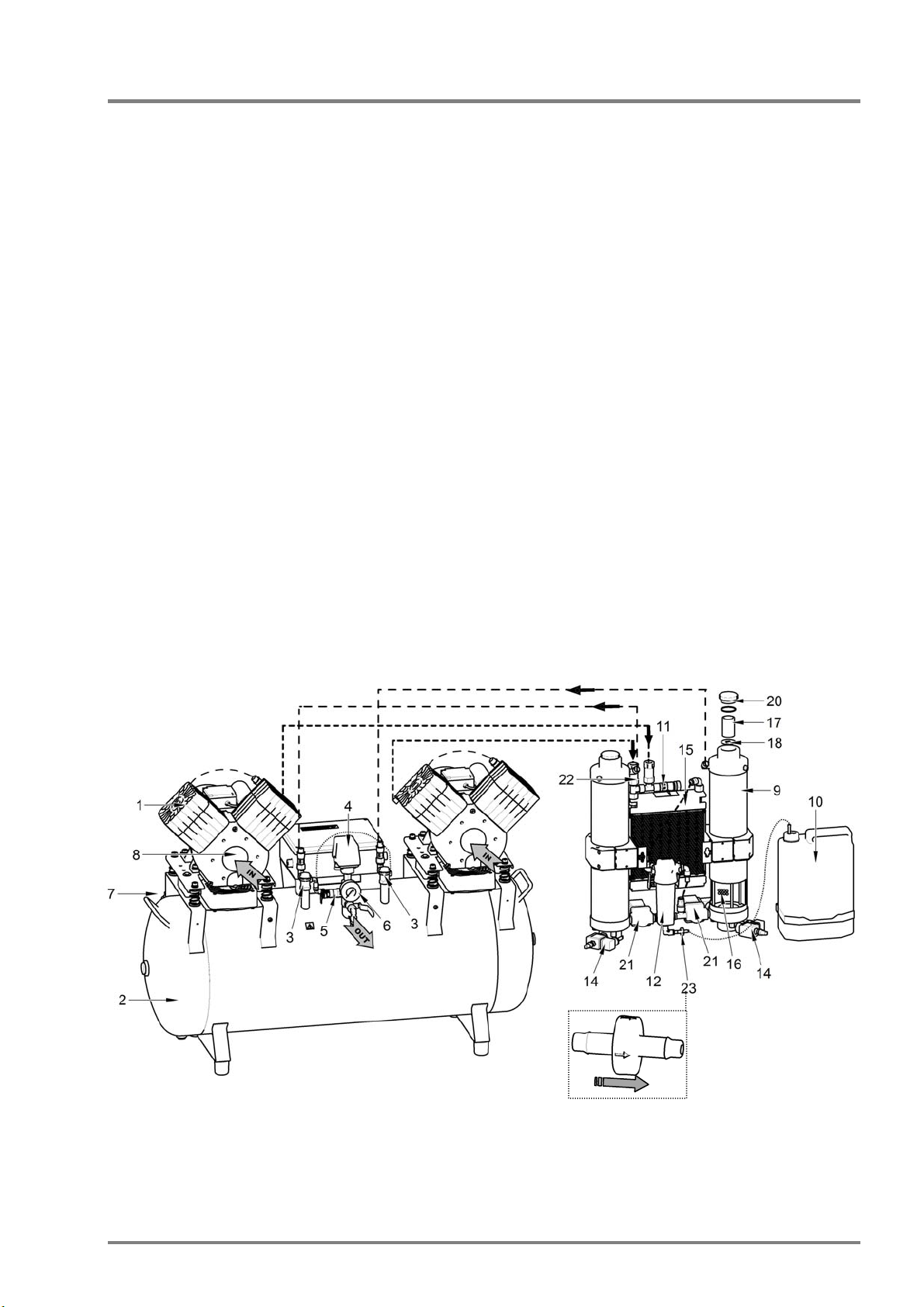
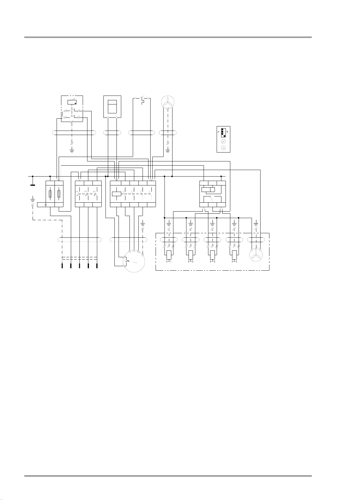
Before connecting the dryer to the air tank used on a compressor without a dryer, the internal surface of
the air tank must be properly cleaned and all condensed liquids must be completely removed. The
electrical portion of the dryer is then to be connected to the compressor following the electrical schematic
pursuant to valid regulations.
Dimensions of the regeneration jets for a dryer
Compressor Jet size switch on
- off pressure
Quantity of dry air
at atmospheric
pressure:
Quantity of regeneration
air:
DK50 2V/110/M2 Ø 0,4 mm 5 – 7 bar 140 l/min. 10 l/min. / 5 bar
DK50 2x2V/110/M2 Ø 0,85 mm 5 – 7 bar 280 l/min. 45 l/min. / 5 bar
DK50 2V/110/M2 Ø 0,4 mm 6 – 8 bar 140 l/min. 11 l/min. / 6 bar
DK50 2x2V/110/M2 Ø 0,85 mm 6 – 8 bar 280 l/min. 50 l/min. / 6 bar
DK50 2V/110/M2 Ø 0,4 mm 8 – 10 bar 140 l/min. 15 l/min. / 8 bar
DK50 2x2V/110/M2 Ø 0,6 mm 8 – 10 bar 280 l/min. 35 l/min. / 8 bar
DK50 2V/50/M3 Ø 0,6 mm 5 - 8 bar 140 l/min. 25 l/min./ 5bar
DK50 2V/50/M3 Ø 0,6 mm 5 - 7 bar 140 l/min. 25 l/min./ 5bar
DK50 2V/50/M3 Ø 0,6 mm 6 - 8 bar 140 l/min. 30 l/min./ 6bar
DK50 2V/50/M3 Ø 0,4 mm 8 - 10 bar 140 l/min. 14 l/min. / 8 bar
DK50 2V/M3 Ø 0,6 mm 5 - 7 bar 140 l/min. 25 l/min./ 5bar
DK50 2V/M3 Ø 0,6 mm 6 - 8 bar 140 l/min. 30 l/min./ 6bar
DK50 4VR/50/M2 Ø 0,85 mm 5 - 8 bar 280 l/min. 50 l/min./ 5bar
MAINTENANCE
7. MAINTENANCE SCHEDULE
Maintenance that must be performed Chapter Time interval Performed by
• Replacement of filter in dryer 8.1 1 x year qualified technician
• Replacement of refill in dryer NI 1 x every 4 years qualified technician
• Replacement of the buoy in the
water separator 8.2 1 x year qualified technician
8. MAINTENANCE
Before proceeding, depressurize the air tank to zero and disconnect the appliance from
the electrical mains!
The equipment has been constructed and produced to keep maintenance to a minimum.
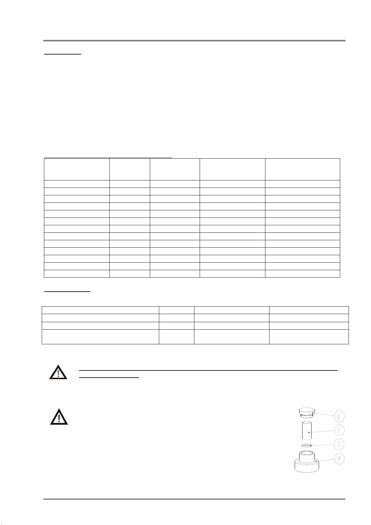
8.1. Replacement of filter in drier
Before proceeding, depressurize the air tank to zero and
disconnect the appliance from the electrical mains.
The dryer filter in the upper section must be replaced during regular dryer
operation or when eliminating a fault caused by contamination.
Remove the dryer plug (1) by unscrewing to the left from the dryer head (4).
Replace the filter (2) and the clean the screen (3).
After removing the screen, check and replace the desiccant in the dryer.
Annex 1 / Technical Instruction – Replacing dryer desiccant/
Refit the dryer plug to the dryer head (4) and tighten it to the right.