eks LCON-R User manual

VERSION: 06/04
TECHNISCHE ÄNDERUNGEN VORBEHALTEN
SUBJECT TO TECHNICAL ALTERATIONS
System LCON-R
Version R2.0
Description and Manual
eks Ralph Engel
Schützenstraße 2
DE-57482 Wenden
Tel: +49 (0) 2762 93136
Fax: +49 (0) 2762 3016
E-Mail: [email protected]
Internet: www.eks-engel.de

Manual
System LCON-R
VERSION: 06/04
TECHNISCHE ÄNDERUNGEN VORBEHALTEN
SUBJECT TO TECHNICAL ALTERATIONS
SEITE : 1
System Description
The interface module LCON operates as a coupler of RS485 two-wired busses with fiber
optic busses. This system especially enables the connection of PROFIBUS-DP or
PROFIBUS-FMS with fiber optics.
It shows that the connection of data processing applications is not easy. If too many units
are connected or too long transmission paths are established, emg-distortion and potential
differences may occur as great problems in a network. The solution is optical data
transmission. Additionally, potential separation is often not achieved.
The LCON-R contains one RS485-channel and two fiber optic channels. Each channel is
connected to the other channels by an electronic circuit. A message that is received on
one channel will be prepared, amplified and overplugged on the two other channels.
The system LCON-R allows to create redundancy topologies with fiber optics. A failure
between two LCON-Rs in an optical ring structure will be detected and signaled with LED’s
and failure relays. The participants are always available as they are connected and
addressed via a line structure. This also applies to a failure of the LCON-R system.

Manual
System LCON-R
VERSION: 06/04
TECHNISCHE ÄNDERUNGEN VORBEHALTEN
SUBJECT TO TECHNICAL ALTERATIONS
SEITE : 2
Safety Instructions
In case of non-observance of these warning instructions, personal injury and material
damage may occur. Appropriate transport, professional storing, assembly and installation
are necessary to ensure faultless and safe operation. In order to mark security relevant
procedures in this manual, the following security notes apply, which are characterised by
the shown pictograms:
This sign means: NOTE!
NOTE marks activities and procedures, which can have important influence
on the adequate operation. In case of non-observance consequential
damage may occur.
This sign means: WARNING!
WARNING refers to activities and procedures that may lead to safety
hazards for persons and goods, if they are not carried out adequately.
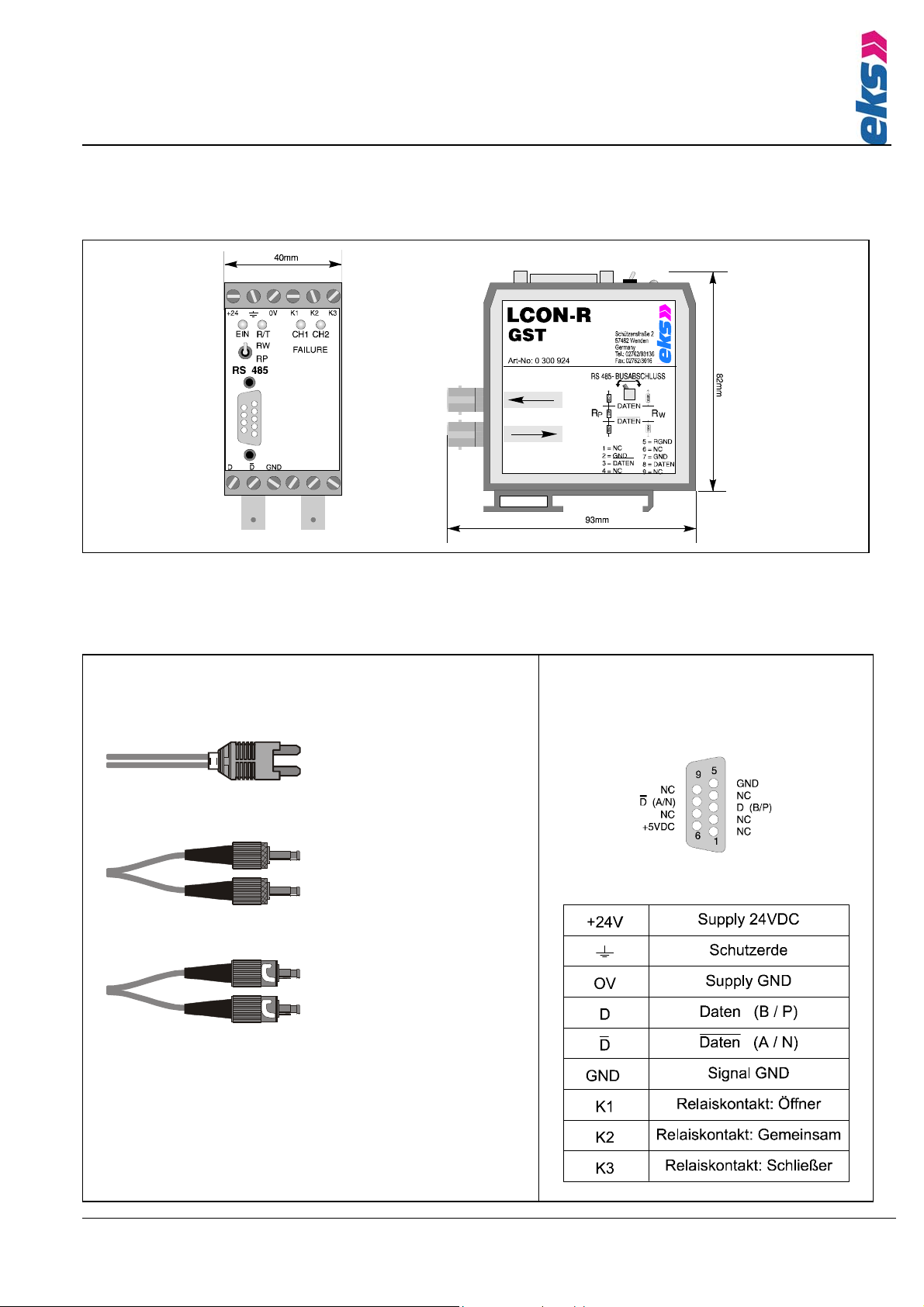
Advice for connections
Supply voltage 24V
Impress the supply voltage of 24DVC on the clamps 24VDC and 0V.
During the operation of electrical equipment and facilities it is inevitable, tha
t
certain parts are under dangerous voltage. Only electronic technicians ma
y
work with electrical equipment and at electrical facilities. Instructed persons,
who are guided and observed by an electric technician may also work in
these surroundings. For both cases applies, that all work has to be done
according to electronical rules and regulations.
Optical connection of fiber optics
Clamp the optical connector in a way, that in each case the right channel o
f
one LCON-R is connected with the next right LCON-R and the left channel
of the LCON-R is connected with the next adjoining LCON-R on the left.
Please note, that it is important to connect always a sender and a receiver.
Pay attention to cleanness! Intruding dust can disable the optical
components. Therefore, remove the protective dust cover imminent before
the optical connection is established.
While in operation, bundled light opts out of the fiber optic senders. Don’
t
stare into the light of the sender!

Manual
System LCON-R
VERSION: 06/04
TECHNISCHE ÄNDERUNGEN VORBEHALTEN
SUBJECT TO TECHNICAL ALTERATIONS
SEITE : 3
Data D and D/
Data can be alternatively withdrawn from the 9pin SUB-D-connector or from the screw
clamps D or D/ . Please note, that there is no conductive connection between GND and
0V.
Failure relay
A failure notice for the optical channel 1 (CH1) can be withdrawn at clamps K1, K2 and
K3 over a potential free two-way contact (Kanalmeldung). For the optical channel 2
(CH2), the failure notice can be withdrawn at clamps K4, K5 and K6 over a potential free
two-way contact (Kanalmeldung). An internal jumper facilitates the output of all failures as
a collective declaration (Sammelmeldung).
Sammelmeldung
Kanalmeldung
Exception: With the type LCON-R/GST/K+P (Order-No. 0300931) it is possible to
withdraw a collective failure declaration at clamps K1, K2 and K3 for optical channel 1
(CH1) or channel 2 (CH2) over a potential free two-way contact.
Green LED “ON“
means that LCON-R is supplied with voltage (24VDC) and that the internal operating
voltage of 5VDC is available.
Yellow LED “R/T“
flickers, if data from the electrical channel (RS485) is transmitted to the optical channels.
Red LEDs “FAILURE CH1 CH2“

Manual
System LCON-R
VERSION: 06/04
TECHNISCHE ÄNDERUNGEN VORBEHALTEN
SUBJECT TO TECHNICAL ALTERATIONS
SEITE : 4
These LEDs shine, if there is no signal reception on the particular optical channel (fiber
optic receiver). This display can be used to check fiber optic connections. If both
receivers of the LCON-R receive signals from the adjoining LCON-Rs, the LED is not
shining. The connection of a participant (master or slave) is not necessary for this. The
clearing takes place approx. 2 seconds after the correct data reception.
Planning of optical rings with LCON-R
• From the software-side a nonexistent participant has to be established
with the maximum possible bus address.
• The value RETRY has to be raised to a minimum of 3.
• The value SLOT TIME has to be adjusted to a minimum of 900.
Advice for laying the fiber optics
Please consider the following points:
• Humidity and rodent protection while choosing the fiber optic.
• Connections are sensitive against contamination. Therefore, protect non required fiber optic
connectors and terminals with the delivered dust protection covers.
• Don’t bend, twist, stretch, overexpand, press or squeeze the fiber optic cable!
• Take the allowed bending radius into account!
• Think of the temperature range!
• Observe the maximum tractive force!
Trouble Shooting
If there occur problems, while establishing the connection, please check the following settings:
• Correct connection between LCON and end device?
• Are the screw clamps tighten?
• Are the fiber optic converters supplied with power?
• Is the right interface chosen?
• Are all optical and electrical parameters considered and adjusted?
• Is the cable bend too strong?
• Is the transmission path too long?

Manual
System LCON-R
VERSION: 06/04
TECHNISCHE ÄNDERUNGEN VORBEHALTEN
SUBJECT TO TECHNICAL ALTERATIONS
SEITE : 5
The following diagramm helps with trouble-shooting:

Manual
System LCON-R
VERSION: 06/04
TECHNISCHE ÄNDERUNGEN VORBEHALTEN
SUBJECT TO TECHNICAL ALTERATIONS
SEITE : 6
Bases of calculation
Following parameters must be strictly adhered to
tRING = < ½ * Slot time
tRING = (n-1)*t LCON-R + l * t fiber optic
tRING = max. delay in the ring
n= number of LCON-R systems in the ring
tLCON-R = module delay: delay of the signals in the LCON-R
l
= length of fiber optics in the ring
tfiber optic = delay per meter fiber optic
The following characteristics apply:
Data rate
in KBit/s
Delay per
LCON-R
Delay per
meter fiber
optic
Slot time
in bit times
Delay in
the ring
max. distance
between two
LCON-R
Expansion in
the ring
1500 4,5 µs 5 ns 900 0,30 ms 0,7 km 120 km
500 4,5 µs 5 ns 900 0,90 ms 2,2 km 360 km
187,5 4,5 µs 5 ns 900 2,40 ms 5,8 km 960 km
93,75 4,5 µs 5 ns 900 4,80 ms 11,7 km 1920 km
45,45 4,5 µs 5 ns 900 9,90 ms 24,2 km 3960 km
19,2 4,5 µs 5 ns 900 23,44 ms 57,2 km 9375 km
9,6 4,5 µs 5 ns 900 46,88 ms 114,5 km 18750 km

Manual
System LCON-R
VERSION: 06/04
TECHNISCHE ÄNDERUNGEN VORBEHALTEN
SUBJECT TO TECHNICAL ALTERATIONS
SEITE : 7
VIEW
Connection Technology
Optical connection
HP - Versatile Link
F - SMA
F - ST
Electrical connection
9 pol. SUB-D female
Screw clamps

Manual
System LCON-R
VERSION: 06/04
TECHNISCHE ÄNDERUNGEN VORBEHALTEN
SUBJECT TO TECHNICAL ALTERATIONS
SEITE : 8
TECHNICAL DATA
LCON-R/GST/K+P LCON-R/GST LCON-R/GSMA LCON-R /KST
Order No. 0 300 931 0 300 930 0 300 925 0 300 929
Fiber connector F-ST F-ST F-SMA F-ST
Data rate max. 100KBit/s 9,6kBit/s, 19,2KBit/s, 93,75KBit/s, 187,5KBit/s, 500KBit/s, 1,5
MBit/s
Fiber Glass Fiber
62,5 (50)/125 µm
POF
980/1000 µm
Optical Budget
typical
Worst Case
8(4,2) dB 12 dB
Transmission path 2600 (1400) m
(3 dB/km)
70 m
(180 dB/km)
Wavelength 820 nm 650 nm
Transmission half duplex
Load switchable: pull-up and wave resistance (Rp) or (Rw)
Cable length 50 m max.
Delay 4,5µs per module and 5ns per meter fiber optic
Bit distortion max. 60 ns
Connector 9 pol. SUB-D female
Control - LED’s Power (green), data (yellow), fiber optic failure (red)
Failure relay potential free relay contact (two-way contact)
Current consumption 100mA at 24VDC
Operating voltage 24 V (18...30 VDC), other voltages on request
Potential separation 500 VDC (24 VDC →RS485)
Operating temperature 0 °C / 70 °C
Weight 250 g
Dimensions H x T x B 82 x 93 x 40 mm
Case Polyamide case, grey, for snap mounting

Manual
System LCON-R
VERSION: 06/04
TECHNISCHE ÄNDERUNGEN VORBEHALTEN
SUBJECT TO TECHNICAL ALTERATIONS
SEITE : 9
APPLICATION
Optical Ring Structure
FFF
IM FAULT
BUS FAULT
POWER ON
24 V
SUB-D9
FFF
IM FAULT
BUS FAULT
POWER ON
24 V
SUB-D9
FFF
IM FAULT
BUS FAULT
POWER ON
24 V
SUB-D9
FFF
IM FAULT
BUS FAULT
POWER ON
24 V
SUB-D9
Table of contents
Other eks Recording Equipment manuals