TEXIO PSF-400H User manual
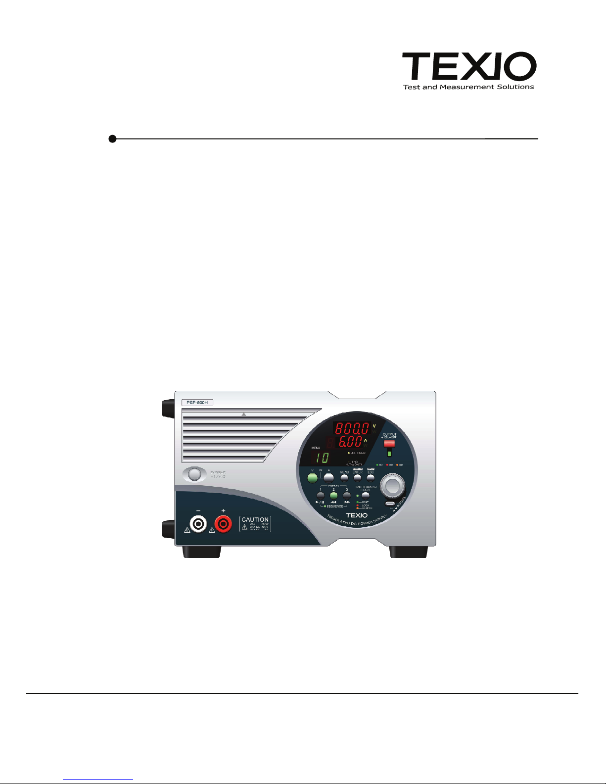
REGULATED DC POWER SUPPLY
PSF SERIES
PSF-400H PSF-800H
©PRINTED IN JAPAN B68-0166-00
INSTRUCTION MANUAL

■ About Brands and Trademarks
Our company and product names described in this manual are the brands and
trademarks owned by the respective companies or organizations in each
country and region.
■ About the Instruction Manual
Permission from the copyright holder is needed to reprint the contents of this
manual, in whole or in part. Be aware that the product specifications and the
contents of this manual are subject to change for the purpose of improvement.

CONTENTS
USING THE PRODUCT SAFELY ................................................................ Ⅰ-Ⅳ
1. GENERAL ____________________________________________ 1
1-1. General ............................................................................................. 1
1-2. Applicable Products .......................................................................... 1
1-3. Features............................................................................................ 1
1-4. Accessories....................................................................................... 3
2. SPECIFICATIONS______________________________________ 4
3 PRELIMINARY INSTRUCTIONS __________________________ 11
4. DEVICES ON PANELS _________________________________ 13
4-1. Front Panel ..................................................................................... 13
4-2. Operation Panel.............................................................................. 14
4-3. Rear Panel...................................................................................... 17
5. OPERATION PROCEDURES ____________________________ 20
5-1. Connecting AC Power Cable .......................................................... 20
5-2. Connecting Load with Output Terminals......................................... 20
5-2-1. Connection with the rear output terminals........................................ 20
5-2-2. Assembling and connecting the front output terminal plug ............... 22
5-3. Operation Ranges........................................................................... 23
5-4. Various Setting................................................................................ 24
5-4-1. How to rotate display panel by 90 degrees............................................. 24
5-4-2. Various Setting ................................................................................. 24
5-4-3. How to set voltage............................................................................ 25
5-4-4. How to set current ............................................................................ 25
5-4-5. How to set power ............................................................................. 25
5-4-6. How to output ................................................................................... 26
5-4-7. How to display the set value in outputting condition......................... 27
5-4-8. How to invalidate on-panel operations (Key lock function)............... 27
5-5. Various Functions Available on Menus ........................................... 28
5-5-1. Preset function (01).......................................................................... 29

5-5-2. OVP/OCP function (02).................................................................... 30
5-5-3. OFF timer function (03) .................................................................... 31
5-5-4. Sequence function (04) .................................................................... 32
5-5-5. External control (external voltage, external resistance) (05) ............ 35
5-5-6. External control (ON/OFF) (06)........................................................ 37
5-5-7. Master-slave function (10)................................................................ 38
5-6. Output Voltage Remote Sensing .................................................... 39
5-7. External Control Functions ............................................................. 40
5-7-1. Output voltage monitor and output current monitor .......................... 41
5-7-2. Set voltage with external voltage or resistance...................................... 42
5-7-3. Set current with external voltage or resistance ...................................... 43
5-7-4. Output ON/OFF with external contacts............................................. 44
5-7-5. Alarm function using external contacts............................................. 44
5-7-6. Various status signals (CV, CC & ALARM)....................................... 45
5-8. Activating output when turning on power........................................ 46
5-9. Usage of sequence Function.......................................................... 46
6 OTHER FUNCTIONS ___________________________________ 48
6-1. Display in alarm status.................................................................... 48
6-2. One-Control Parallel Operation ...................................................... 49
7 OPTION _____________________________________________ 53
7-1. Accessories..................................................................................... 53
7-2. Interface Boards ............................................................................. 53
8 EXTERNAL CONTROL THROUGHT INTERFACE BOARD_____ 54
8-1. Remote control ............................................................................... 54
8-2. Interface connectors ....................................................................... 54
8-3. Specifications.................................................................................. 55
8-3-1. Specifications of IF-60RU ................................................................ 55
8-3-2. Specifications of IF-60GP ................................................................ 56
8-4. Connection Methods....................................................................... 57
8-5. Connection cable ............................................................................ 58
8-6. Address Setting............................................................................... 58
8-7. Using Interface Boards ................................................................... 61
8-7-1. Using the GP-IB interface ................................................................ 61
8-7-2. Using the USB interface................................................................... 61

8-7-3. Using the RS-232C interface ........................................................... 62
8-7-4. Using the local bus........................................................................... 62
8-8. Communication commands ............................................................ 62
8-8-1. Output voltage setting (:VOLT) ........................................................ 64
8-8-2. OVP setting (:VOLT:PROT) ............................................................ 64
8-8-3. Output current setting (:CURR) ....................................................... 64
8-8-4. OCP setting (:CURR:PROT)........................................................... 65
8-8-5. Output power setting (:POW) .......................................................... 65
8-8-6. OUTPUT ON/OFF (:OUTP).............................................................. 66
8-8-7. Display switching (:CONF:DISP)...................................................... 66
8-8-8. External control setting (:EXT:MOD) ................................................ 66
8-8-9. External output voltage controlON/OFF (:EXT:VOLT) ...................... 67
8-8-10. External output current control ON/OFF (:EXT:CURR) .................. 67
8-8-11. OUTPUT switching (:EXT:OUTP) ................................................... 67
8-8-12. Off timer ON/OFF (:TIMER:MOD) .................................................. 68
8-8-13. Off timer value setting (:TIMER:SET)............................................. 68
8-8-14. Monitor inquiry (:MEAS?) ............................................................... 68
8-8-15. Preset calling (:PRES:CALL) ......................................................... 69
8-8-16. Preset saving (:PRES:SAVE) ......................................................... 69
8-8-17. Sequence mode setting (:SEQ:MOD) ............................................ 69
8-8-18. Sequence jump setting (:SEQ:STEP) ............................................ 70
8-8-19. Sequence start step setting (:SEQ:START) ................................... 70
8-8-20. Sequence end step setting (:SEQ:END) ........................................ 70
8-8-21. Sequence repletion frequency setting (:SEQ:CYCL)...................... 71
8-8-22. Sequence data transfer (:SEQ:DOWNLOAD) ................................ 71
8-8-23. Model inquiry (*IDN?) ................................................................. 71
8-8-24. Event register inquiry (*ESR?) ..................................................... 72
8-8-25. Event enable register setting(*ESE)............................................. 72
8-8-26. Status byte inquiry (*STB?) .......................................................... 72
8-8-27. SRQ enable register setting (*SRE)............................................. 72
8-8-28. Buffer clear (*CLS)....................................................................... 72
8-8-29. Communication reset (*RST) ....................................................... 72
8-8-30. Command completion (*OPC)...................................................... 73

8-8-31. Wait for completion (*WAI) ........................................................... 73
8-8-32. Local address setting (:ADDR)....................................................... 73
8-8-33. Remote/local setting (:REMOTE) ................................................... 74
8-9. Registers......................................................................................... 75
8-9-1. Status register (STB、SRE) .............................................................. 76
8-9-2. Event register (ESR、ESE)............................................................... 77
8-9-3. Function of the status byte ............................................................... 78
8-9-4. Reading data from the status byte and clearing the status byte ......... 78
8-9-5. Clear and reset statuses .................................................................. 79
8-9-6. Remote/local function....................................................................... 80
8-9-7. Responses to multi-line message commands.................................. 80
9 TROUBLESHOOTING __________________________________ 81
10 MAINTENANCE ______________________________________ 82
11 OUTSIDE DIMENSIONS _______________________________ 83

I
USING THE PRODUCT SAFELY
■Preface
To use the product safely, read this instruction manual to the end. Make sure
you understand how to correctly use this product before using it.
If you read this manual but you do not understand how to use the product, call
our company or one of our service centers.
Save the instruction manual after you read it so that you can refer to it when
necessary.
■ Pictorial indication and warning character indication
This instruction manual and the product show the warning and caution items
required to safely use the product.
The following pictorial indication and warning character indication are provided.
<Pictorial indication>
Some parts of this product or certain sections of the
instruction manual may show this pictorial indication.
In this case, if that part of the product is used incorrectly,
the user’s body or the product may be exposed to serious
danger.
Be sure to refer to this instruction manual when using parts
with this pictorial indication.
If you ignore this indication and incorrectly use the product,
you may be killed or seriously injured. This indication
means that a warning item is provided in order to avoid
extreme risk.
If you ignore this indication and incorrectly use the product,
you may suffer slight injury or the product may be
damaged. This indication means that a caution item is
provided in order to avoid risk.
Our company will assume no responsibility for any damage resulting from the
misuse of the product by the user or a third party, a failure or other trouble that
occurs during operation, or the general use of the product, except for cases
where our company is legally liable for the damage

II
USING THE PRODUCT SAFELY
■Do not remove the product's covers and panels
Never remove the product's covers and panels for any purpose.
Doing so may expose the user to electric shock, or result in a fire.
■Caution on using the product
The warning items below are given to avoid danger to the user's body and life,
and to prevent the damage and deterioration of the product.
Observe the following warning and caution items as you use the product.
■Warning items on power supply
●Power supply voltage
The applicable rated source voltage for this product is from 100VAC to 240VAC
or 230ACV.
For the rated voltage of each respective product, see the indication on the
rear panel of the product or the "SPECIFICATIONS" in this instruction manual.
Products for Japan and for regions of commercial power supply voltage up to
125VAC are supplied with a 125VAC rated power cable. However, this cable
may need to be replaced with a different AC power cable when using the
product on source voltage over 125VAC. Using the product on a high voltage
that exceeds 125VAC without replacing the power cable may result in electric
shock or fire. For products that can switch between source-voltages, see
the chapter about switching the source voltage in the instruction manual
included with each respective product for details.
●Power cable
Important: The attached power cable can only be used for this product.
If the attached power cable is damaged, stop using it immediately and
contact our company or one of our service centers. Continuing to use the
damaged power cable may result in electric shock or fire.
●Protection fuse
If the input protection fuse is blown, the product will not operate. For
products equipped with an external fuse holder, the fuse can be replaced.
See the section about fuse replacement in this manual for details.
If no means of replacing the fuse is available to the user, it cannot be replaced.
If the fuse is blown, do not open the case. Contact our company or one of our
service centers and request to have the fuse replaced by one of our
representatives. Incorrectly replacing the fuse may result in electric shock or
fire.

III
USING THE PRODUCT SAFELY
■Warning about grounding
If the product is equipped with a GND terminal on the front or rear panel, be
sure to connect a ground wire to the GND terminal to ensure safe operation.
■Warning about installation conditions
●Operating Temperature and Humidity
Use the product within the operating temperature range described in the
“SPECIFICATIONS”. Do not use the product with the vent holes blocked or in
a high ambient temperature. Failure to heed this warning may result in fire.
Use the product within the operating humidity range described in the
“SPECIFICATIONS”. When moving the product to a room with a different
humidity, pay attention to dew condensation caused by a sudden humidity.
Also, do not handle or operate the product with wet hands. Failure to heed to
this warning may result in electric shock or fire.
●Using Product Near Gases
Do not use the product in or around a place where combustible gas,
explosive gas, or vapor is produced or stored. Failure to heed this warning
may result in explosion or fire.
Do not use the product in or around a place where corrosive gas is produced
or accumulated. Failure to heed this warning may result in serious damage
to the product.
●Installation Place
Do not install the product on an inclined surface or in a place subject to
vibration. Otherwise, the product may fall down or tip over, resulting in
damage or an injury
■Do not allow foreign objects to enter the product
Do not insert metal or flammable materials through the vent and into the
product. Do not spill water on the product.
■Warning about errors during operation
If the product emits smoke, fire, unusual odors, or abnormal noise while in use,
stop using the product immediately. Turn off the switch and disconnect the
power cable from the AC outlet to cut off the electric power supply. Contact
our company or one of our service centers.

IV
USING THE PRODUCT SAFELY
■Input/output Terminal
Maximum input to the input terminals is specified to prevent the product from
being damaged. Do not supply input, exceeding the specifications that are
indicated in the "SPECIFICATIONS" section of this manual. Also, do not
supply power to the output terminals from the outside. Failure to heed this
warning may cause the product to fail.
■Calibration
The performance and specifications of the product were inspected under strict
quality control before shipment. However, the aging of the parts may cause the
performance and the specifications to change. To ensure the performance
and specifications of the product remain unchanged, we recommend that you
have the product calibrated periodically. For calibration, please contact our
company or one of our service centers.
■Daily Maintenance
Do not use thinner, benzine or other solvents to clean the case, panels, knobs,
etc. of the product. Doing so may cause the coating to peel off or the resin
surface to deteriorate.
Use soft cloth moistened with neutral detergent to lightly clean the case, panels,
knobs, and other parts.
While cleaning, be careful not to let water, detergent, or other foreign materials
into the product. If a liquid or metal gets into the product, electric shock or fire
may occur.
Before cleaning the product, make sure to disconnect the power cable from the
AC outlet to cut off the electric power supply.
Use the product correctly and safely, observing the above warning and caution
items. This manual indicates caution items in each individual section. Observe
these caution items to correctly use the product.
If you have questions or comments about the content of this manual, contact our
company or one of our service centers.
1
1. GENERAL
1-1. General
The PSF Series is a variable output type high-performance switching DC
stabilized power supply unit. It incorporates a high-frequency current suppression
circuit and is applicable to the rated source voltage from AC100V to 240V without
the need of switching. It offers wide-range voltage and current outputs within
the maximum rated power range. It also has a variable constant power function.
It has such standard features as voltage and current setting, output On/Off,
monitor output and other functions through external connectors. The frame
depth is smaller than the traditional models for saving the installation space and
providing a wider work space. The PSF Series is able to execute sequence
programs, which are written in it using the optional interface board in advance,
without anything else.
It is possible to control the PSF Series from a Personal computer through the
optional GP-IB, RS-232C or USB interface board.
The application software exclusive for the PSF series may be downloaded
from our homepage.
Homepage address – http://www.texio.jp
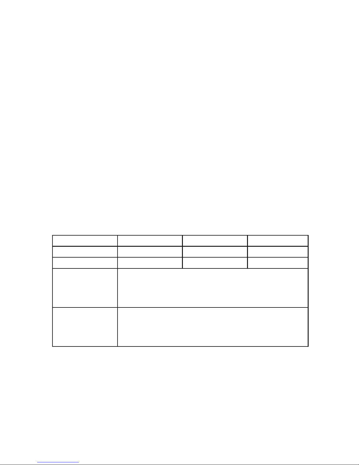
1-2. Applicable Products
Product name Voltage range Current range Power range
PSF-400H 0V to 800V 0A to 3A 0W to 400W
PSF-800H 0V to 800V 0A to 6A 0W to 800W
IF-60GP
(GP-IB)
◆Optional GP-IB interface board
For details of functions, see “8 EXTERNAL CONTROL
THROUGHT INTERFACE BOARD” in this instruction
manual.
IF-60RU
(RS-232、USB)
◆Optional RS-232C and USB interface board
For details of functions, see “8 EXTERNAL CONTROL
THROUGHT INTERFACE BOARD” in this instruction
manual.
1-3. Features
●Flexible range Output
Capable of wide-range voltage and current setting within the rated power range.
●Constant-Power Control
Provides constant-power (CP) control in addition to constant-voltage (CV) and
constant-current (CC) controls.
●Power Factor Correction Circuit

2
A built-in power factor correction circuit ensures compatibility to a wide AC
input voltage range from AC100V to 240V without the need of switching.
It also suppresses harmonic current.
●Rotary Panel Operation Unit
The panel operation unit may be rotated by 90 degrees for easy-to-see
monitoring in either horizontal or vertical installation.
●Off Timer Function
Turns off output automatically after a lapse of preset time in order to prevent
“a failure to turn off output” or “over-charging” even in the case where the
user does any other work without turning it off.
●Sequence (SEQ) Function
Executes data read from a Personal computer through the optional interface
board on the panel operation unit. Two operation modes are available:
Manual mode (for execution while checking the step details), and automatic
mode (for automatic execution of steps). (100 steps, 999 cycles)
●Protective Functions
Has internally fixed protective functions, which are OVP, OCP and OHP.
Also has OVP and OCP functions, which may be set on the panel operation
unit.
●Preset Functions (Three Points)
Pressing a preset key directly selects a preset value, which is set in advance.
●One Control Operation
Provides master-slave one control operations.
●External Control Function
Offers voltage- and resistance-based controls, voltage monitoring, current
monitoring, output On/Off, alarm, CV/CC status and other functions as the
standard features.

3
●Options
Two types of optional boards, GP-IB + local bus board and RS-232C + USB
+ local bus board, are available for applications with several built-in units,
which are operated simultaneously in a factory, etc.
It is possible to store sequence programs and read voltage and current data
if application software is created.
●Space Saving Design
The frame depth is shorter than our other products for easy installation on a
desk or other small space.
1-4. Accessories
Make sure the accessories are attached correctly.
If there are any problems,pleasw contact one of our sales branches.
(1) Instruction manual (this printing)
(2) Front output terminal plugs (one red pair, one white pair)
(3) External control connector (26-pin)
(4) Semi covers for external control connector (2 pcs)
(5) Output ground cable
(6) Screws (for attaching the output ground cable)
(7) AC power cable

4
2. SPECIFICATIONS
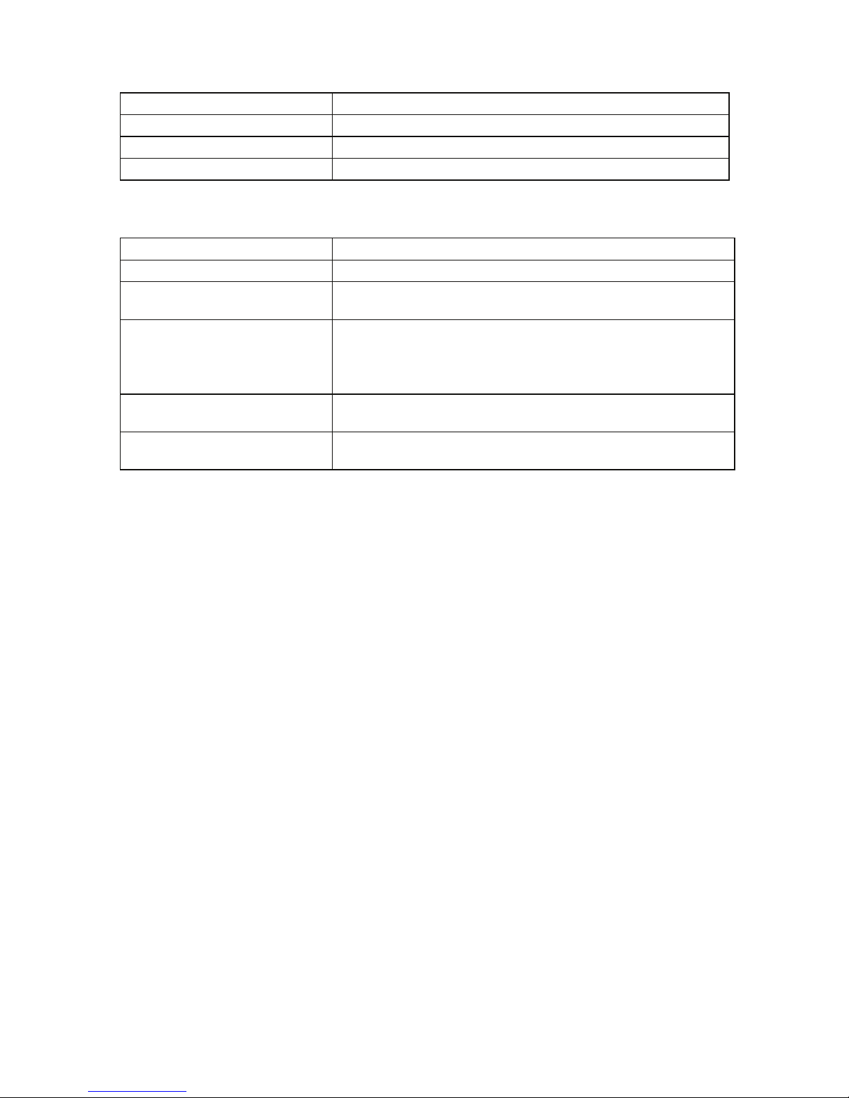
●Output Specifications
Model PSF-400H PSF-800H
Rated output voltage 800.0V
Setting accuracy 0.1%setting±2digit (23°C±5°C)
Resolution 100mV
Display accuracy 0.2%reading±2digit (23°C±5°C)
Rated output current ※13.00A 6.00A
Setting accuracy 0.2%setting±2digit (23°C±5°C)
Resolution 10mA
Display accuracy 0.3%reading±2digit (23°C±5°C)
Rated output power ※2400W 800W
Setting accuracy ±10W.
Output voltage should be at least 1% of the rated voltage
Resolution 10W
Display accuracy 0.5%reading±Vout×40mA (23°C±5°C)
※1: The maximum output current through the front output terminals is 3A(400H)、or
6A(800H).
※2: Switching from the constant-voltage (CV) or constant-current (CC) mode into
the constant-power (CP) mode or vice versa is subject to over-shoot ringing, etc.
●Input Specifications
Model PSF-400H PSF-800H
Input voltage AC100V to 240V, single-phase, frequency: 50Hz or 60Hz
Power consumption ※3560VA 1120VA
Power factor ※40.99
Rush current 35Amax. 70Amax.
※3, 4: At the rated output voltage and AC100V input
●Constant-Voltage Characteristics
PSF-400H PSF-800H
Source fluctuation ※50.01% ±20mV of rated voltage
Load fluctuation ※60.01% ±30mV of rated voltage
250mV 300mV
Ripple noise (p-p) ※7Output voltage should be at least 1% of the rated voltage
20mV
(When current is 2A or lower)
25mV
(When current is 2A or lower)
35mV
(When current is higher than 2A)
40mV
(When current is higher than 2A)
Ripple noise (rms)※8
Output voltage should be at
least 1% of the rated voltage
Transient response (typ.)※97ms
Rise time (typ.)※10 200ms(rated load) 200ms(no load)
Fall time (typ.)※11 500ms(rated load) 1000ms(no load)
Temperature coefficient (typ.)※12 ±100ppm/°C(after 30-minute warming up)

5
●Constant-Current Characteristics
PSF-400H PSF-800H
Source fluctuation ※50.05%±10mA of rated current
Load fluctuation ※13 0.05%±15mA of rated current
Ripple noise (rms) 15mA 20mA
Temperature coefficient (typ.)※12 ±200ppm/°C(after 30-minute warming up)
●Constant-Power Characteristics
PSF-400H PSF-800H
Source fluctuation※50.5%±10W
※5: Fluctuation when the source voltage is changed by ±10% in the range from AC100V to
240V.
※6: Fluctuation when the load is changed from the rated load into no load (open circuit) at the
rated output voltage.
※7: Measured at the frequency up to 20 MHz.
※8: Measured at the frequency up to 300kHz.
※9: Response time till the output voltage is restored to the range within 0.1% + 10 mV of the
rated output voltage when the output current is changed from 50% to 100% of the
maximum output current at the rated output voltage.
※10: Value with a fixed load.
Time until the output voltage increases up to 10% to 90% of the rated output voltage.
※11: Value with a fixed load.
Time until the output voltage decreases down to 90% to 10% of the rated output voltage.
※12: Value after 30 minutes of warming up (excluding external control).
※13: Fluctuation when the load is changed from the rated load into no load (short circuit) at the
rated output current.

6
●Functions
Constant-voltage (CV)
control with external voltage
Output voltage: Approx. 0V to 800V
for external voltage: 0V to 10V
Constant-voltage (CC) control
with external resistance
Output voltage: Approx. 0V to 800V
for external resistance: 0Ωto 10KΩ
Constant-current (CC) control
with external voltage
Output current: Approx. 0A to 3A (400H) or 0A to 6A (800H)
for external voltage: 0V to 10V
Constant-current (CC) control
with external resistance
Output current: Approx. 0A to 3A (400H) or 0A to 6A (800H)
for external resistance: 0Ωto 10kΩ
External On/Off control On/Off at contact, short: On, open: Off
Output voltage monitor signal Approx. 0V to 10V for 0V to 800V output voltage.
Output current monitor signal Approx. 0V to 10V for 0A to 3A(400H) or 0A to 6A(800H)
output current.
Constant-voltage (CV)
status signal Open collector, active Low.
Constant-current (CC)
status signal Open collector, active Low.
Alarm signal output Open collector, active Low.
Alarm signal input Turns off output when shorted.
Remote sensing function Compensates for voltage drop up to 1V (single side). Within
rated voltage at both ends of power supply.
Parallel one-control operation Up to two units
Preset function A maximum of three points are presettable.
Off timer (OFF TIMER)
function
Time until turning off output is presettable.
Setting range: 10min. to 99hrs. & 50min.
Key lock function Disables operations on front panel.
Sequence function
Number of steps: 0 to 99
Step time: 1 to 9999 (sec.)
Number of cycles: 1 to 999 (--: Infinite)
The product is capable of simple program operations using the
exclusive application software.
The application software exclusive for sequence operation may
be downloaded from our homepage.
●Protective functions
Over-voltage protection
(OVP): Fixed ※14
Output Off when output voltage exceeds 110% of rated
voltage.
Over-voltage protection
(OVP): Variable ※15
Presettable in range from 10V to 840V on front panel.
Output Off when OVP works.
Over-current protection
(OCP): Fixed ※14
Output Off when output current exceeds 110% of rated
current.
Over-current protection
(OCP): Variable ※15
Presettable in range from 0.1A to 3.15A(400H) or 0.1A to
6.30A(800H) on front panel.
Output Off when OCP works.
Overheat protection (OHP)※14 Output Off at the internal heat sink
temperature over the set temperature.
※14: Throw the POWER switch again to reset.
※15: Throw the POWER switch again or press the ESC key to reset.
7
●Environmental Conditions
Operating temperature range 0ºC to +40ºC
Operating humidity range 30% RH to 80% RH (No dew condensation)
Storage temperature range -20ºC to +70ºC
Storage humidity range 30% RH to 80% RH (No dew condensation)
●Others
Cooling method Forced cooling with fan motor
To-GND voltage ±DC1000V
Dielectric strength voltage Power In terminals - frame: AC1500V, 1min.
Power In terminals - output terminals: AC2300V, 1min.
Insulation resistance
Power In terminals - frame: DC500V, 30MΩor more
Power In terminals - output terminals:
DC1000V, 30MΩor more
Output terminals - frame: DC1000V, 30MΩor more
Outside dimensions
(Projections not included.) 124(H)mm×210(W)mm×290mm(D)
Weight PSF-400H: Approx. 5kg
PSF-800H: Approx. 6kg

8
●One-Control Operation Setting Table
PSF-400H
Single Parallel connection
400H 400H×2
Item
400W 800W
SLOW 100mV
FAST 10V
Range 0V to 820V
Voltage setting
Min. display digit 100mV
SLOW 10mA 100mA
FAST 1A 1A
Range 0A to 3.07A 0A to 6.1A
Current setting
Min. display digit 10mA
SLOW 10W 20W
FAST 100W 200W
Range 10W to 410W 20W to 820W
Power setting
Min. display digit 1W
SLOW 1V
FAST 100V
Range 10V to 840V
OVP setting
Min. display digit 100mV
SLOW 10mA 20mA
FAST 1A 2A
Range 0.1A to 3.15A 0.2A to 6.3A
OCP setting
Min. display digit 10mA 10mA
In parallel connection, the minimum digit of current display is 100mA.
In some model combinations, the resolution of current setting is different from the minimum
digit of current display and the display may not be changed by clicking the mouse button
once.

9
PSF-800H
Single parallel connection
800H 800H×2
Item
800W 1600W
SLOW 100mV
FAST 10V
Range 0V to 820V
Voltage setting
Min. display digit 100mV
SLOW 10mA 100mA
FAST 1A 1A
Range 0A to 6.15A 0A to 12.3A
Current setting
Min. display digit 10mA 100mA
SLOW 10W 20W
FAST 100W 200W
Range 10W to 820W 20W to 1640W
Power setting
Min. display digit 1W
SLOW 1V
FAST 100V
Range 10V to 840V
OVP setting
Min. display digit 100mV
SLOW 10mA 20mA
FAST 1A 2A
Range 0.1A to 6.3A 0.2A to 12.6A
OCP setting
Min. display digit 10mA 10mA
In parallel connection, the minimum digit of current display is 100mA.
In some model combinations, the resolution of current setting is different from the minimum
digit of current display and the display may not be changed by clicking the mouse button
once.

10
●Default Setting and Storage after Power Off
Default Setting List of PSF Series
Item Initial setting(400H/800H) Storage after
power off
Voltage 0.0V ○
Current 0.00A ○
Power 410W/820W ○
OVP 840.0V ○
OCP 3.15A/6.30A ○
Display mode V/A ○
Menu display Initialized when power is turned off. ×
Operation mode V ○
External voltage control OFF ○
External resistance control OFF ○
External output on/off IN ○
Preset function OFF ○
Preset item: Voltage 0V ○
Preset item: Current 0A ○
Preset item: Power 410W/820W ○
Off-timer function OFF ○
Sequence function OFF ○
Sequence start No. 0 ○
Sequence end No. 99 ○
Sequence repetition frequency 1 ○
Sequence item: Voltage 0V ○
Sequence item: Current 3.07A/6.15A ○
Sequence item: Power 410W/820W ○
Sequence item: Output OFF ○
Sequence item: Time 1 秒○
Key lock function OFF ×
One-control operation OFF ○
Output status Initialized when power is turned off. ×
Sequence operation status ×(Stop status) ×
Off-timer operation status ×(Non operating status) ×
System address 1 ○
Personal computer address 3 ○
This manual suits for next models
1
Table of contents
Other TEXIO Power Supply manuals

TEXIO
TEXIO PW8-3AQP User manual

TEXIO
TEXIO PFR-100 SERIES Owner's manual

TEXIO
TEXIO PSF-1200L User manual

TEXIO
TEXIO PU6-200 User manual

TEXIO
TEXIO PBW Series User manual

TEXIO
TEXIO PR-A Series User manual

TEXIO
TEXIO PD18-10AD User manual

TEXIO
TEXIO PSW Series User manual

TEXIO
TEXIO PA10-5B User manual

TEXIO
TEXIO PAR-A Series User manual


