manuals.online logo
Brands
  1. Home
  2. •
  3. Brands
  4. •
  5. ekwb
  6. •
  7. Accessories
  8. •
  9. ekwb EK-Vector Strix RTX 2070 RGB User manual

ekwb EK-Vector Strix RTX 2070 RGB User manual

All disclosures, notices and warranty conditions are being written on the EKWB website. Please read terms of use. Released on 1st of March, 2018; Revision 1.0
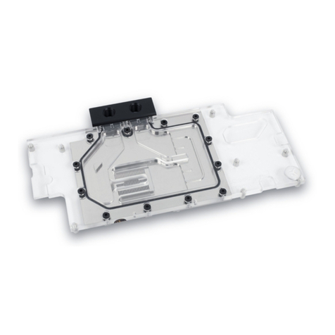
Installation manual EK-Vector Strix RTX 2070 RGB water block
This product is intended for installation only by expert users. Please consult with a
qualified technician for installation. Improper installation may result in damage to your
equipment. EK Water Blocks assumes no liability whatsoever, expressed or implied, for
the use of these products, nor their installation. The following instructions are subject
to change without notice. Please visit our web site at www.ekwb.com for updates.
Before installation of this product please read important notice, disclosure and
warranty conditions printed on the back of the box.
Before you start using this product please follow these basic guidelines:
1. Please carefully read the manual before through before beginning with
the installation process!
2. Please remove your Graphics card from the computer to assure safest
mounting process in order to prevent any possible damages to your GPU
and/or graphics card circuit board (PCB).
3. The EK-HFB and EK-ACF type fittings require only a small amount of
force to screw them firmly in place since the liquid seal is ensured by the
rubber O-ring gaskets.
4. The use of corrosion inhibiting coolants is always recommended for any
liquid cooling system.
BAG CONTENT: Bag content is universal for all water blocks, you may not need all screws.
STEP 1: PREPARING YOUR GRAPHIC CARD
STEP 1 cont: PREPARING YOUR GRAPHICS CARD.
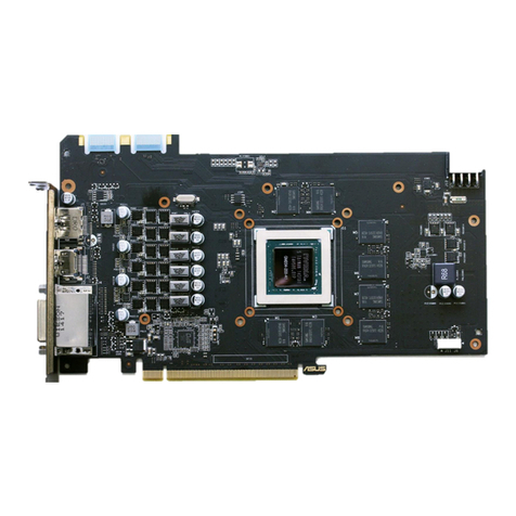
1. REMOVING STOCK COOLER: Remove all encircled screws. All heat sink assembly screws should
be removed, including self-adhesive washers on both sides of the PCB (if present). Also remove encircled
screws on the IO bracket using Phillips screwdriver. After you remove the housing do not forget to unplug
the fan and RGB LED panel.
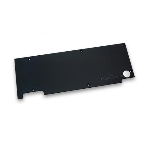
2. REMOVING FACTORY PROVIDED BACKPLATE: Remove all encircled screws using Philips
screwdriver. All heat sink assembly screws should be removed, including self-adhesive washers on both sides of
the PCB (if present).
STEP 1 cont.: PREPARING YOUR GRAPHIC CARD
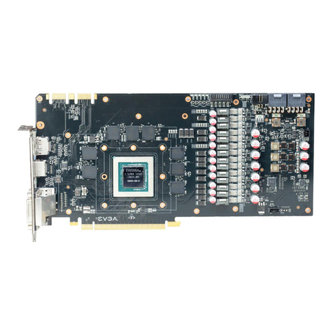
1. CLEANING THE PCB: Carefully detach the original stock cooler after removing all screws securing
it to the board. Wipe off the remains (by using non–abrasive cloth or
q-tip
, as shown on sample photo) of
the original thermal compound until the components and circuit board are completely clean. EKWB
recommends the use of denatured alcohol for removing TIM leftovers.
2. APPLYING THERMAL COMPOUND: Apply thermal compound: lightly coat
NVIDIA
GPU chip with
enclosed EK-TIM Ectotherm thermal grease. EKWB recommends blob or line method of applying the enclosed
thermal compound for best performance (see sample picture)
3. CUTTING THERMAL PADS: Your block comes with thermal pads, some of which are already pre-
cut. Others have to be cut to smaller chunks in order to cover all the VRM components such as MOSFETs,
IC memory and coils. PLEASE REMOVE THE PROTECTIVE FOIL FROM BOTH SIDES OF THE THERMAL
PADS PRIOR TO INSTALLATION.
Replacement thermal pads:
Thermal Pad E –0.5mm (RAM 8x) –(EAN: 3830046996688)
Thermal Pad F –1mm (120x16mm) –(EAN: 3830046996732)
Thermal Pad F –0.5mm (120x16mm) –(EAN: 3830046996732)
4. PLACING THERMAL PADS ON PCB. Place thermal pads on the circuit board as shown on the picture
below. Refer to numbering in previous picture when applying thermal pads of different sizes or thicknesses. EK
made sure to provide customers with more than adequate quantity of thermal pads to complete this step.
1: 2xThermal pad E –
0.5mm(for memory IC):
1
1
1
1
1
1
1
1
2
2: Thermal pad F –1mm
(for Mosfet):
3: 2x Thermal pad F –
0.5mm
(for COILs):
3
1
1
1
1
2
3
1
1
1
1
1
1
1
1
Remove two screws on the IO
bracket using Phillips screwdriver
All disclosures, notices and warranty conditions are being written on the EKWB website. Please read terms of use. Released on 1st of March, 2018; Revision 1.0
STEP 2: INSTALLING THE WATER BLOCK
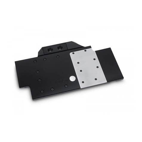
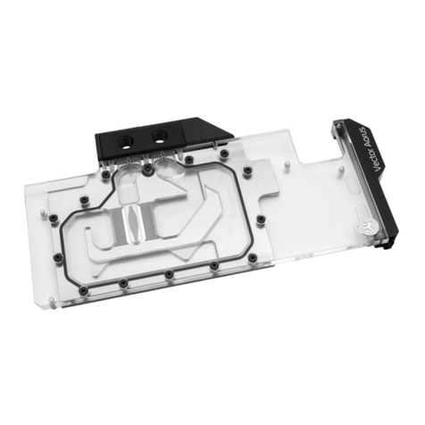
1. PLACING THE BLOCK ON TO THE GRAPHICS CARD. Carefully position the water block with
preinstalled standoffs on to the graphics card. During this process please make sure you align mounting
holes on the PCB with holes on the water block (same applies for other tops). Also pay attention not to use
too much force by pressing the block down to the PCB. Chip dies are prone to cracking.
2. ATTACHING THE BLOCK TO THE GRAPHIC CARD. Use a Philips screwdriver screw with the
enclosed M2,5x4 AX1 screws. EKWB recommends users to start tightening the screws around the GPU core
and continue outwards. Always use a plastic washer under each and every screw! If the washer is already
present on the circuit board (usually around the four GPU core screw holes) there is no need for additional
washer.
STEP 3: CHECKING FOR CONTACTS
If necessary temporarily r
emove the water block to check for uniform surface contact between the block and the components, pay special attention to the VRM section of the
graphics card. Check whether the water block makes contact with the intended integrated circuit. Then repeat sub-steps in previous section to re-attach the block. In case you
fail to obtain good contact, please check again that your thermal pad thickness or contact our support service at http://www.ekwb.com/support.
STEP 4: INSTALLATION OF FITTINGS AND TUBING
Screw in the two G1/4 threaded male fittings. Attach the liquid cooling tubes and connect the water-block(s) into the cooling circuit. EKWB recommends using EK-ACF
fittings with the EK-Vector Strix RTX 2070 RGB series water blocks. To ensure that the tubes are securely attached to the barb/fittings, please use hose clamps or an
appropriate substitute.
0
You can use any opening as an inlet/outlet port. Do not forget to plug the remaining two opening with enclosed EK-Plug G1/4 or equivalent.
CAUTION: In case of using connectors other than EK-ACF series compression fittings, take special attention to the length of the fittings’ male G1/4” thread. 5mm is the maximum
allowed G1/4” thread length!
STEP 5: INSERTING THE CARD IN YOUR PC CASE
Carefully lift your graphics card with installed block and insert it in your PC’s motherboard PCI-express expansion slot. Please bear in mind that your graphics card is probably
heavier than when it was equipped with original heat sink fan assembly. One needs to be very careful when handling the graphics card. Avoid all un-needed manipulation of the
VGA/water block assembly that might damage your card or water block during final installation.
STEP 6: CONNECTING THE RGB LED STRIP
Plastic washer
Screw M2.5x4 AX1
Plug the 4-pin connector from Water block’s RGB LED
light to the RGB_HEADER on the motherboard. The
LED will work if the pin layout on the header is as
follows:
+12V G R B
.
Please ensure that the arrow indicated on
the connector is plugged into the +12V line
as indicated on your motherboard.
Failure to do so will damage your motherboard or LED
strip.
RGB LED Connector
All disclosures, notices and warranty conditions are being written on the EKWB website. Please read terms of use. Released on 1st of March, 2018; Revision 1.0
Another option is to connect RGB_HEADER to the graphic card. If you choose this option, make sure to connect RGB_HEADER before you install water block to the graphic card
(before step 2). Align RGB connector and RGB cable along with the groove (see pictures below). The LED will work if the pin layout on the header is as follows:
+12V G R B
.
Please ensure that the triangle indicated on the connector is plugged into the +12V line as indicated on your graphic card.
Failure to do so will damage your graphic card or LED strip.
REQUIRED TOOLS:
scissors Philips head screwdriver

Other ekwb Accessories manuals

ekwb EK-FB ASUS Maximus XI EXTREME User manual

ekwb

ekwb EK-FB ASUS Maximus XI EXTREME User manual

ekwb EK-FB MSI X470 M7 RGB User manual

ekwb

ekwb EK-FB MSI X470 M7 RGB User manual

ekwb EK-FC970 GTX Strix Backplate Guide

ekwb

ekwb EK-FC970 GTX Strix Backplate Guide

ekwb EK-FC1070/1080 GTX User manual

ekwb

ekwb EK-FC1070/1080 GTX User manual

ekwb EK-FC980 GTX Classy Backplate Guide

ekwb

ekwb EK-FC980 GTX Classy Backplate Guide

ekwb EK-FC1080 GTX Strix User manual

ekwb

ekwb EK-FC1080 GTX Strix User manual

ekwb EK-FB ASRock X470 Gaming K4 RGB User manual

ekwb

ekwb EK-FB ASRock X470 Gaming K4 RGB User manual

ekwb EK-FC1080 GTX Ti FTW3 User manual

ekwb

ekwb EK-FC1080 GTX Ti FTW3 User manual

ekwb EK-FB ASUS Z 170S Monoblock User manual

ekwb

ekwb EK-FB ASUS Z 170S Monoblock User manual

ekwb EK-FB ASUS Z270/Z370 Strix Monoblock User manual

ekwb

ekwb EK-FB ASUS Z270/Z370 Strix Monoblock User manual

ekwb EK-FC1080 GTX Ti Strix RGB User manual

ekwb

ekwb EK-FC1080 GTX Ti Strix RGB User manual

ekwb EK-FC Radeon Pro Duo Guide

ekwb

ekwb EK-FC Radeon Pro Duo Guide

ekwb EK-FB ASUS X99 Monoblock User manual

ekwb

ekwb EK-FB ASUS X99 Monoblock User manual

ekwb EK-FB ASUS CROSSHAIR V Guide

ekwb

ekwb EK-FB ASUS CROSSHAIR V Guide

ekwb EK-FC1080 GTX Ti TF6 User manual

ekwb

ekwb EK-FC1080 GTX Ti TF6 User manual

ekwb EK-Quantum Vector Aorus RTX 2080 D-RGB User manual

ekwb

ekwb EK-Quantum Vector Aorus RTX 2080 D-RGB User manual

ekwb EK-FC980 GTX Classy Backplate Guide

ekwb

ekwb EK-FC980 GTX Classy Backplate Guide

ekwb EK-FC970 GTX TFX Backplate Guide

ekwb

ekwb EK-FC970 GTX TFX Backplate Guide

ekwb EK-FC GV100 PRO User manual

ekwb

ekwb EK-FC GV100 PRO User manual

ekwb EK-DCP 4.0 X-RES Guide

ekwb

ekwb EK-DCP 4.0 X-RES Guide

ekwb EK-FB MSI X299M GAMING PRO CARBON RGB... User manual

ekwb

ekwb EK-FB MSI X299M GAMING PRO CARBON RGB... User manual

ekwb EK-FC R9-290X Backplate Manual

ekwb

ekwb EK-FC R9-290X Backplate Manual

ekwb EK-FB MSI Z170A XPower Te Monoblock User manual

ekwb

ekwb EK-FB MSI Z170A XPower Te Monoblock User manual

ekwb EK-FB KIT GA-X99 Manual

ekwb

ekwb EK-FB KIT GA-X99 Manual

Popular Accessories manuals by other brands

Drum HYDRAPAK Installation operating & maintenance manual

Drum

Drum HYDRAPAK Installation operating & maintenance manual

Somogyi Home AD 500 instruction manual

Somogyi

Somogyi Home AD 500 instruction manual

IFM KI0058 operating instructions

IFM

IFM KI0058 operating instructions

RME Audio Fireface UFX user guide

RME Audio

RME Audio Fireface UFX user guide

elobau 470 EFR 2D1 2K quick start guide

elobau

elobau 470 EFR 2D1 2K quick start guide

Beurer UB 85 Instructions for use

Beurer

Beurer UB 85 Instructions for use

SICK SIM2000 operating instructions

SICK

SICK SIM2000 operating instructions

Leuze electronic Line Profile Sensor Technical description

Leuze electronic

Leuze electronic Line Profile Sensor Technical description

Panasonic WV-TW310S quick start guide

Panasonic

Panasonic WV-TW310S quick start guide

UFESA FLEXY-HEAT BM instruction manual

UFESA

UFESA FLEXY-HEAT BM instruction manual

Fife Maxcess DSE-45 Series user manual

Fife

Fife Maxcess DSE-45 Series user manual

GP SafeGuard RF2.1 manual

GP

GP SafeGuard RF2.1 manual

Balluff BES M30MH2-GNX15F-BT02-EXA user guide

Balluff

Balluff BES M30MH2-GNX15F-BT02-EXA user guide

BT Starter Kit 2 user guide

BT

BT Starter Kit 2 user guide

Virtual Reality Digital Photo Key chain VKC140 instruction manual

Virtual Reality

Virtual Reality Digital Photo Key chain VKC140 instruction manual

Honeywell DT7500SN V-Plex DUAL TEC installation instructions

Honeywell

Honeywell DT7500SN V-Plex DUAL TEC installation instructions

UGMO ProHome PH100WS Installation and user manual

UGMO

UGMO ProHome PH100WS Installation and user manual

TOPPOINT LT95081 quick start guide

TOPPOINT

TOPPOINT LT95081 quick start guide

manuals.online logo
manuals.online logoBrands
  • About & Mission
  • Contact us
  • Privacy Policy
  • Terms and Conditions

Copyright 2025 Manuals.Online. All Rights Reserved.