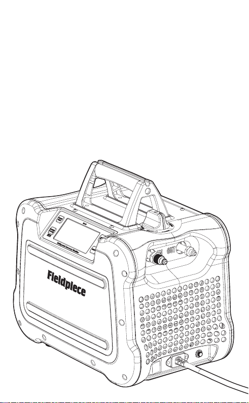
Fieldpiece MR45UK 110VAC User manual

Fieldpiece®
Refrigerant
Recovery Machine
OPERATOR'S MANUAL
Model MR45UK 110VAC

32
Contents
Safety Information. . . . . . 4
Warnings . . . . . . . . . 5
What’s Included. . . . . . . 7
Description . . . . . . . . 8
Features
Certications . . . . . . . 9
Specications . . . . . . . 10
Performance Data
Tech Tips . . . . . . . . .12
General
Setup
Operational
Controls . . . . . . . . . 14
Display and Buttons
Status Icons and Messages
Port Routing Control
MR45UK Refrigerant Flow
Dynamic Pressure Measurement
Functions . . . . . . . . . 22
Self Test
Self Purge
Purging a Recovery Cylinder
80% Overll Sensor Cable Port
Direct Liquid/Vapor Recovery
Push/Pull Recovery
Troubleshooting . . . . . . 28
Status Messages
Other Symptoms
Maintenance. . . . . . . . 30
General
Mesh Screen Filter
Limited Warranty . . . . . . 32
Obtaining Service

54
Safety Information
Read, understand, and follow this entire
manual, with special attention given to Warning
and Caution statements before operating this
machine.
For use only by qualified and certified
technicians in the safe use, handling, and
transporting of refrigerants. This machine is
designed to recover most CFC, HFC, HCFC,
and some HFO refrigerants that have an A1 or
A2L flammability rating only. Please refer to
flammable refrigerant safety guides, regional
codes and legislation for more information.
!
WARNING
FAILURE TO HEED THESE HAZARDS AND ACTIONS CAN RESULT IN
SERIOUS INJURY OR DEATH:
• Machine is only rated for use on 110VAC mains power
• Always use a grounded outlet
• Always wear Proper Protective Equipment (PPE), which includes gloves
and safety glasses and earplugs
• Know proper safety and handling requirements of the refrigerant in the
Safety Data Sheet (SDS)
• Avoid breathing refrigerant and oil vapors
• Handle hoses and equipment carefully as refrigerant is under high
pressure and can cause frost bite
• Do not operate in or near explosive atmospheres
• Do not use with hydrocarbons (HC)
• Perform leak detection in accordance with recommended practice to
verify working environment is free from leaking refrigerant as it can be
toxic and or ammable
• Only work in well-ventilated areas (minimum of 4 air exchanges per
hour)
• Ensure power and extension cords are in good working condition to
prevent shock and spark hazards
ADDITIONAL SAFETY INSTRUCTIONS FOR RECOVERING A2L
REFRIGERANTS (e.g. R-32, R-1234yf, R-1234ze):
• Adhere to local occupational safety codes and possess detailed
knowledge and skills when handling mildly ammable refrigerants
• Have emergency, evacuation, and re protection plans
• Designate and monitor aTemporary Flammable Zone with a 3-meter
perimeter
• Identify and disable all possible ignition sources within this Zone
• Monitor air with a ammable refrigerant leak detector within this Zone
• Use a ventilation fan to maintain 5 air exchanges per hour within this
Zone
• Make power connection of the recovery machine and other equipment
outside of the Temporary Hazard Zone

76
What’s Included
• MR45UK Refrigerant Recovery Machine
• 10 Extra Mesh Screens for Input Port
• 3 Extra O-ring for Input Port
• Fixed 110V Cord with Industrial Plug
• Operator’s Manual
• 2 Year Warranty
• Bond the recovery machine outlet port to the recovery tank’s unpainted
tting with a grounding strap to dissipate static electricity build up
during during recovery process
• Ensure area around machine is free of debris that could enter air vents
and fan and cause accidental sparking
• Always remain in attendance and observant when the machine is
running
• Do not mix ammable refrigerants with air
• Use an evacuated DOT recovery tank
• If system has a suspected leak, stop recovery at 0 psig/bar to prevent
air from entering the recovery tank
• After recovery, purge system with 100% nitrogen before opening
system for repair
!
CAUTION
FAILURE TO HEED THESE HAZARDS AND ACTIONS CAN CAUSE
EQUIPMENT DAMAGE:
• Ensure that recovery machine, hoses, tank and other equipment are in
good working condition
• If the power cable is damaged, it must be replaced by the
manufacturer, its service agent or similarly qualied persons in order to
avoid a hazard
• Avoid overlling recovery tanks by following refrigerant manufacturer’s
lling instructions and using a weight scale
• Avoid cross contamination by not mixing refrigerants
• Ensure mesh screen lter is installed & clean (page 30)
• Use a lter drier on the input port and change it often to protect
machine from contaminated refrigerants
• Ensure power switch is OFF before plugging into power
• Disconnect power and allow fan to stop before opening or servicing
MR45UK
• Perform self test periodically (page 22)

98
Description
The MR45UK is the first variable speed DC
motor recovery machine with a digital display.
Recover refrigerant easier and quieter than ever
before. Connect your hoses to the conveniently
placed ports without navigating around dark
tight spaces or picking the machine off the
ground. View status messages and pressures
directly on the big bright display.
Carry the lightweight machine to and from the
job site easily. Turn the single rubberized control
valve to route refrigerant through MR45UK,
and use the self-purge function to recover the
last traces into the recovery cylinder instead of
being left in the machine or released into the
environment.
Features
• Lightweight (10 kg)
• Smooth and Fast Operation (746 Watt DC Motor)
• Digital Display with Status Messages
• Reliable Rubberized Construction
• Easy to Access Port Design
• Hex Nut Secures Input Port During Hose Removal
• 80% Overll Sensor Protection Port
• Power Cord Storage
• Ceramic Cylinders
• Class A2L Refrigerant Compatible
• Self Purge
• Wide Operating Voltage (95 to 130 VAC)
Certifications
WEEE
Correct disposal of this product: This marking indicates that this
product should not be disposed with other household wastes throughout
the EU. To prevent possible harm to the environment or human health
from uncontrolled waste disposal, recycle it responsibly to promote the
sustainable reuse of material resources. To return your used device, please
use the return and collection systems or contact the retailer where the
product was purchased. They can take this product for environmental
safe recycling.

1110
Specifications
Display: 2 x 10000 count LCD with status messages
Backlight: Blue color
Measurement rate: 3.3 times per second, nominal
Input Port Pressure Sensor Range:
-76 cmHg to 4100 kPa (-30”Hg to 600 psig)
Output Port Pressure Sensor Range:
-76 cmHg to 4100 kPa (-30”Hg to 600 psig)
High Pressure Cuto: 3850 kPa (558 psig), nominal
Pressure Relief Valve: 4.2 MPa (609 psig), nominal
Resolution and Units: 5 Kpa (2 cmHg), 1 psig (1”Hg),
0.05 bar (2 cmHg), 0.01 Mpa (2 cmHg)
Pressure Sensor Accuracy:
± 1.3 cmHg, ± 0.5“ Hg (Vacuum)
± (0.6% of reading +14 kPa), ± (0.6% of reading +2 psig)
Final Recovery Vacuum: 38 cmHg, 14.9”Hg
Compressor: Twin cylinder reciprocating (oil-less)
DC Motor: 746 Watt (variable smart speed)
Power Source: 95 to 130 VAC @ 50 Hz 1 phase
Nominal Current Draw: 12.0 A
Valve: Single dual-route ball valve
Input Port Filtration: 9 mm mesh screen, stainless
Noise: Sound pressure level <70 db(A)
Dimensions: 376 mm x 250 mm x 344 mm (14.8”x 9.8”x 13.5”)
Weight: 10 kg (22 lbs)
Operating Environment: 0°C to 43°C (32°F to 109°F)
Storage Environment: -20°C to 60°C (-4°F to 140°F)
Approved Refrigerants: 12, 22, 32*, 134A, 143A*, 401A, 401B, 401C,
402A, 402B, 404A, 407A, 407B, 407C, 407D, 408A, 409A, 410A,
448A, 452A, 500, 502, 507, 509, 1234YF*, 1234ZE*
* Class A2L (mildly ammable) refrigerant
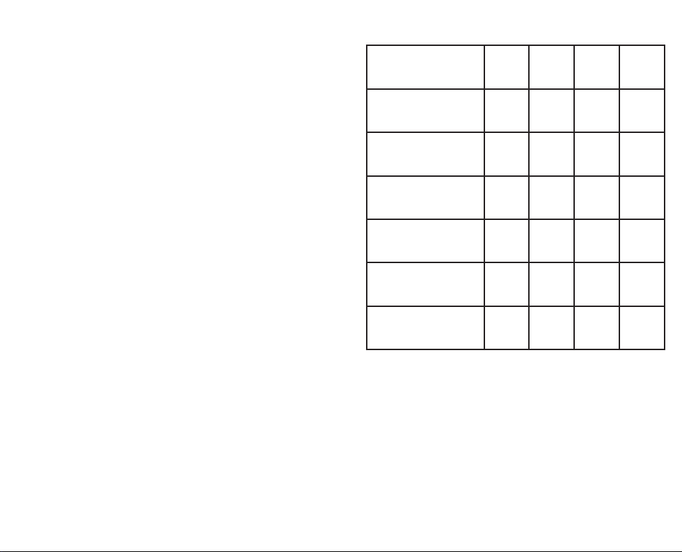
Performance Data
Refrigerant R22 R134A R407C R410A
Push/Pull Recovery
(kg/min) 4.6 5.4 5.2 7.2
Liquid Recovery
(kg/min) 4.7 2.9 5.1 5.6
Vapor Recovery
(kg/min) 0.28 0.28 0.33 0.33
Final Recovery Vacuum
(kPa) 50.8 50.8 50.8 50.8
Residual Trapped
Refrigerant (kg) 0.005 0.008 0.004 0.005
High Temp (104°F) Vapor
Recovery (kg/min) 0.40 - - -

1312
Tech Tips
General
1. Store in the self purge or recover position. Do not store in the
CLOSED position as trapped air and refrigerant can expand and
damage components.
2. For extended storage, purge with nitrogen, set to RECOVER, and
screw non-sealing caps onto the ports.
3. Recovery machines are not vacuum pumps and should not be
used for deep evacuations.
4. Do not run the machine without the mesh screen lter (page 30).
Doing so will void the warranty and damage the machine.
5. Understand the refrigerant safety data sheet (SDS).
Setup
1. Know the refrigerant of the system and make sure your recovery
cylinder matches that type.
2. Hoses:
Short as possible (3/8”hose with 1/4”tting).
Core depressors removed.
Ball valve shutos instead of low loss ttings.
Replace if worn.
3. Manifold gauges are not necessary for recovery but can make it
more convenient and increase speed by having 2 system hook
ups.
4. Use a Schrader valve core removal tool to temporarily remove
valve cores from service ports.
5. Use the push-pull method if recovering over 14 kg (30 lbs).
6. Evacuate your empty recovery cylinders to 75 cmHg (29.6”Hg)
before use for fastest recovery.
7. Know how much refrigerant you expect to recover before
starting.
8. Ensure there’s enough room in the recovery cylinder to not
exceed 80% lled during the job, or monitor and have a second
cylinder ready.
9. Always purge hoses before recovery. If cylinder is too hot, use an
ice bath to reduce the temperature and pressure of the cylinder.
10. If cylinder pressure is higher than expected, you can purge non-
condensables into another cylinder (page 23).
Operational
1. Recover as much liquid as possible before recovering vapor.
2. Recovery is faster when the recovery cylinder is cooler.
3. Recover from both suction and liquid lines at the same time for
faster vapor recovery.

Port Routing Control Knob
Input Port
Mesh Screen Filter
Backlit Digital Dual
Display and Buttons
Output Port
80% Overll
Sensor Port
(Cable Not
Included)
Power Switch (Shown ON)
Power Cord Storage
Fixed Power Cord
Port and Plug
1514
Controls

1716
Display and Buttons
Input Pressure Output Pressure
Status Icons and Messages
START/STOP
Start or Stop the motor.
ZERO (press 3 seconds)
Zero pressure sensors. Set knob to RECOVER and uncap ports.
CANCEL ALARM
Cancel alarm currently sounding (temporarily mute).
MUTE (press 3 seconds)
Toggle mute for all sounds (setting is saved).
UNITS
Select pressure/vacuum units (setting is saved).
Status Icons and Messages
The icon rotates when the motor is running.
The icon is shown when MR45UK is set to MUTE.
OK TO START
Motor stopped. Temperatures, voltages, and pressures are currently
safe to start the motor again.
COMPLETE
Motor stopped. Purge or recovery has reached 25 cmHg or 50 cmHg
(10”Hg or 20”Hg) vacuum for 10 sec.
Tank 80% Full
Motor stopped. Overll sensor triggered by liquid level of
refrigerant in the recovery cylinder.
Input Closed
Cannot zero pressures. Open input port.
Output Closed
Cannot zero pressures. Open output port.
High Voltage Warning
Motor stopped. Voltage was above 130 VAC.
Low Voltage Warning
Motor stopped. Voltage was below 95VAC.
High Pressure Cuto
Motor stopped. Output (cylinder) approached dangerous pressure.
Low Pressure Cuto
Motor stopped. Input reached 25 cmHg or 50 cmHg (10”Hg or
20”Hg) vacuum for 10 sec.
Motor Fault 1
Motor stopped. Motor temp. measured above operating range.
Motor Fault 2 (“throttle” shows on display)
Motor stopped. Motor current (amps) rose above operating range.
Throttle RECOVERY to reduce cylinder pressure (page 29).
Motor Fault 3
Motor stopped for unknown reason.
Fault 3 (“PLug O.F.S” shows on display)
80% overll Sensor not detected. Plug sensor cable into cylinder.

1918
Port Routing Control
OR
OR
CLOSED
• Input and Output closed.
• Set to either closed position to close
o both ports during setup.
OR
OR
SELF PURGE
• Input closed, Output open.
• After recovery is complete, set
to this position to close the IN port
before you START the purge.
OR
OR
RECOVER
• Input and Output fully open.
• Set to this fully open position for
most of the recovery process.
OR
OR
RECOVER (throttled)
• Input and Output partially open.
• Rotate away from RECOVER in
either direction to reduce liquid
slugging if knocking occurs.This slows
the ow of refrigerant so the machine
operates more smoothly.
• Only throttle as much as needed for
smooth operation.

2120
MR45UK Refrigerant Flow
Refrigerant liquid and vapor are pulled through
the machine by the pressure dierence created
by the compressor. For maximum performance,
increase the IN pressure and reduce the OUT
pressure. See Tech Tips (page 12).
Compressor
Input
Pressure
Sensor
Output
Pressure
Sensor
OUT
Port
IN
Port
Recovery
Cylinder
(typically)
System
(typically)
Manifold
(knob control)
Condenser
(microchannel)
Dynamic Pressure Measurement
MR45UK pressure readings are designed only
for monitoring pressures. Do not use MR45UK for
diagnostic pressure measurements.
If a system’s pressure is stable, MR45UK
pressure readings will be close to your other
pressure gauges.
If a system’s pressure is changing, pressure
measurements at dierent locations within that
system will be dierent. For every meter of 1/4”
hose, the pressure may have a difference of
approximately ± 150 kPa.

2322
Functions
Self Test
Perform this test to ensure the high pressure
cuto and pump are operational.
1. Set knob to RECOVERY.
2. Open IN port to air.
3. Connect a ball valve to OUT port. (Included caps are not sealed.)
4. Close the ball valve.
5. Press START to create a pressure at the OUT port.
6. MR45UK is working well if High Pressure Cuto occurs around 3800
kPa (550 psig) within 45 seconds. Cuto time can increase if a hose
is placed in front of your ball valve.
Self Purge
Use the SELF PURGE feature at the end of every
recovery to pump the last bit of refrigerant out
of MR45UK. Benets include increased machine
life, reduced environmental impact, and most
importantly to prevent refrigerant mixing.
1. After recovery is complete, set knob to SELF PURGE. This closes
the IN port and routes the MR45UK condenser to the intake of the
MR45UK compressor.
2. Press START to empty MR45UK into the recovery cylinder.
3. Once 25 cmHg (10”Hg) is reached for 10 seconds, the motor stops
automatically.
Purging a Recovery Cylinder
When the cylinder pressure is higher than
expected you may have non-condensables at the
top of the cylinder. Use a second deeply evacuated
cylinder to pull out the non-condensables.
1. Leave pressurized cylinder undisturbed overnight.
2. Use a vacuum pump to evacuate another cylinder.
3. Use your manifold gauges to connect the closed vapor ports of the
two cylinders.
4. Measure the vapor temperature of the pressurized refrigerant
cylinder.
5. Use a P/T chart or digital manifold to nd specied pressure.
6. Open the evacuated vapor port.
7. Open (purge) the pressurized vapor port until pressure is reduced to
35 kPa (5 psi) above specied pressure.
8. Close valves.
9. If desired, repeat in 15 minutes to allow the tank to settle again.
80% Overll Sensor Cable Port
MR45UK models have a 6.35mm (1/4”) input
for an 80% overll sensor cable (sold separately).
Always use a scale to determine how full a
refrigerant cylinder is. The overll sensor should
only be used as a secondary indicator.
1. Connect the overll sensor cable to MR45UK.
2. Connect the overll sensor cable to an equipped recovery cylinder.
3. See pages 24-27 for recovery setup and operation.
4. MR45UK automatically stops when triggered by the overll sensor.

LV
Vapor
Schrader Valve Core
Removal Tools (optional)
Filter Drier
Manifold
Cylinder
Overll Sensor
(optional)
Liquid
2524
5. Direct Liquid/Vapor Recovery
This is the typical recovery method. Vapor and
liquid lines are routed through your manifold,
into MR45UK, and out to the recovery cylinder.
CAUTION: Understand all class A2L refrigerant warnings and notices if
applicable (pages 4-6).
1. Before connecting, switch to OFF (O), then plug into power.
2. Switch to ON (I).
3. Close valves of recovery cylinder, MR45UK, and manifold.
4. Set up as shown in the diagram.
5. Open valves of hoses and removal tools.
6. Set MR45UK to RECOVER.
7. Open high side of manifold for liquid recovery.
8. To purge air from hoses, briey unseat hose tting at cylinder until
vapor is seen. Unseat hose tting at low side of manifold to purge
low side hose.
9. Fully open vapor valve of recovery cylinder.
10. Press START to begin recovery.
11. Adjust the knob as needed to throttle refrigerant ow if liquid
slugging (knocking) occurs.
12. When liquid recovery is complete, open low side of manifold for
vapor recovery.
13. MR45UK stops automatically after vacuum reaches 25 cmHg for 10
seconds. For a deeper vacuum, press START to continue recovery.
MR45UK stops again after vacuum reaches 50 cmHg for 10 seconds.
Press STOP to manually halt recovery at any time.
14. Set knob to SELF PURGE and press START to empty MR45UK.
MR45UK stops automatically after vacuum reaches 25 cmHg for 10
seconds.
15. Close manifold and cylinder valves after self purge is complete.
16. Remove hoses from MR45UK, set knob to RECOVER, and cap ports.
17. Switch to OFF (O), then unplug from power.

LV
Vapor
Liquid
Filter Drier
Cylinder
Schrader Valve Core
Removal Tools (optional)
Sight Glass (optional)
Overll Sensor
(optional)
2726
Push/Pull Recovery
This method is only for larger systems with at
least 14 kg of liquid refrigerant. It’s used to recover
liquid before recovering vapor.
CAUTION: Understand all class A2L refrigerant warnings and notices if
applicable (pages 4-6).
1. Before connecting, switch to OFF (O), then plug into power.
2. Switch to ON (I).
3. Close valves of recovery cylinder and MR45UK.
4. Set up as shown in the diagram.
5. Open valves of liquid hose and removal tool at liquid system port.
6. To purge air from system liquid hose, briey unseat hose tting at
cylinder’s liquid port until vapor is seen.
7. Fully open liquid valve of recovery cylinder and allow to pressurize.
8. Set MR45UK to RECOVER.
9. Press START to begin recovery.
10. Fully open vapor valve of recovery cylinder.
11. To purge air from hoses briey unseat hose tting at vapor system
port until vapor is seen.
12. Open valves of vapor hose and removal tool at vapor system port.
13. When liquid recovery is complete, press STOP to stop motor.
14. Close all valves and proceed to Direct Vapor Recovery (page 25).
15. Switch to OFF (O), then unplug from power.

2928
Troubleshooting
Status Messages
Tank 80% Full
Overll sensor indicated the recovery cylinder is full. Replace
recovery cylinder.
Input Closed
Cannot zero the displayed pressure because pressure sensor not
open to atmosphere. Open input port.
Output Closed
Cannot zero the displayed pressure because pressure sensor not
open to atmosphere. Open output port.
High Voltage Warning
Voltage was above 130VAC. Motor stopped. Ensure power network
voltage is between 95-130VAC @ 50 Hz.
Low Voltage Warning
Voltage was below 95 VAC. Motor stopped. Check power network to
ensure voltage is between 95-130 VAC @ 50 Hz.
High Pressure Cuto
Output (cylinder) reached dangerous pressure. Motor stopped.
Ensure all valves after the output port are open.The cylinder may need
to be cooled or replaced to reduce pressure.
Low Pressure Cuto
Input reached nal recovery vacuum. Motor stopped. It’s normal
to see this after RECOVERY or SELF PURGE is complete. Ensure valves
before the input port are open and the knob is not set to CLOSED.
Motor Fault 1
Motor temperature above operating range. Motor stopped.
Extremely high ambient temperature, extended liquid recovery time,
or high cylinder pressure can be the cause. Allow time for the motor to
cool down before resuming, and throttle the RECOVERY (page 19).
Motor Fault 2 (“throttle” shows on display)
Motor current (amps) rose above operating range. Motor stopped.
Extremely high ambient temperature, harsh liquid slugging, extended
recovery time, or high cylinder pressure can be the cause.Throttle
RECOVERY and start the motor. If fault occurs again, throttle even more
and start the motor (page 19).
Motor Fault 3
Motor stopped for unknown reason. If this occurs repeatedly, there
may be something wrong with MR45UK.
Fault 3 (“PLug O.F.S” shows on display)
80% overll Sensor not detected. Plug sensor cable into cylinder.
Other Symptoms
MR45UK never reaches 25 cmHg or 50 cmHg.
Check for a leakage before the input port.
Recovery cylinder should be below 3200 kPa for 25 cmHg vacuum.
Recovery cylinder should be below 1600 kPa for 50 cmHg vacuum.
Input port shows frost or signs of leakage.
Ensure the grooved input tting is hand tight before tightening the
hex nut (page 34).
Recovery is slower than normal.
There could be an input blockage. Check mesh screen lter for
blockage. Ensure knob is set to RECOVER.
Display does not turn on when plugged in.
Ensure power cord and outlet are okay.
Ensure power switch is ipped ON after plugging into power.
Excessive noise during liquid recovery.
MR45UK is experiencing a high load. Rotate the knob of MR45UK to
throttle the refrigerant ow.
Overll sensor not working correctly.
Check for loose connection. Overll sensor may be broken.Verify
overll with scale. If overll sensor is bad, mark tank for disposal.

1.
2.
3.
4.
5.
Done
O-ring
Screen
Securing Hex Nut
Grooved Input Fitting
3130
Maintenance
General
Wipe with damp cloth to clean the exterior.
Do not use solvents.
To extend the life of internal seals, occasionally
pump a teaspoon of mineral oil through MR45UK.
Mesh Screen Filter
When the mesh screen lter becomes dirty
and clogged, it means it’s working to keep your
MR45UK working well for a long time. You need
to clean or replace this screen often. Visit our
website for information on obtaining extra mesh
screens.
1. Loosen (counter clockwise) the securing hex nut on the IN port.
2. Unscrew (counter clockwise) the grooved input tting.
3. Clean or replace the mesh screen.
4. Hand tighten (clockwise) the grooved input tting.
5. Tighten (clockwise) the securing hex nut with 1/8 turn with a
wrench.

3332
Limited Warranty
This machine is warranted against defects in
material or workmanship for two years from date
of purchase from an authorized Fieldpiece dealer.
Fieldpiece will replace or repair the defective unit,
at its option, subject to verication of the defect.
This warranty does not apply to defects
resulting from abuse, neglect, accident,
unauthorized repair, alteration, or unreasonable
use of the machine.
Any implied warranties arising from the sale of
a Fieldpiece product, including but not limited to
implied warranties of merchantability and tness
for a particular purpose, are limited to the above.
Fieldpiece shall not be liable for loss of use of the
machine or other incidental or consequential
damages, expenses, or economic loss, or for any
claim of such damage, expenses, or economic
loss.
Local laws vary. The above limitations or
exclusions may not apply to you.
Obtaining Service
Warranty for products purchased outside of the
U.S. should be handled through local distributors.
Visit our website to nd your local distributor.

MR45UK
© Fieldpiece Instruments, Inc 2022; v01
Table of contents
Other Fieldpiece Test Equipment manuals