ELABO 90-4F User manual

Operating manual
PE conductor tester
90-4F
DIN EN ISO 9001
certified
Calibration at ELABO factory
Calibration at customer premises
Test units on loan
Hotline ++49 7951/307-0
ELABO GmbH
D-74564 Crailsheim
LGA
ELABO after sale service:

2
PE-Conductor Tester 90-4F
Description
&RQWHQWV
A DESCRIPTION OF FRONT PANEL CONTROLS ...................................3
1. INTRODUCTION......................................................................................5
1.1 GENERAL INFORMATION .....................................................................5
1.2 ABBREVIATIONS AND SYMBOLS ........................................................6
1.3 SHORT DESCRIPTION OF THE PE CONDUCTOR TESTER ................ 6
1.4 GENERAL DATA..................................................................................... 7
1.5 NAME PLATES .......................................................................................7
2. SAFETY REGULATIONS ........................................................................8
2.1 SIGNS OF SAFETY AND WARNING REGULATIONS ...........................8
2.2 WARRANTY ............................................................................................ 8
2.3 USE AS PER SPECIFICATIONS AND EXCLUSION OF LIABILITY ...... 8
2.4 GENERAL RULES OF CONDUCT AND SAFETY REGULATIONS ....... 9
2.5 PARTICULAR REFERENCES TO THE PE CONDUCTOR.......................
TESTER....................................................................................... 10
3. PUTTING INTO OPERATION................................................................ 11
3.1 TRANSPORT AND INSTALLATION ..................................................... 11
3.2 CONNECTION ....................................................................................... 11
3.3 SETTING THE TEST UNIT PARAMETERS .......................................... 12
4. OPERATING MODES............................................................................ 14
4.1 MEASURING PRINCIPLE ..................................................................... 14
4.2 PROTECTIVE CONDUCTOR TEST WITHOUT SAFETY PLUG........... 15
4.3 TEST with SAFETY PLUG.................................................................... 16
4.4 TEST WITH TEST PROBE .................................................................... 17
4.5 OPERATION IN COMBINATION WITH AN INSULATION
TESTER....................................................................................... 18
5. OPERATION VIA INTERFACE.............................................................. 19
5.1 PIN ASSIGNMENT OF INTERFACE TERMINAL STRIP (X7)............... 19
5.2 TERMINAL ASSIGNMENT OF THE 11-PIN VG CONNECTOR (X1) .... 20
5.3 TERMINAL ASSIGNMENT OF THE TERMINAL BLOCK (X6) ............. 21
6. FAULT INDICATIONS ........................................................................... 22
7. MAINTENANCE AND ATTENDANCE .................................................. 23
7.1 EXCHANGE OF FUSES ........................................................................ 23
7.2 SERVICE OF THE HOUSING................................................................ 24
8. TECHNICAL DATA ............................................................................... 25
9. APPENDIX............................................................................................. 26
9.1 COMPONENT LOCATION ILLUSTRATION OF SUBASSEMBLY
PE200 / PE300............................................................................. 27
9.2 COMPONENT LOCATION ILLUSTRATION OF SUBASSEMBLY
PEIS200 ....................................................................................... 28
9.3 WIRING DIAGRAM................................................................................ 30

3
PE-Conductor Tester 90-4F
Description
X2 X3.2 X4.2 X4.1 X3.1 S1/H1
A3 S2 S4 R2 S3 R1
V3
V4
V5
V2
V1
X5
X1 X6-3 X6-1 X7
A DESCRIPTON OF FRONT PANEL CONTROLS
Front panel
Rear side
contact 1 / 3
4
PE-Conductor Tester 90-4F
Description
A DESCRIPTON OF FRONT PANEL CONTROLS
.oN.oN .oN .oN.oNtnempiqEtnempiqE tnempiqE tnempiqEtnempiqEnoitarepOnoitarepO noitarepO noitarepOnoitarepO
3AtnerrucdnaecnatsiseR
tnemurtsnignirusaem
tigid2/13
egnaryalpsiD
mhOm053...0ecnatsiser
A52...0tnerruc
1RretemoitnetoPRfognitsujdA
xam
)desserpsi3Snottub-hsupgnidivorp(
2RretemoitnetoPIfognitsujdA
mon
tnemerusamgnidivorp(A52....0morf
)desserpsi4Snottub-hsupehtdnavitcasinoitarepo
1H/1ShctiwsrekcordetanimullI yalpsidedomgnihctiwshtiwgnihctiwsFFO/NO
2SnottubhsuP.tnemerusaemfotrats-TRATS
yalpsideht4S/2Snottub-hsupfognisserpylsuoenatlumistA
.3Anodeveihcasitnerructsetehtfo
3SnottubhsuP dna1RtadetsujdaebnacxamR-detareposi3SfI
3Anodeyalpsid
4SnottubhsuP 3Anodeyalpsidsitnerruclanimoneht-detareposi4SfI
1VwolleyDELnoitareponisitset-EPeht-NUR
2VneergDEL I>IdnaxamR<eulavgnirusaem-TPECCA
nim
"dessaP"
3VderDELR>R
xam
xamRehtnahtrehgihecnatsiserretcudnocEP-
"tluaF"
4VderDELI<I
nim
Inahtrewoltnerructset-
nim
)%01-I(
5VderDEL tontratstseT.erutarepmetrevoretsoob-DAOLREVO
.elbissop
2XteltuodnuorG
)okuhcS(dradnatsnamreG
tcejbotsetehtfonoitcennoC
1.3XskcaJ S4-49eborptsetEPehtforotcejbotsetehtfonoitcennoC
2.3XskcaJtcejbotsetehtfonoitcennoC
1.4XlanimretbalytefaS )1.3Xgnidrager(sdaelrosnesehtfonoitcennoC
2.4XlanimretbalytefaS )2.3Xgnidrager(sdaelrosnesehtfonoitcennoC
5X.lop-5tekcosedoiD tnerructset(S4-49eborptsetEPehtfonoitcennoC
)1.3Xgnidrager
1X
)edisraer(
rotcennocGVnip-11ylppussniaM
1-6X
)edisraer(
lanimretbalytefaS =1-6X.retsetehtfoedisraernotcejbotsetfonoitcennoC
.tnorfno1.3X
3-6X
)edisraer(
lanimretbalytefaS =3-6X.retsetehtfoedisraernotcejbotsetfonoitcennoC
tnorfno2.3X
7X
)edisraer(
rotcennocGVnip-46
)ecafretni-AD(
dnatupnisuoiravfolortnoclanretxerofrotcennocecafretnI
slangistuptuo
5
PE-Conductor Tester 90-4F
1. Indroduction
1. INTRODUCTION
The security of all persons coming into contact with the test unit is decisively
dependent upon the mastery of the unit. Therefore:
Read the operating instructions before
the first putting into operation!
1.1 GENERAL INFORMATION
The operating instructions enable the user to become familiar with the
tester and its application possibilities and to use it as per the specifications
before the first operation. They contain important information which
guarantee a functional, economic and safe operation and have to be
available always at the operational place of the tester.
The operating instructions are not only an indispensable lead-in for
operators who have to be instructed from the very beginning but they also
contain useful tips, information and suggestions for the skilled operator.
They are a necessary reference book for all operators. By reading the
operating instructions
•dangers are avoided
•sequences of operations are optimized and accelerated
•cost of repair and times of standstill are minimized
•reliability and service life are increased
The operating instructions should also be attentively read by the unit owner
and the person responsible for the operation. Particularly with regard to
transport and installation as well as warranty questions.
In chapter 2 important information regarding security and risks are given
which prepare you for danger situations that may arise. During operation
it is unfortunately too late to read again. In addition to this please, note the
following rule:
Cautious and careful working is the
best protection from accidents!
The testing quality of the unit is decisively dependent on maintenance
and attendance. Regular activities concerning maintenance and
attendance are described in these operating instructions. We have pleasure
in supporting you in case of necessary repairs and supply you with the
original spare parts.
If you have any questions after reading the operating instructions the
ELABO Hot -line (Telephone 07951/307-0) is at your disposal for further
details.
For better use of the operating instructions the cover page can be opened
out. Through this the illustration of the front or rear panel of the unit is
always visible for the user while reading the operating instructions.
6
PE-Conductor Tester 90-4F
1. Indroduction
•1
•
SO
ä
1.2 ABBREVIATIONS AND SYMBOLS
Special option, does not belong to the standard delivery extent
Enumeration, the recommended sequence is to be observed herewith
Enumeration
ATTENTION ELECTRIC VOLTAGE !
Danger spot to users and third persons! - Chap. 2.1
Danger to the instrument ! - Chap.2.1
Reference for the effective and economic mode of operation - Chap. 2.1
1.3 SHORT DESCRIPTION OF THE PE CONDUCTOR TESTER
The measuring instrument 2GA27 90-4F serves for the testing of the
efficacy of the PE conductor connection, for
electrical devices for measurement, controlling and laboratory
according EN61010 (DIN VDE 0411),
electrical devices of the household, according EN60335 (DIN VDE
0700),
equipment of information technology and office machines,
according EN60954 (DIN VDE 0805).
The test current is stepless adjustable between 10 to 25 A. Through the
employed test method the resistance value will be calculated from current
and voltage with high precision.
The resistance is displayed during the entire testing time by means of an
3 1/2 digit digital display.
The test object can be connected alternatively to a socket outlet or via
two terminals.
At the test device a maximum permissible resistance can be adjusted
individually. If the preset resistance R max is exceeded during a
measurement, a visual error is displayed (LED R > Rmax).
The device includes a watch-dog function for monitoring the test current.
If the test current underruns the adjusted test current at 10 %, a visual
error is displayed (LED I > Imin).
In order to achieve a non-destructive test the test current is switched on
only after operating the push-button START resp. after pressing the tip of
the test probe in.
The test device is set up as subdrawer with 36 pitches and conceives
already in the standard design for program-controlled application. The
connection is conducted via a multiple connector according to DIN 41612.

7
PE-Conductor Tester 90-4F
1. Indroduction
1.4 GENERALDATA
Type of test: reference EN 61010 (VDE0411),
EN60335 (VDE0700),
EN60950 (VDE 0805)
Duty cycle: 10 %, max. operating time 1.5 min.
Output voltage: max. 10 V AC
Test current : 10 to 25 A
Measuring range: 0 to 350 mOhm
Working temperature: 10oC to 50oC
Atmospheric humidity: 25 - 75% rel. air humidity
Power supply: 230 V +10% -5%/ 49 to 61 Hz
Dimensions: Euro-Subdrawer 3 HU/36 pitches. Depth 196 mm
Weight: 6 kg
1.5NAMEPLATES
ELABO PE-Conductor Tester 90-4F.
Fig. 1.1: ELABO name plate
SN. 0000042483
ELABO GmbH
Rossfelder Str. 56
D-74564 Crailsheim
Telefon: +49 7951 307-0
Telefax: +49 7951 307-65
Nennspg. V
~
Nennstrom A
Typ
Baujahr
230 V ; 49 - 61 Hz
1.2 A
90-4F
2004
8
PE-Conductor Tester 90-4F
2. Safety regulations
2. SAFETY REGULATIONS
Before working with the device the operating instructions and all enclosures
must have been attentively read and understood by all persons operating
the tester. The tester may be operated by trained and skilled staff only.
ELABO has equipped the unit with all necessary safety devices when
using them as per the specifications in order to protect the operator from
appearing risks. Pay attention:
CAUTIOUS AND CAREFUL WORKING IS THE
BEST PROTECTION FROM ACCIDENTS !
2.1 SIGNS OF SAFETY AND WARNING REGULATIONS
Danger Area! Electric Voltage - Danger to life !
IN DEALING WITH ELECTRIC VOLTAGE THERE IS DANGER TO LIFE!
This sign warns of a danger area through electric voltage. It is situated at
all working cycles where life of the operator and other persons is
endangered. It is situated at working and operating procedures which
have to be observed accurately in order to prevent endangering of persons
or the tester by electric voltage.
Caution !
This sign signifies danger to the tester in case of non-observance of in-
struction.
Information !
This sign signifies that a more effective and more economic use of the
tester is possible.
2.2 WARRANTY
Claims for warranty can only be asserted when the terms of warranty
included in the general terms of sale and delivery are observed.
Furthermore, the terms of the operating instructions have to be observed.
2.3 USE AS PER SPECIFICATIONS AND EXCLUSION OF
LIABILITY
The device has to be used as per the specifications only for the intended
tests. Every use beyond is considered as not according to the
specifications. ELABO does not accept any liability for damages resulting
from this, the operator exclusively carries the risk. It is also necessary for
the use as per the specifications that the information given in these
operating instructions is observed.
The device and its components have been developed and constructed
9
PE-Conductor Tester 90-4F
2. Safety regulations
for the application in the industrial field. According to DIN EN 55022 ITE
this unit represents a system of class A. Neither the device as a whole or
the single components of it may be employed in another environment. In
case of non-observance of this information ELABO does not accept any
liability for appearing malfunctions and damages resulting from this.
These operating instructions and all enclosures must have been attentively
read and understood by all operators before working with the device. The
device has to be operated by trained and skilled staff only.
The unit may not be changed regarding construction and safety technology.
Every alteration needs the particular approval of ELABO.
Unauthorized modifications at the device as well as the use of spare parts,
accessories and extra equipments which have not been controlled and
released by ELABO can have a negative influence on the function and
features of the device. ELABO does not accept any liability for damages
resulting from this.
ELABO does not accept any liability for damages arising by non-
observance of the operating instructions or by negligence of duty of care
during the transport, installation, handling, operation, attendance and
maintenance or during repair of the unit even if these duties of care are
not particularly pointed to in the operating instructions.
2.4 GENERAL RULES OF CONDUCT AND SAFETY
REGULATIONS
The device was built according to the state of art and approved safety
regulations. Nevertheless, there might arise danger to life of the operator
or third persons respectively damages at the tester or other material goods.
The device has to be operated in workmanlike condition only and according
to the specifications under observance of the operating instructions. Faults
impairing the safety have to be cleared immediately.
The person responsible for the operation has to attend to that the staff
charged with work at the device must have read and understood the
operating instructions before commencement of work. The person
responsible for the device operation is obliged to always operate the device
in perfect condition only and to instruct the service staff to use the unit as
per the specifications.
The operating instructions have to be always available at the operational
place of the device. Incomplete or illegible operating instructions have to
be replaced immediately. Of course, we are pleased to be of help to you
in this respect.
In addition to the operating instructions legal, generally valid and other
obligatory regulations for accident prevention and environmental protection
have to be observed.

10
PE-Conductor Tester 90-4F
2. Safety regulations
2.5 PARTICULAR REFERENCES TO THE PE CONDUCTOR
TESTER
Before opening the unit pull out power supply plug!
Switching off by means of rocker switch (S1/H1) is insufficient!
The PE contact of the safety socket outlet is not connected to PE
conductor potential!
The safety socket outlet at the front panel of the test unit is not a power
supply socket outlet for consumer articles but exclusively a measuring
socket outlet for the connecting of item on tests with earth safety plugs.
The PE conductor tester is for short-term measurements only, as usual
for PE conductor measurements. Continuous operation of the instrument
can lead to damages.
11
PE-Conductor Tester 90-4F
3. Putting into operation
3. PUTTING INTO OPERATION
3.1 TRANSPORT AND INSTALLATION
The PE conductor tester is delivered completely packed and may only be
taken out of package directly at the operational place.
The unit is designed to be operated in a suitable rack. As an option is a
housing available for application as stand-alone-unit (ELABO-accessory:
Catalogue-No. 2GA27 30-6M). The unit must not be operated outside a
rack or housing.
The operational surface has to suit the weight of the tester (6 kg!) and
provide a safe support for the unit at any time.
The environment of the testing unit must be clean, dry and dust-free.
When installing the tester pay attention that the information and safety
signs at the unit are not covered.
3.2 CONNECTION
The tester can be connected to the mains supply via a 11 pole multiple
connector (X1) located on the rear of the unit.
When inserting into the rack, the mains supply connector at the rear side
of the unit will be connected to the mains supply connector installed in the
rack. Thus, the unit is automatically connected to the power supply.
After inserting the unit into the rack it must be tightly fitted by means of the
two screws located on the front panel.
The operation with a loosely inserted
test unit is not permissible!
12
PE-Conductor Tester 90-4F
3. Putting into operation
3.3 SETTING THE TEST UNIT PARAMETERS
Before the unit is put into operation some parameters must be adjusted.
Switch on unit with illuminated rocker switch (S1/H1). The pilot lamp (S1/
H1) lights up.
Setting of Rmax
Press push-button S3 and set the trimming potentiometer R1 to the maxi-
mal permissible resistance value in the range from 0 to 350 mOhm. The
set value is displayed at the display A3.
Setting of the test current
The test current is adjustable between 10 to 25 A.
In order to adjust the test current, the measuring circuit must be closed by
making a short circuit of the measuring leads.
When using a test probe (SO) the tip of the probe must be pressed onto
the terminal jack X3.2.
Press push button START (S2) and push button I act (S4) simultaneously
and adjust the required test current with trimming potentiometer R2 in the
range of 10 to 25 A. The test current is displayed on instrument A3.
Press push-button S3 and set the trimming potentiometer R1 to the maxi-
mal permissible resistance value in the range from 0 to 350 mOhm. The
set value is displayed at the display A3.
If the lower limit value of the test current is undershot, a red LED V4
(I < Imin) lights up. Nevertheless the test can be carried out. It should be
noted that the accuracy indicated is no longer guaranteed if the test current
falls below I - 10 %. There is no „Accept“ indication by LED V2.
Setting the alarm buzzer.
The buzzer can be set inside the test unit to different modes by setting
jumpers on the subassembly PEIS200.
Work inside the test unit are to be carried out by
an electrical specialist only!
The unit has to be disconnected from the mains if
work is to be carried out inside the unit!
The presetting at works is marked with an #.

13
PE-Conductor Tester 90-4F
3. Putting into operation
Buzzers as GO - or FAULT - signal.
B1: Jumper 1-2 > FAULT-signal
2-3 > Go-signal #
Buzzer ON or OFF.
B2: Jumper 1-2 > ON #
open > OFF
Buzzer for timer mode or Go/Fault evaluation
B5 Jumper 1-2 > Timer mode
2-3 > Fault evaluation #
The Fig. 3.1 shows the location of the jumper on the subassembly.
For more information see the component location illustration of PEIS200
(Chapt. 9.2).
subassembly PEIS 200
Fig. 3.1: Subassebly PEIS200 - buzzer setup

14
PE-Conductor Tester 90-4F
4 Operating modes
Fig. 4.1: Measurement principle of the PE conductor tester
PE-contact test point
10V
current
Sensor
Rx
4. OPERATING MODES
Before starting of the measuring operation the adjustments must be carried
out according to Chap. 3.3.
4.1 MEASURING PRINCIPLE
Illustration 4.1 shows the measuring principle of the PE conductor tester.
For the measurement a test current is taken from an AC source with a no-
load voltage of 10 V. The amount of the test current conforms with the
valid VDE-standards.
The current is applied between the PE-terminal and every touchable metal
part in turn. The resistance is then calculate from the current and the
voltage measured between the PE -terminal an the touchable metal parts.
The test current and the open circuit voltage are electronically stabilized.
Therefore it is not necessary to readjust the test current after changing
the item under test.
The instrument can be used for tests with or without safety plug socket as
well as for tests with a test probe.
Use exclusively safety checked leads for the connection of the test
object to the measuring instrument !
Use never damaged or defective leads or power supply cable for
the connection of the test object !
Check the condition of the leads before each measurement !
The result of the protective conductor test will be displayed via the LED
V2, V3 and V4. The green LED V2 signals a faultless test, while the red
LED V3 and V4 will display a fault. The buzzer supports the display
according to the setting (Chap. 3.3).
15
PE-Conductor Tester 90-4F
4 Operating modes
Rx
4.2
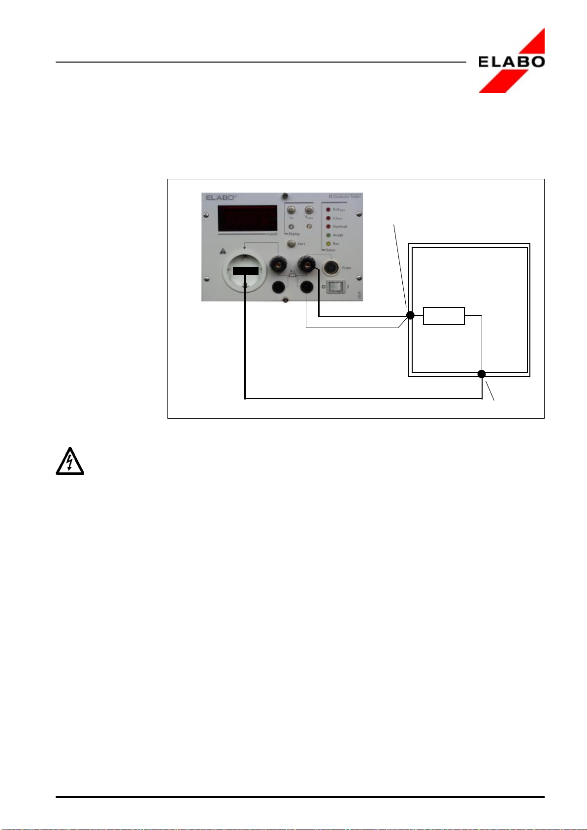
PROTECTIVECONDUCTORTESTWITHOUTSAFETYPLUG
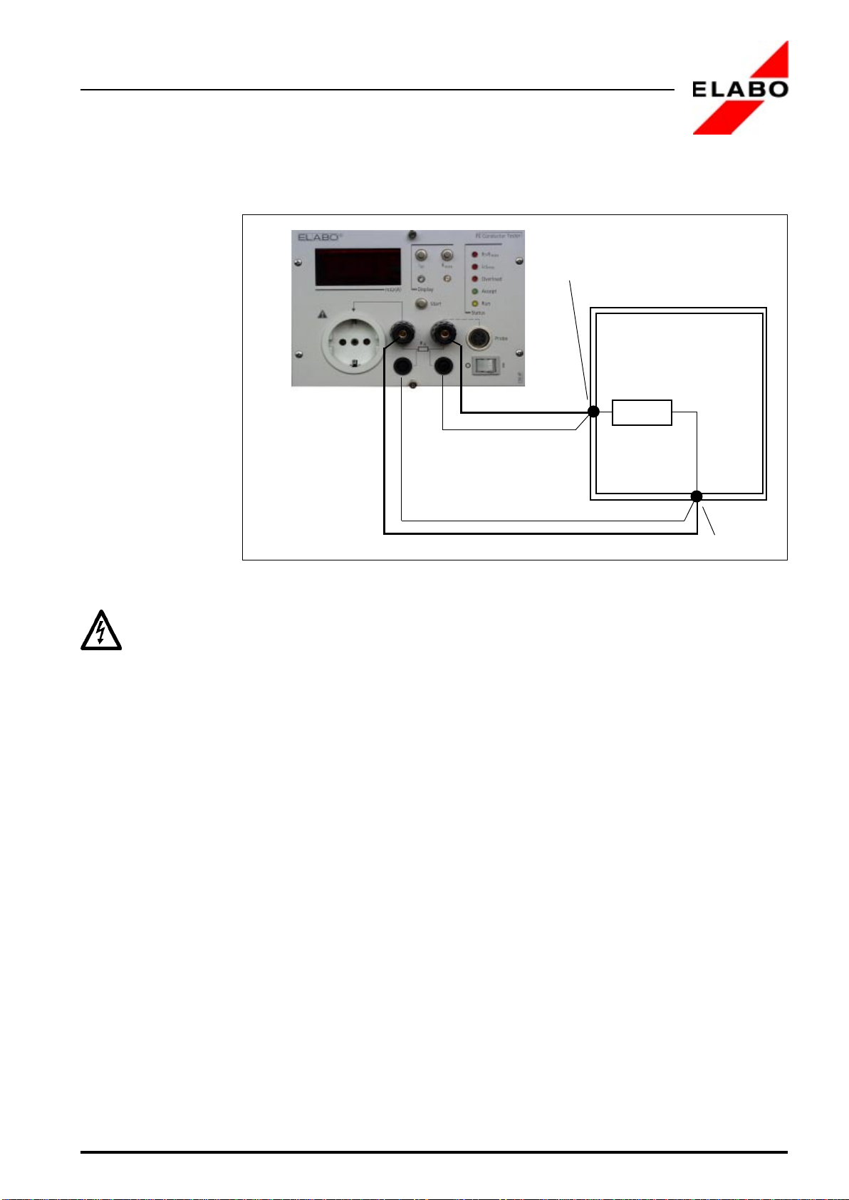
Ills. 4.2 shows the test arrangement for this operating mode.
For the connection of the item on test to the terminals of the instrument
use connecting leads with a cable cross-section of at least 2.5 mm² !
Connect the PE conductor of the test object with the connecting terminal
(X3.2) and the safety lab terminal (sensor) (X4.2). Connect the cable from
connecting terminal (X3.1) to the test point. Connect a sensor cable from
the safety lab terminal (X1.1) to the test point.
Start the measurement by means of the start push-button (S2) or via
interface start.
test object
PE-contact
test point
Fig. 4.2: Test arrangement for measurements without safety plug
16
PE-Conductor Tester 90-4F
4 Operating modes
Rx
test object
PE-contact
test point
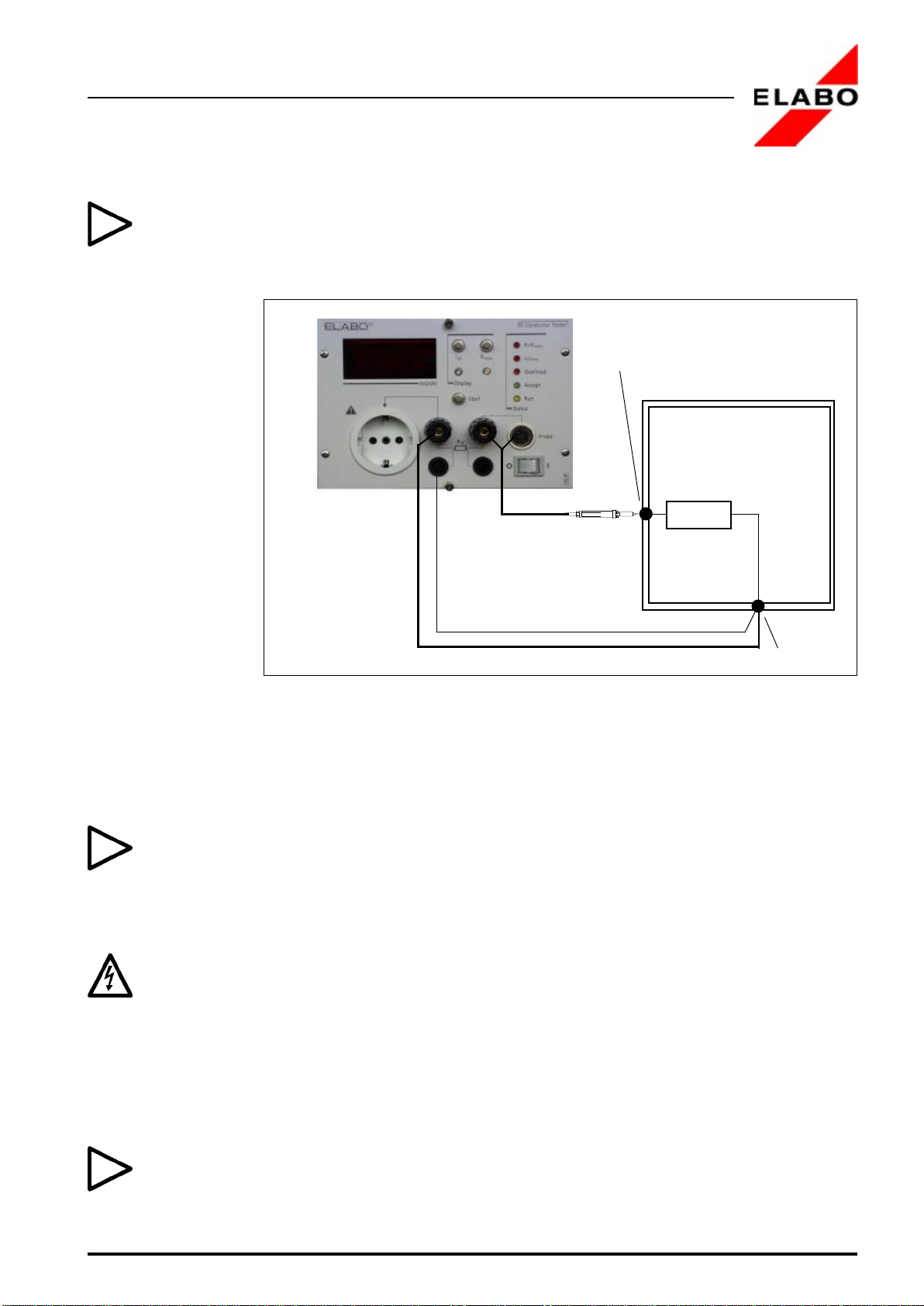
4.3 TEST WITH SAFETY PLUG
Fig. 4.3 shows the test arrangement for the measurement with a safety
plug.
Use a power supply cable with a cable cross-section of at least 1 mm² for
the connection of the item on test to the socket outlet of the instrument!
Put the power supply cable of the item on test into the socket outlet (X2).
Connect the cable from the connecting terminal (X3.1) to the test object.
Connect sensor cable from safety lab terminal (X4.1) to the test point.
Start the measurement via the start push-button (S2).
Fig. 4.3: Test arrangement for measurements with safety plug
17
PE-Conductor Tester 90-4F
4 Operating modes
Rx
test object
PE-contact
test point
4.4 TEST WITH TEST PROBE
For a simpler operation the measuring instrument can be operated with a
test probe. (ELABO - accessory: Catalogue-No. 2GA27 94-4S).
Fig. 4.4 shows the test arrangement with a test probe and without a three
wire plug.
Put the 5 pole diode plug of the test probe into the diode socket (X5) and
secure by means of screwing against unintentional loosening.
Put the 4 mm plug of the test probe into the socket X3.1.
For operation with a test probe the adjustment of the test current can be
achieved by pressing the tip of the test probe against the PE-conductor
terminal of the test socket outlet or the socket X3.2 and simultaneously
operating of the Iact -push-button (S4).
With the test probe are measurements with and without safety plugs
possible, as described under Chap. 4.2 and 4.3.
Consider, when connecting, the references mentioned in Chap. 4.2 and
4.3.
Connect the test specimen to the socket outlet (X2) or to the terminals
(X3.1) and (X3.2).
The tip of the test probe must be pushed-in completely at the test point of
the item under test.
To prevent contacts and measuring points of the specimen from charring,
the test current will not be applied before the spring-loaded tip of the test
probe is pushed-in completely.
Fig. 4.4: Test arrangement for measurements with test probe
18
PE-Conductor Tester 90-4F
4 Operating modes
4.5 OPERATION IN COMBINATION WITH AN INSULATION
TESTER
Together with the ELABO-Insulation tester (Catalog-No. 2GA27 90-2E) a
simultaneous measurement of PE conductor and insulation resistance is
possible.
Consider for the connection of the item on test absolutely
the references given in Chap. 4.1 - 4.4 !
For the combination measurement the item on test must be contacted
always at the PE conductor tester. Otherwise the insulation tester can be
damaged.
The actuation of the start push-button at the PE conductor tester
triggers the protective conductor and insulation resistance
measurement. An actuation of the start push-button at the insulation tester,
triggers the insulation test only.
If the protective conductor test proceeds faultlessly, the insulation test is
started automatically. A fault at the protective conductor test will give a
„Fault“ alarm at the PE conductor tester, the insulation test is not started.
The buzzer in the PE conductor tester must be in position „OFF“ during
the combination operation (see appendix). If possible, the interface should
be operated floating.
19
PE-Conductor Tester 90-4F
5 Interface
5. OPERATION VIA INTERFACE
The PE conductor tester disposes of an interface which enables the
external control and evaluation.
The signal level of the input should be between 5 V and 24 V. The
connections a and c of 64 pole terminal strip (X7) are linked.
The operating and display elements on the front panel have the external
control during their full function.
The connections of the test current and the sensor cable are in parallel to
the front panel terminals during operation via the external interface. It is
recommended to operate the interface control floating, since the ground
potential of the interface is not electrical isolated from the test signal.
5.1 PIN ASSIGNMENT OF INTERFACE TERMINAL STRIP (X7)
In the following, the pin assignment of the 64 pole terminal strip (X8) is
described. The terminal strip corresponds to DIN 41612, Type C).
Attention: The control Inputs/Outputs (Pin 2, 4, 6, 9, 10, 14) as well as
the analog outputs (Pin 27) at the 64-pole interface (X8) have a fixed
potential to the test current.
If for instance, the control is carried out by a grounded PLC via the before
mentioned Pins then the current source which generates the test current
is also grounded. Thus, a falsification of the test results becomes possible.
Pin 2 Good/Fault.
Open collector of transistor BD 675 for
„Good/Fault“ identification:
Transistor conductive = GOOD
Transistor blocking = FAULT
Pin 9 and 14 GND
Reference potential of all inputs and outputs.
Pin 4 GNDR
Reference potential of the floating input "Start H".
For more information see Chapt. 9.2 Appendix.
Pin 6 Start L.
Connection of Pin 6 to GND acts like operating key
„Start“ (S2).
If possible use floating contacts.

20
PE-Conductor Tester 90-4F
5 Interface
Pin 8 Measuring H.
Applying of an external DC of 5 V to 24 V, acts like
operating key „Start“ (S2).
For more information see Chapt. 9.2 Appendix.
Pin 16, 18 Fault I
Floating relay output for identifying off-limit test
currents.
No connection between pins 16 and 18 in the event of a
fault (contact open).
For more information see Chapt. 9.2 Appendix.
Pin 20, 22 Fault R
Floating relay output for identifying over-ranging
resistance values.
No connection between pins 20 and 22 in the event of a
fault (contact open).
For more information see Chapt. 9.2 Appendix.
Pin 27 Rnom (Rist)
Analog DC signal as a function of the resistance:
0. . .350 mOhm = 0 to 10 V DC, measured against
GND.
Maximum loading capacity 5 mA.
Pin 29 Sensor left.
Sensor lead, parallel to left-hand sensor jack (X4.2).
Pin 31 Sensor right.
Sensor lead, parallel to right-hand sensor jack (X4.1).
Table of contents
Other ELABO Test Equipment manuals


