Tenma 72-7985 User manual

TRADEMARKS USED IN THIS MANUAL
Tenma Test Equipment, Tenma, and (logo) are trademarks of
MCM, an InOne company.
Apple and Macintosh are registered trademarks of Apple Computer, Inc.
IBM is a registered trademark of International Business Machines
Corporation.
SGI is a registered trademark of Silicon Graphics, Inc.
Sun and Sun Microsystems are registered trademarks of Sun Microsystems,
Inc. in the United States and other countries.
Any other trademarks mentioned in this manual are acknowledged to be the
property of the trademark owners.
© Copyright 2005, Tenma Test Equipment. All rights reserved.
405 S. Pioneer Blvd. Springboro Ohio 45066
Downloaded from Arrow.com.Downloaded from Arrow.com.

FEDERAL COMMUNICATIONS COMMISSION
AND CANADIAN DEPARTMENT OF COMMUNICATIONS
RADIO FREQUENCY INTERFERENCE STATEMENTS
This equipment generates, uses, and can radiate radio frequency energy
and if not installed and used properly, that is, in strict accordance with
the manufacturer’s instructions, may cause interference to radio
communication. It has been designed to comply with the limits for a
Class A computing device in accordance with the specifications in
Subpart B of Part 15 of FCC rules, which are intended to provide
reasonable protection against such interference when the equipment is
operated in a commercial environment. Operation of this equipment in
a residential area is likely to cause interference, in which case the user,
at their own expense, will be required to take whatever measures may
be necessary to correct the interference.
Changes or modifications not expressly approved by the party
responsible for compliance could void the user’s authority to operate
the equipment.
This digital apparatus does not exceed the Class A limits for radio
noise emission from digital apparatus set out in the Radio Interference
Regulation of the Canadian Department of Communications.
EUROPEAN UNION DECLARATION OF CONFORMITY
This product has been tested and shown to comply with the
requirements of the European EMC directive 89/336/EEC
Downloaded from Arrow.com.Downloaded from Arrow.com.Downloaded from Arrow.com.

Contents
1. Introduction ..............................................................................page 4
1.1 General ................................................................................page 4
1.2 Features ...............................................................................page 4
2. Installation .................................................................................page 5
3. Operation ...................................................................................page 5
4. Troubleshooting.........................................................................page 9
5. Specifications...........................................................................page 10
© Copyright 2005, Tenma Test Equipment. All rights reserved.
405 S. Pioneer Blvd. Springboro Ohio 45066
Downloaded from Arrow.com.Downloaded from Arrow.com.Downloaded from Arrow.com.Downloaded from Arrow.com.

1. Introduction
1.1 General
Thank you for purchasing the Tenma Model 72-7985 Pattern Generator, for
high-resolution display devices.
The unit provides DVI, PC (VGA through SXGA), and HDTV Component
Video (Y,Pb,Pr) outputs. The Model 72-7985 features 28 static and dynamic
video test patterns specially designed for testing, calibrating, and
troubleshooting high end video gear and A/V installations.
In addition to all of standard PC resolutions and refresh rates (up to SXGA at
85 Hz), it is capable of providing HDTV outputs from 480p to 1080i both in
DVI digital and in YPbPr formats. The On Screen Display (OSD) indicates
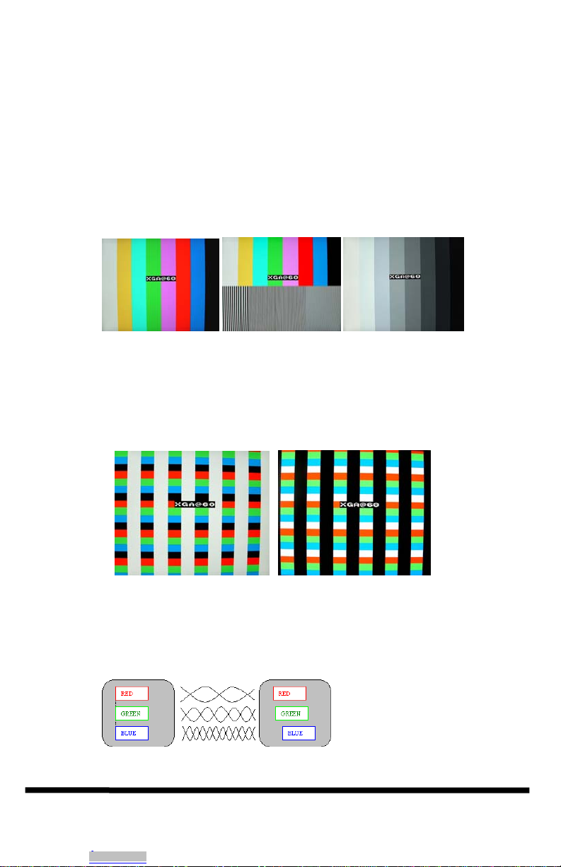
output resolution and refresh rate settings. Among the available 28 test patterns
are: color bar, multi-bust, circle, and crosshatch.
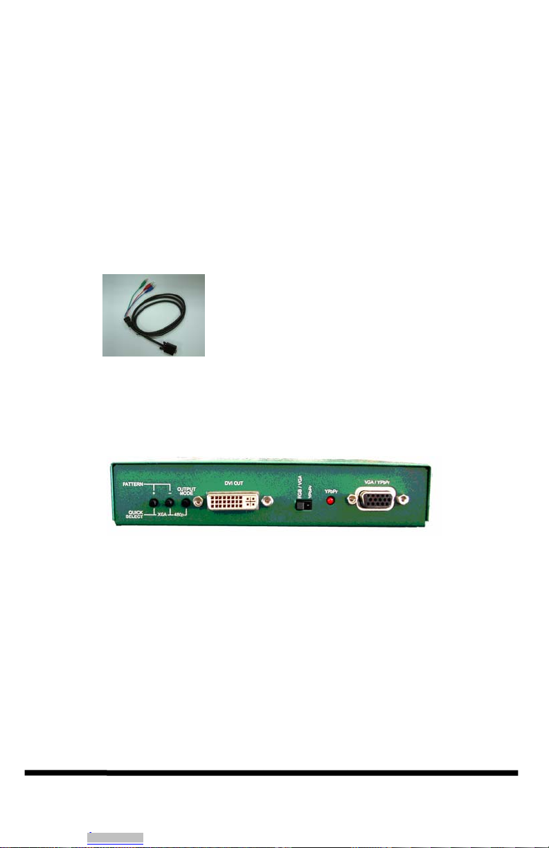
The Model 72-7985 comes in a sturdy metal case and it includes DVI, VGA,
and VGA-to-Component cables to handle most high-end testing and
installation requirements. It is ideal to use with LCD, plasma, CRT
monitors, and projectors that are equipped with PC, Component, or DVI inputs.
The addition of MCM Model 24-9316 adaptor cable (available separately) also
allows testing of monitors with HDMI inputs.
1.2 Features
•VGA, Component, and DVI/ video test pattern generator in one
compact, rugged housing.
•Programmable PC output resolutions from 640x480 to 1280x1024
(VGA/SVGA/XGA/SXGA)
•Programmable HDTV output resolutions from 480p to 1080i (480i
576i 480p 567p 720p 1080i)
•28 typical and custom video test patterns (both static and dynamic)
•Easy-to-use push-button OSD menu control
•Includes all cables required
•Packaged in highly portable EMI shielded enclosure
Downloaded from Arrow.com.Downloaded from Arrow.com.Downloaded from Arrow.com.Downloaded from Arrow.com.Downloaded from Arrow.com.

2. Installation
1. Plug the supplied AC adapter to the POWER input connector located on
the rear of the unit. To avoid risk of possible damage, use the supplied
adapter only. The green LED indicator will light, indicating the unit is
powered.
2. Included in the package are all necessary cables: DVI cable, VGA cable,
and HD15 to component Cable (shown below). For testing HDMI
connections, an optional cable (MCM #24-9316) may be purchased
separately.
3. Operation
¾The front panel of the unit is pictured below:
¾The two output connectors, DVI OUT and VGA/YPbPr, are
simultaneously active when the unit is on.
¾The VGA output serves two purposes: ▪Standard RGBHV VESA signals,
similar to that of most personal computers ▪YPbPr output, similar to the
Red/Blue/Green component video High Definition Television (HTVD)
signals. The output mode is determined by the slide switch immediately
left of this connector.
¾The red LED indicator, next to the slide switch, illuminates when the
output is one of the standard HDTV resolutions AND the slide switch is in
YPbPr mode.
© Copyright 2005, Tenma Test Equipment. All rights reserved.
405 S. Pioneer Blvd. Springboro Ohio 45066
Downloaded from Arrow.com.Downloaded from Arrow.com.Downloaded from Arrow.com.Downloaded from Arrow.com.Downloaded from Arrow.com.Downloaded from Arrow.com.

¾Operate requires simple selection from three push-button switches. One
button scrolls through all available resolutions and refresh rates (labeled
OUTPUT MODE). The other 2 buttons (labeled + and -) are used to
select the 28 available test patterns.
¾As an alternative to scrolling through all resolutions, you may quickly
“jump” to known resolution/refresh rates by simultaneously pressing two
buttons. Pressing the left two jumps directly to XGA at 60 Hz. Pressing
the right two jumps directly to 480p (a standard HDTV mode).
¾Note that in HDTV modes, the DVI OUT will always provide the proper
signal. The VGA (HD15 pin) connector will provide Component Video
(with sync on Y) if the slide switch is in the YPbPr position. In the RGB
position, this connector provides standard PC format VGA output.
¾The following chart lists the output resolutions in the order that the Mode
button scrolls. The on screen display will indicate this mode.
PC Resolutions
VGA 640 X 480 @ 50/60/72/75/85 Hz
SVGA 800 X 600 @ 50/56/60/72/75/85 Hz
XGA 1024 X 768 @ 50/60/70/75/85 Hz ---- (Quick Select)
WXGA 1280 X 768 @ 50/60 Hz
SXGA 1280 X 1024 @ 50/60 Hz
HDTV Resolutions
480P 720 X 480 @ 50/60 Hz ---- (Quick Select)
576P 720 X 576 @ 50/60 Hz
720P 1280 X 720 @ 50/60 Hz
1080i 1920 X 1080 @ 50/60 Hz
Downloaded from Arrow.com.Downloaded from Arrow.com.Downloaded from Arrow.com.Downloaded from Arrow.com.Downloaded from Arrow.com.Downloaded from Arrow.com.Downloaded from Arrow.com.

¾The (+) and (–) buttons select from 28 different video test patterns.
Standard patterns: ▪Color bars ▪Color bar and Multi-burst on same
screen ▪Grey-scale ▪Checkerboard ▪Circle ▪Crosshatch Dynamic
patterns: ▪Full screen smooth fade from black to full white
▪Checkerboard which alternates white and black squares approximately
once per second (this pattern may be good to test compression artifacts if
the video is going to be compressed for lower bandwidth transmission in
some future product).
¾There are 2 patterns with red, green and blue horizontal bars over white
and black background. This is ideal for video distribution testing,
especially over long cable runs. The high frequency loss in the long cable
runs will cause the color of the horizontal bars to smear to the right. MCM
Electronics offers several models of high quality video amplifiers and
extenders which have provisions for compensating for these losses.
The same 2 patterns are also useful when sending video over UTP cable,
such as Cat5, Cat5E or Cat6, both for the high-frequency loss and skew
compensation. The right and left edges of the RGB bars should line up
vertically. This pattern provides convenient means for making this
adjustment.
© Copyright 2005, Tenma Test Equipment. All rights reserved.
405 S. Pioneer Blvd. Springboro Ohio 45066
Downloaded from Arrow.com.Downloaded from Arrow.com.Downloaded from Arrow.com.Downloaded from Arrow.com.Downloaded from Arrow.com.Downloaded from Arrow.com.Downloaded from Arrow.com.Downloaded from Arrow.com.

Operation Summary
Repeatedly pressing the OUTPUT MODE button changes the
resolution. The on screen display will indicate the resolution and
refresh rate settings
NOTE: It is possible to set the output resolution to one that is not
supported by the connected monitor. In this case you my not get a
readable screen. Continue pressing the OUTPUT MODE button until
a compatible format is obtained, or use the two-button “QuickSelect”
combination to immediately jump to a known resolution.
To change the test pattern press the + or – keys.
To get analog high resolution component video output, at the HD15
connector (instead of VGA), slide the switch to YPbPr and press the
480p “QuickSelect”. The LED will turn on to indicate that there is a
valid component output signal present.
NOTE: If the LED is not on, this indicates improper analog
component output! Either the output MODE is not at one of the
HDTV settings, or the slide switch is not in correct position.
NOTE: The DVI connector outputs all available resolutions (both PC
and HDTV)
Once output resolution and pattern have been selected, for a period of
eight seconds, the unit will remember the setting when powered off.
The next time the unit is used, it will power on to the same setting.
Downloaded from Arrow.com.Downloaded from Arrow.com.Downloaded from Arrow.com.Downloaded from Arrow.com.Downloaded from Arrow.com.Downloaded from Arrow.com.Downloaded from Arrow.com.Downloaded from Arrow.com.Downloaded from Arrow.com.

4. Troubleshooting
If your monitor goes blank or says “mode not supported”
It is possible to set the output resolution to one not supported by the connected
monitor. In this case you may not get a screen. Either continue pressing the
OUTPUT MODE button, as it eventually scrolls through all the available
outputs in a circular fashion, or use the two–button “QuickSelect” combination
to immediately jump to a known output.
If you are certain the unit is malfunctioning
Do not open or try to repair the unit yourself. There are no customer repairable
items in the unit and you will void your warranty by doing so. Contact MCM
Customer Service at 1-877-626-3532.
Shipping and Packaging
If you need to transport or ship your converter:
• Package it carefully. We recommend that you use the original container.
• Before you ship the unit back to MCM, contact us to get a Return
Material Authorization (RMA) number.
© Copyright 2005, Tenma Test Equipment. All rights reserved.
405 S. Pioneer Blvd. Springboro Ohio 45066
Downloaded from Arrow.com.Downloaded from Arrow.com.Downloaded from Arrow.com.Downloaded from Arrow.com.Downloaded from Arrow.com.Downloaded from Arrow.com.Downloaded from Arrow.com.Downloaded from Arrow.com.Downloaded from Arrow.com.Downloaded from Arrow.com.

5. Specifications
Compliance CE; FCC Part 15 Subpart B Class A, IC Class
Standards PC (RGBHV): VGA, SVGA, XGA, SXGA video.
HDTV (YPbPr): 480P, 576P, 720P, 1080i
DVI: All of the above
Interfaces
Supported Analog Video: VGA, and YPbPr
Digital Video: DVI –I Single link
Video Level 0.7 volts peak-to-peak, on RGB, 3 v on H & V
1vp-p on Y signal, 0.7 vp-p on Pb&Pr in YPbPr mode
Connectors HD15 for VGA and Y/Pb/Pr output
29 pin female DVI connector
Temperature
Tolerance Operating: 32 ~122°F (0 ~ 50°C);
Storage: –40 ~ +185°F (–40 ~ +85°C)
Enclosure Steel
Power
Requirements 5VDC, 1.5A max (center tip positive)
AC adaptor included
Dimensions 1.2” (H) x 7" (W) x 7" (D)
Downloaded from Arrow.com.Downloaded from Arrow.com.Downloaded from Arrow.com.Downloaded from Arrow.com.Downloaded from Arrow.com.Downloaded from Arrow.com.Downloaded from Arrow.com.Downloaded from Arrow.com.Downloaded from Arrow.com.Downloaded from Arrow.com.Downloaded from Arrow.com.
Table of contents
Other Tenma Test Equipment manuals

Tenma
Tenma 72-2650 User manual

Tenma
Tenma 72-7910 User manual

Tenma
Tenma 72-9400A User manual

Tenma
Tenma 72-2680 User manual

Tenma
Tenma 72-2665 User manual

Tenma
Tenma 72-17175 User manual

Tenma
Tenma DSO Series User manual

Tenma
Tenma 72-3575 User manual

Tenma
Tenma 72-2650 User manual

Tenma
Tenma 72-6694 User manual