ELABO 92-4A User manual

Operating manual
Leakage current tester
92-4A / 92-4D / 92-4E

2
Leakage current tester 92-4A / 92-4D / 92-2E
Content
1 INTRODUCTION ....................................................................... 7
1.1 General information ................................................................... 7
1.2 Abbreviations and symbols........................................................ 8
1.3 Brief description of the tester ..................................................... 8
1.4 Technical main data ................................................................ 10
1.5 Name plate .............................................................................. 10
2 SAFETY REGULATIONS.........................................................11
2.1 Signs of safety and warning regulations ...................................11
2.2 Warranty ...................................................................................11
2.3 Useasperspecicationsandexclusionofliability .................. 12
2.4 General rules of conduct and safety regulations ..................... 12
2.5 Further notes ........................................................................... 13
3 MAKE READY......................................................................... 14
3.1 Transport and installation ........................................................ 14
3.2 Environmental conditions......................................................... 14
3.3 Mounting in enclosure or rack.................................................. 14
3.4 AC power supply...................................................................... 15
3.5 Connectionforexternalsupplyoftestobject .......................... 16
3.6 Connection of the interfaces .................................................... 17
3.6.1 Connection of the CAN-interface (Option)........................... 17
3.6.2 Connection of the RS 232-interface ................................... 17
3.6.3 Connection of the printer ..................................................... 17
3.7 Switch on ................................................................................. 18
3.8 Display division general ........................................................... 19
3.9 Password protection ................................................................ 20
3.9.1 Password "Test menu"......................................................... 20
3.9.2 Password "Test parameter" ................................................ 20
3.9.3 Password "Instrument settings"........................................... 20
3.10 Change language .................................................................... 21
4 MENU SYSTEM ...................................................................... 22
4.1 General .................................................................................... 22
4.1.1 Move cursor......................................................................... 22
4.1.2 Display of important parameters.......................................... 22
4.2 Main menu ............................................................................... 23
4.3 Menu Manual test .................................................................... 24
4.4 Menu Automatic test ................................................................ 25
4.5 Menu Set test parameters ....................................................... 26
4.5.1 Basic settings ...................................................................... 27

3
Leakage current tester 92-4A / 92-4D / 92-2E
4.5.2 Parameter of Leakage Current Measuring .......................... 31
4.5.3 Select Parameter Block....................................................... 35
4.5.4 Save Parameter Block......................................................... 35
4.5.5 Erase Parameter Block ....................................................... 36
4.6 Instrument settings .................................................................. 37
4.6.1 Select language................................................................... 39
4.6.2 Set Date and Time............................................................... 40
4.6.3 Adjustdisplay ..................................................................... 42
4.6.4 Setting Serial Interface ........................................................ 43
4.6.5 Printer Settings.................................................................... 44
4.6.6 Buzzer settings.................................................................... 45
4.6.7 Change Passwords ............................................................. 46
4.6.8 Settings(autom.adjustment)............................................... 48
4.6.9 Device information 1 and 2.................................................. 49
5 TEXT INPUT............................................................................ 50
5.1 Enter numerical values ............................................................ 51
6 TESTING ................................................................................. 52
6.1 Connecttestobject .................................................................. 52
6.2 Manual leakage current test .................................................... 53
6.3 Automatic leakage current test ................................................ 55
7 MAINTENANCE AND ATTENDANCE .................................... 57
7.1 Exchangeoffuses ................................................................... 57
7.2 Attendance of the chassis........................................................ 57
8 TROUBLE SHOOTING ........................................................... 58
8.1 Error message ......................................................................... 58
9 SPECIFICATIONS................................................................... 60
9.1 Leakage current tester 92-4A .................................................. 60
9.2 Leakage current tester 92-4D / 92-4E ..................................... 61
I TESTER INSIDE...................................................................... 63
I.i 1-phase devices 92-4A, - 4E; - 4G ......................................... 63
I.ii 3-phase device 92-4G ............................................................. 64
II MEASURING CIRCUITS ........................................................ 65
II.i 1-phase Connection principle .................................................. 65
II.ii Measuring Circuits (Connection principle) ............................... 67
III PIN-ASSIGNMENT.................................................................. 71
III.i X13/X14 9pole DSUB CAN-Bus-Interface ............................... 71
III.ii X15 9pole DSUB RS232-Interface .......................................... 71

4
Leakage current tester 92-4A / 92-4D / 92-2E
IV MODIFICATIONS .................................................................... 72
IV.i Externalsupplyviamultipleconnector .................................... 72
IV.ii Test unit with automatic voltage regulation (optional feature) . 73
V MEASUREMENT SYSTEM..................................................... 74
VI BASIC TEST MODES ............................................................ 75
VI.i Basic test modes to EN 60601. .............................................. 75
VI.ii Measurement circuits according EN 60990-1.......................... 75
VI.iii Basic test modes according EN 60335, IEC 60335
.................. 76
VI.iv Basic test modes according EN 60065................................... 77
VI.v Measuring of contact currents according EN 60950/EN 6074578
VI.vi Measuring of contact currents according EN 60745................ 79
VI.vii Measuring of contact currents according EN 60598................ 80
VI.viii Special standard uninterruptable Measurement at luminaries
EN 60538_VDE ...................................................................... 81
VI.ix MeasuringofcontactcurrentsaccordingUL250/UL471....... 82
VI.x Basictestmodes3~UIT's ....................................................... 83
VI.x.i 3~MeasuringofleakagecurrentaccordingEN61010 ..... 84
VI.x.ii 3~MeasuringofleakagecurrentaccordingEN60950 ... 84
VI.x.iii Switchingtablefor3~testobjects...................................... 85
VII FIRMWARE BUG 92-4A/-D/-E/-G ........................................... 86
5
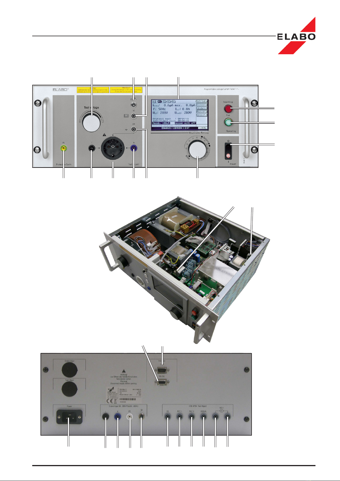
X14 X15
X1 X4.1 X4.2 X4.3 F3 X7 X8 X9 X10 X11 X12
S2/HA2
S3/H3
S1/H1
F1a F1
X6 X3.1 X2 X3.2 X3.3 S4
T1 F2 X5 A7
Leakage current tester 92-4A / 92-4D / 92-2E
6
Leakage current tester 92-4A / 92-4D / 92-2E
No. Equipment Function
A7 Display Graphic display 240x 128 Pixel
indication of menu and measurement values
S1/H1 Switch / glow lamp Mains switch with indication lamp
F2 Automatic circuit breaker 15 A Output fuse, power supply of test object
S2/H2 Illuminated push button (red) Acknowledge faults / interrupt leakage current test
S3/H3 Illuminated push button (green) Start test / line shift for text input mode
S4 Rotary encoder Entry system with push button menu selection/parameter settings
T1 Variable-ratio transformer Adjust output-/test voltage at X2 and X3
X2 Schuko socket Connection for test objects with plug (Attention: at PE-fault simulation, the
PE is discontinuous by the device)
X3.1 Safety lab terminal (black) l1 connection for test objects with loose cable ends
X3.2 Safety lab terminal (blue) n connection for test objects with loose cable ends
X3.3 Safety lab terminal (white) pe connection for test objects with loose cable ends (Attention: at PE-fault
simulation, the PE is discontinuous by the device)
X5 Safety lab terminal (white) vi connection of the housing for test objects with protective insulation
MD2-1 second measurement system (option feature)
X6 Safety lab terminal (yellow/
green)
PE direct protective earth from the mains supply
(can not be switched off)
Inside
F1 Fine wire fuse T 10.0 A Main fuse
F1a Fine wire fuse F 2.0 A Main power supply fuse of control unit
Rear side
F3 Automatic circuit breaker 15 A Input fuse of external test object supply (X4)
X1 Power supply connector Mains supply / internal power supply
X4.1 Safety lab terminal (black) L connection of external test object power supply (input)
X4.2 Safety lab terminal (blue) N connection of external test object power supply (input)
X4.3 Safety lab terminal (white) PE reference point of external test object power supply (input) for
measurement
X7 Safety lab terminal (grey) FE measurement input "Common return connection of test object" (for
medical equipment according to EN 60601-1 only)
X8 Safety lab terminal (grey) PAT1 measurement input "patient connection 1"
(for medical equipment according to EN 60601-1 only)
X9 Safety lab terminal (grey) PAT2 measurement input "patient connection 2"
(for medical equipment according to EN 60601-1 only)
MD2-2 second measurement system (option feature)
X10 Safety lab terminal (grey) Signal auxiliary voltage for signal input-/ output unit (for medical
equipment according to EN 60601-1
X11 Safety lab terminal (grey) MS II not connected
X12 Safety lab terminal (grey) MS II not connected
X13 D-SUB 9pole (male) CAN-bus connector (input)
X15 D-SUB 9pole (female) RS 232-interface - printer / PC control

7
Leakage current tester 92-4A / 92-4D / 92-2E
INTRODUCTION
1 INTRODUCTION
The security of all persons coming into contact with the leakage current
tester is decisively dependent upon the mastery of the unit. Therefore:
Read the operating instructions before the rst putting into opera-
tion!
1.1 General information
the operating instructions enable the user to become familiar with the tester
anditsapplicationpossibilitiesandtouseitasperthespecicationsbefore
therstoperation.Theycontainimportantinformationwhichguaranteea
functional, economic and safe operation and have to be always available
at the operational place of the tester.
The operating instructions are not only an indispensable lead-in for op-
erators who have to be instructed from the very beginning but they also
contain useful tips, information and suggestions for the skilled operator.
They are a necessary reference book for all operators. By reading the
operating instructions
• dangers are avoided
• sequences of operations are optimized and accelerated
• cost of repair and times of standstill are minimized
• reliability and service life are increased
The operating instructions should also be attentively read by the unit owner
and the person responsible for the operation. Particularly with regard to
transport and installation as well as guarantee questions.
In chapter 2 important information regarding security and risks are given
which prepare you for danger situations that may arise. During operation
it is unfortunately too late to read again. In addition to this please note the
following rule:
Cautious and careful working is the best protection from acci-
dents!
The testing quality of the unit is decisively dependent on maintenance and
attendance. Regular activities concerning maintenance and attendance
are described in these operating instructions. We have pleasure in sup-
porting you in case of necessary repairs and supply you with the original
spare parts.
If you have any questions after reading the operating instructions the
ELABO HOT-LINE (Telephone +49 7951/307-202) is at your disposal for
further details.
For better use of the operating instructions the cover page can be opened
out. Through this the illustration of the front or rear panel of the unit is
always visible for the user while reading the operating instructions.
8
SO
•1
•
Leakage current tester 92-4A / 92-4D / 92-2E
INTRODUCTION
1.2 Abbreviations and symbols
extraEquipment,itdoesnotbelongtothestandardequipment
Enumeration , the recommended order has to be observed
Enumeration
CAUTION ELECTRIC HIGH VOLTAGE - DANGER TO LIFE!
Danger Zone for life of operator and third persons! - see chap. 2.1
Danger for the unit! - see chap. 2.1
Information for an effective and economic mode of operation - see chap. 2.1
1.3 Brief description of the tester
the test unit is intended for measurement of the leakage current of electrical
equipment(e.g.householdequipment,medicalequipment,lightxtures)
which, according to the relevant VDE, EN or IEC safety regulations must
be tested.
The unit can be equipped in different construction stages for measurement
of the leakage current of single-phase appliances according to different
regulations in operation and single fault case. The corresponding optional
feature (e.g. required the measurement circuit) must be ordered in addition
to the test instrument.
An overview of the standards and associated basic circuits is includ-
ed in the appendix.
If you need:
- test methods according to other regulations or standards,
- different measuring-circuits,
please contact ELABO.
Note: Depending on the equipment in the LC-tester it is possible to carry
out leakage current measurement according to above mentioned stand-
ards. Depending on the manufacturing date of the equipment the hard and
software corresponds to the valid norms and standards.
The unit is operated by means of the rotary encoder S4 via the display
menu. All settings of the devices and test parameter are carried out there.
The menu items and parameters which are not supported by the unit ver-
sion or construction stage are not visible or selectable.
There are manually or automatically test runs possible. For storage of test
parametersitispossibletocreateparameterblocks.Maximal200different
parameter blocks can be stored.
The unit can either be controlled via the front panel components or the
interface (CAN-Bus or RS232-interface) by using a PC. To this, ELABO
9
Leakage current tester 92-4A / 92-4D / 92-2E
INTRODUCTION
Illustr. 1.1: LC-
tester 92-4E
for using in
automatic test
systems
offers a special software for control, administration and evaluation of the
measurements. The operating devices at the front-panel are not active
duringcontrolviainterface(exceptforthered„Reset/Stop“buttonand
Off-switch). For faster measurements, the display of the LC-tester is
switched off by the PC-software. The indication of the measurement data
isexclusivelycarriedoutatthePCscreen.
For the output of test protocols a serial printer can be connected to the
unit. For control via the RS 232 interface the protocol printer has to be
connected to the PC.
Toprotectagainstunauthorizeduseand/ormodicationoftest-/device
parameters a 3-level password protection can be activated (see Pass-
words chapter 3.9).
The power supply of the item under test can be carried out through the
test unit (internally) or by means of a separate power supply connected
tothetestunit(externally).
The unit is designed as a system module 19"/ 4HU (standard unit), 19"/6
HU or 19"/8HU, depend on the technical requirements.
92-4E LC-tester for using in automatic test systems: The leakage
current tester is delivered also as a variant without display (VIT controler
system). This type is built for using in automatic test systems. The control
of the device is completely carried out via the control computer of the
test system. The commands for the control of the device contains the
description of the remote control of the 92-4A / -4D / -4E.
The description of the menus is helpful for the programming of the remote
control of the device.
10
Leakage current tester 92-4A / 92-4D / 92-2E
INTRODUCTION
1.4 Technical main data
Operating temperature range: 10oC . . .50oC
Air humidity: 25 - 75%
Power supply: 230 V +/- 10% / 49 - 61 Hz
Mainsfuse: newirefuseT10A(insidethehousing)
Measurement range: 100 µA / 1 mA / 10 mA
Leakage current limits: programmable 5 µA .... 10 mA
Dimensions (standard housing): 19" / 4U high, 360 mm deep
Weight: approx.31kg
Supply(internal/external):
see Chapt. 9 "SPECIFICATION"
1.5 Name plate
ELABO Leakage current tester 92-4A / 92-4D / 92-4E
The name plate is located on the rear panel of the tester.
Illustr. 1.2: ELABO Name plate for device 92-4A
SN. 0000042483
ELABO GmbH
Rossfelder Str. 56
D-74564 Crailsheim
Telefon: +49 7951 307-0
Telefax:+497951307-65
Nennspg. V
~
Nennstrom A
Typ
Baujahr
230 V ; 49 - 61 Hz
16.0 A
92-4A
2003
11
Leakage current tester 92-4A / 92-4D / 92-2E
Safety Regulations
2 SAFETY REGULATIONS
Before working with the leakage current tester the operating instructions
and all enclosures must have been attentively read and understood by all
persons operating the tester. The tester may be operated by trained and
skilled staff only.
When operating the tester voltages up to 300 V can occur. In dealing
with voltage there is danger to life ! Therefore ELABO has equipped
the testing units with all necessary safety devices when using them as per
thespecicationsinordertoprotecttheoperatorfromappearingrisks.
CAUTIOUS AND CAREFUL WORKING IS THE
BEST PROTECTION FROM ACCIDENTS !
2.1 Signs of safety and warning regulations
Danger Zone
Electric Voltage - danger to life !
IN DEALING WITH VOLTAGE THERE IS DANGER TO LIFE!
This sign warns of a danger zone through electric voltage. It is situated at
all working cycles where life of the operator and other persons is en-
dangered. It is situated at working and operating procedures which have
to be observed accurately in order to prevent endangering of persons or
the tester by electric voltage.
Pay attention to the information and
act very careful in these situations.
Also pass all safety regulations
on to other operators.
Caution !
Thissignsigniesdanger for the tester in case of non-observance of
instruction.
Information !
Thissignsigniesthatamoreeffectiveandmoreeconomicuseofthe
tester is possible.
2.2 Warranty
Claims for warranty can only then be asserted when the terms of warranty
included in the general terms of sale and delivery are observed. Further-
more, the terms of the operating instructions have to be observed.

12
Leakage current tester 92-4A / 92-4D / 92-2E
Safety Regulations
2.3 Use as per specications and exclusion of liability
Theleakagecurrenttesterhastobeusedasperthespecicationsonly
for the intended tests. Every use beyond is considered as not according
tothespecications.ELABOdoesnotacceptanyliabilityfordamages
resultingfromthis,theoperatorexclusivelycarriestherisk.Itisalsonec-
essaryfortheuseasperthespecicationsthattheinformationgivenin
these operating instructions is observed.
The device and its components have been developed and constructed for
theapplicationintheindustrialeld.AccordingtoDINEN55022ITEthis
unit represents a system of the class A. Neither the leakage current tester
as a whole or the single components of it may be employed in another
environment. In case of non-observance of this information ELABO does
not accept any liability for appearing malfunctions and damages resulting
from this.
These operating instructions and all enclosures must have been attentive-
ly read and understood by all operators before working with the leakage
current tester. The leakage current tester has to be operated by trained
and skilled staff only.
The device may not be changed regarding construction and safety tech-
nology.EveryalterationneedstheexpressassentofELABO.
Unauthorizedmodicationsattheleakagecurrenttesteraswellasthe
use of spare parts, accessories and extra equipments which have not
beencontrolledandreleasedbyELABOcanhaveanegativeinuence
on the function and features of the leakage current tester. ELABO does
not accept any liability for damages resulting from this.
ELABO does not accept any liability for damages arising by non-ob-
servance of the operating instructions or by negligence of duty of care
during the transport, installation, handling, operation, attendance and
maintenance or during repair of the unit even if these duties of care are
not particularly pointed to in the operating instructions.
2.4 General rules of conduct and safety regulations
The leakage current tester was built according to the state of art and
approved safety regulations. Nevertheless, there might arise danger to
life of the operator or third persons respectively damages at the tester or
other material goods.
The leakage current tester has to be operated in workmanlike condition
onlyandaccordingtothespecicationsunderobservanceoftheoperating
instructions. Faults impairing the safety have to be cleared immediately.
The person responsible for the operation has to attend to that the staff
charged with work at the tester must have read and understood the oper-
ating instructions before commencement of work. The person responsible
for the tester operation is obliged to always operate the tester in perfect
condition only and to instruct the service staff to use the unit as per the
specications.

13
Leakage current tester 92-4A / 92-4D / 92-2E
Safety Regulations
The operating instructions have to be always available at the operational
place of the tester. Incomplete or illegible operating instructions have to
be replaced immediately. Of course, we are pleased to be of help to you
in this respect.
In addition to the operating instructions legal, generally valid and other
obligatory regulations for accident prevention and environmental protection
have to be observed.
2.5 Further notes
Attention:
During leakage current measurements the enclosure of the item
under test can be voltage-carrying. Therefore, it is necessary to
take action to prevent a touching of the item under test during the
measurement ( separate test room, barring off, warning signs ...)
Attention: Before a leakage current measurement is conducted make
sure that the protective earth conductor connection is in good order!!
Therefore, prior to the leakage current measurement a protective
earth continuity test must be carried out under all circumstances.
Attention:
The unit is rather heavy (see chap. 1 "Technical Main Data "). Therefore
it is necessary, to take suitable actions during installation and removing.
14
Leakage current tester 92-4A / 92-4D / 92-2E
Make ready
3 MAKE READY
3.1 Transport and installation
The device is delivered completely packed and may only be taken out off
the package directly at the operational place.
If an intermediate storage is necessary, a dry storage place must be
chosen.
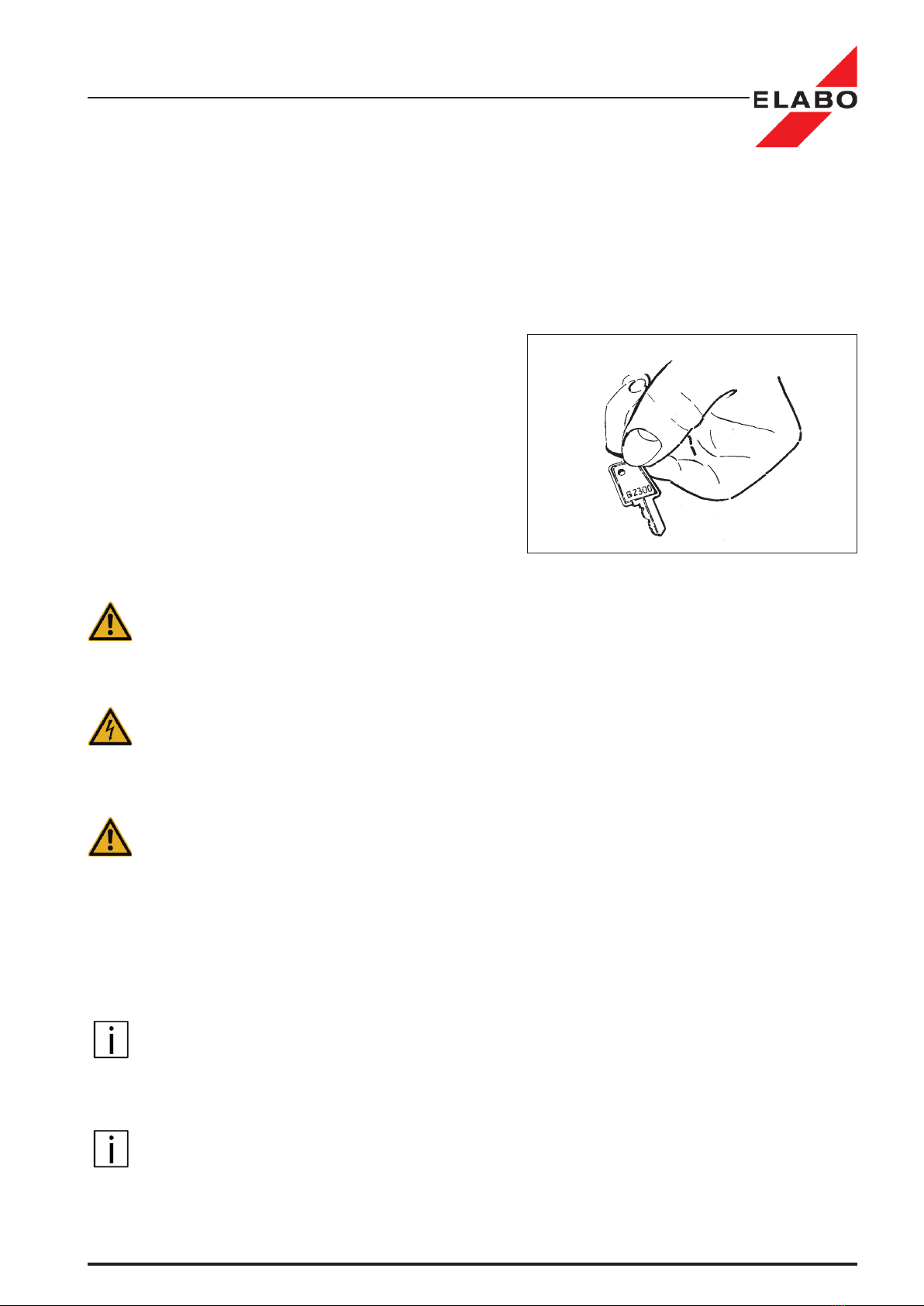
The facility is protected against
unauthorized operation by a
key switch (S1) or by pass
word. ).
After unpacking, the keys have
to be immediately handed over
to the person responsible for
the operation and have to be
kept inaccessible for other em-
ployees by him.
Note:
The tester can be integrated into a suitable industrial rack with 19” inser-
tions. If this is not provided the operational area has to be plane and clean.
The tester has to be secured against unintentional displacement.
Attention:
Thedeviceisheavy(seecape.1„technicalmaindata“).Thereforesuitable
precautions must be taken to avoid accidents in front of the installation
or consolidation.
Prerequisite:
The operational surface has to be suited to the weight of the tester (see
chapt. 1 "Technical Main Data") and provide a safe support for the unit at
any time.
When installing the tester pay attention that the information and safety
signs at the instrument are not covered.
3.2 Environmental conditions
TheLeakagecurrenttestermustnotbeoperatedinadusty,inammable,
aggressive or humid environment. The permissible values of temperature
and humidity are listed in chapter 1.4 ´Technical Main Data´.
3.3 Mounting in enclosure or rack
Note: Push the device carefully into the rack until the stop. Do not tilt the
unit while pushing it in.
After pushing in the unit into the enclosure, the unit must be fastened by
4 screws, located on the front-panel.
Illustr. 3.1: Key (S1) of the tester

15
Leakage current tester 92-4A / 92-4D / 92-2E
Make ready
The operation of the unit without being fastened is not permitted!
The unit should not be operated without being put into an enclosure or rack.
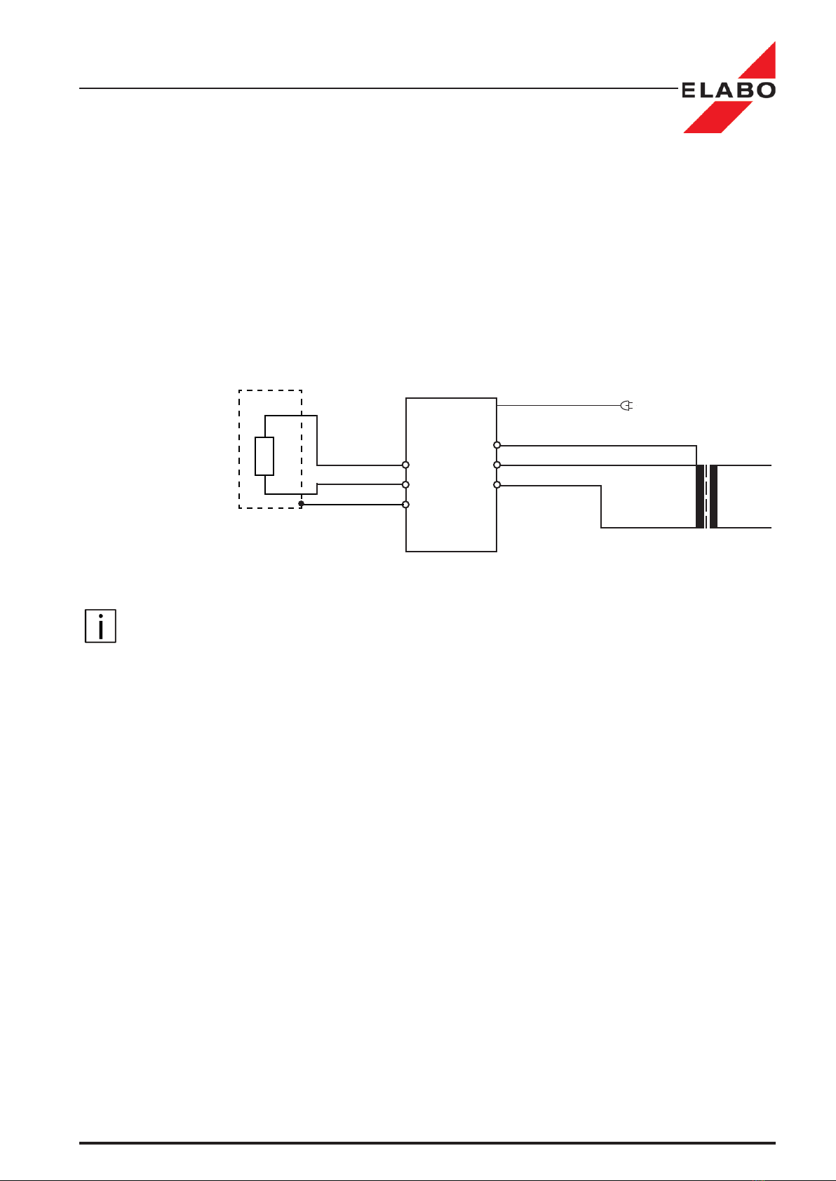
3.4 AC power supply
The power supply of the unit is by means of a three pin plug.
AC power supply 230 V / 49 - 61 Hz, fusing 16 A.
Note:
The polarity check of the mains plug is possible and active.
92-4A
Illustr. 3.2: Principleconnectionforinternalsupplyofthetestobject
Mains plug X1
l
n
pe
Testobject
X3.1 - 3.3
16
Leakage current tester 92-4A / 92-4D / 92-2E
Make ready
3.5 Connection for external supply of test object
Theconnectionforanexternalsupplyiscarriedoutbymeansofsafety
lab terminals X4.1, X4.2 and X4.3 located at the rear of the unit.
Externalsupply:50...280V/50...400Hz,fusing15A.
Theconnectionprincipleisrepresentedowingly.
Note:
The PE-connection has to be connected to the appropriate reference
potential.
Note:
Atexternalsupplyofthetestobjectthepolaritycheckofthemainsplug
is not active.
PE
N
L
92-4A
Illustr. 3.3: Principleconnectionforexternalsupply1~NPE
Mains plug X1
l
n
pe
Testobject
e.g. isolation transformer
forexternalsupply
X4.1-4.3
X3.1 - 3.3

17
Leakage current tester 92-4A / 92-4D / 92-2E
Make ready
3.6 Connection of the interfaces
3.6.1 Connection of the CAN-interface (Option)
PlugintheCAN-BUS-interfacecableintothe9poleD-SUB-jackX13.
ThenextuserinthebussystemmustbeconnectedtoX14.
If the control shall be carried out via the CAN-interface then the parameter
of the interface must be set in the menu to " Equipment settings" CAN-Bus.
Note:
If the LC-Tester is the last unit at the CAN-bus system, then the bus has
to be assigned to X14. The CAN-bus must be supplied with 10 -12 V DC.
3.6.2 Connection of the RS 232-interface
Plugintheserialinterfacecableintothe9poleD-SUB-jackX15.Forcon-
nection to the PC a so-called "Zero modem-cable" has to be used.
If the control shall be carried out via the RS232-interface then the pa-
rameter of the "RS232-interface" must be set in the menu to " Equipment
settings-RS232" (chapt. 4.6.4).
Note:
If the leakage current tester is controlled by a PC via the RS 232-inter-
face, then the protocol printer has to be connected to the PC. In menu
"Equipment settings - Print" (Chapt. 4.6.5) the printer must be deactivated.
3.6.3 Connection of the printer
A protocol printer can be connected to the RS 232 interface. If a printer is
connected then the parameter "Printer setting" in the menu "Equipment
settings-Printing" (Chapt. 4.6.5) must be set.
Use a so-called "Zero modem-cable" and if necessary a Serial/Parallel
converter.

18
S4
S1
Leakage current tester 92-4A / 92-4D / 92-2E
Make ready
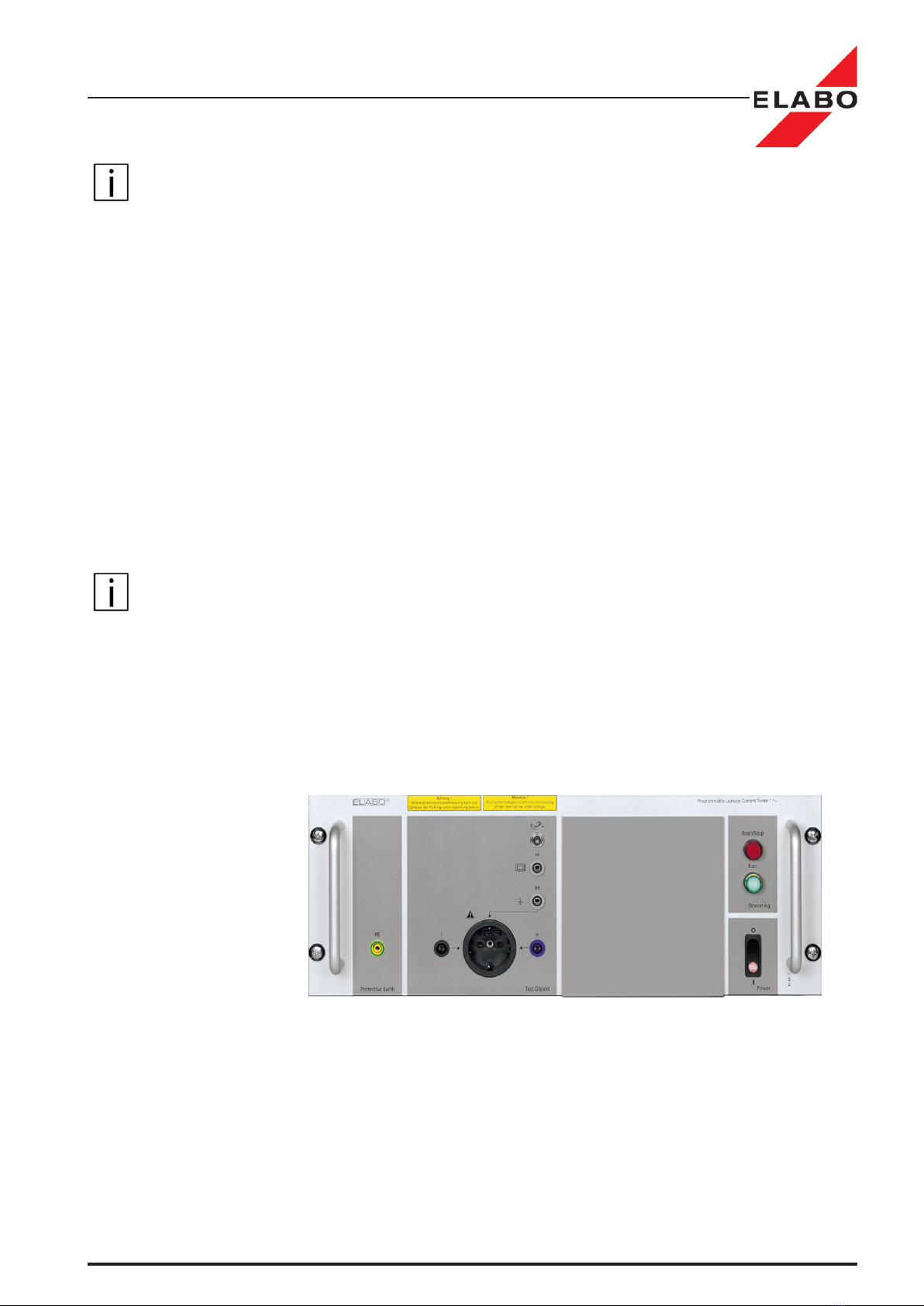
3.7 Switch on
Prerequisite:
The device is connected according to chapter 3.4 or 3.5.
• Operate the switch S1 to position "I".
The mains pilot lamp H1 lights up and the display shows after a short
run- up time:
- the main menu (password level 1 not active - factory setting)
- the password inquiry for level 1 (password level 1 active)
• Enter the password - see also Chapt. 3.9.
Check now if the mains plug X1 is connected correctly.
Proceed as follows:
• Select with rotary encoder S4 the menu item "Manual".
•ConrmbypressingrotaryencoderS4.
• Select with rotary encoder S4 "A1".
•ConrmbypressingrotaryencoderS4.
Mains plug plugged in correctly:
The leakage current measurement "A1" is offered to be started (Status line).
You can interrupt the test run and return to the main menu by operating
the red Reset-button.
Description of the main menu, see Chapter 4.
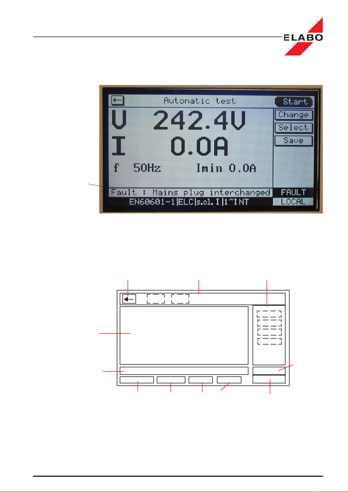
Mains plug not plugged in correctly (SCHUKO PLUG ONLY):
The buzzer sounds intermittent and the red reset keyboard ashes . The
fault is monitored in the display (see Fig. - next page).
• Operate the red Reset-button.
• Switch off the unit. Mains switch "Position 0".
• Pull out the plug, turn it by 180 ° and plug in again.
Illustr. 3.4: Front panel 92-4A
19
Leakage current tester 92-4A / 92-4D / 92-2E
Make ready
Return
Section for action keys in the test menus
or menu header line (heading)
Keys section to ac-
tivate the menu
Information section
of menu-driven op-
erations or actual
indication in the test
menu.
Ongoingstatustext
for menu prompt
and error indication
Fixedstatustextstodisplaytheparam-
eters of the actually loaded parameter
block (see Chapter 4.1.2)
Status display of the
control mode
Local / Remote
Status display
of the last test
results
Fault / Passed
Illustr. 3.5: Display division
Illustr. 3.6: Error message of incorrect mains plug
Status line:
Error message
• Switch on the unit. Mains switch S1 to "Position I" (see above).
3.8 Display division general

20
Leakage current tester 92-4A / 92-4D / 92-2E
Make ready
3.9 Password protection
The device includes a 3-layer password protection function. The pass-
word layers are separately from each other to activate or to deactivate.
The passwords for the layers are individually set able.
Password settings and activation see chapt. 4.6.7.
3.9.1 Password "Test menu"
Protection against an unauthorized use of the device.
Inquiry after switching on the device.
Factory setting "MESS"
3.9.2 Password "Test parameter"
Protection of the menu "Test parameter".
Inquiry after call the "Test parameter"- menu.
factory setting "PARAM"
3.9.3 Password "Instrument settings"
Protectionofthemenu„Instrumentsettings“.
Inquiryaftercallthe"„Instrumentsettings"-menu.
Factory setting "SETUP"
Password
"Test parameter"
Password
"Instrument set-
tings"
Illustr. 3.7: Password inquiry after switch on
Illustr. 3.8: Main menu - Password protection "level 1"
This manual suits for next models
2
Table of contents
Other ELABO Test Equipment manuals


