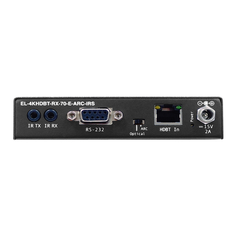
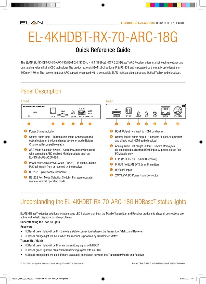
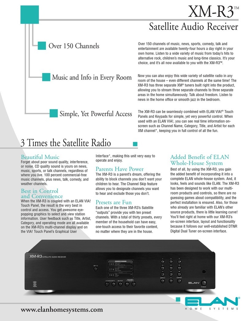
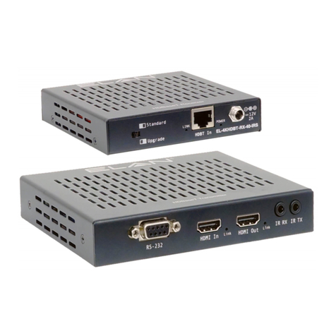
Elan XM-R3 User manual


© ELAN Home Systems 2005 • All rights reserved. i
XM-R3 Satellite Audio Receiver Preface
Preface
Purpose of This Manual
This manual provides step-by-step installation instructions and connection examples, along with basic user information for instal-
lation and ongoing use of the XM-R3 Satellite Audio Receiver. This manual is written for the installer and user of this equipment.
Organization
The following information is contained in this manual:
Safety Information
Chapter 1 Provides an introduction to ELAN Home Systems’ XM-R3™ Satellite Audio
Receiver, along with a system description and equipment specifications.
Chapter 2 Presents step-by-step instructions for installing the XM-R3 Satellite Audio
Receiver, XM Antenna and in-line amplifiers, and XM Radio activation informa-
tion, along with system connections such as IR, RS232, Digital Out and Audio.
Chapter 3 Describes front panel and hand-held remote control operations, along with IR
and RS232 control using ELAN Kepads and VIA! Touch Panels.
CAUTION: TO REDUCE THE RISK OF ELECTRIC SHOCK, DO NOT REMOVE
TOP COVER (OR BACK). NO USER-SERVICEABLE PARTS INSIDE. REFER
SERVICING TO QUALIFIED SERVICE PERSONNEL.
The lightning flash with arrowhead symbol within an equilateral triangle, is
intended to alert the user to the presence of uninsulated “dangerous volt-
age” within the product’s enclosure that may be of sufficient magnitude to
constitute a risk of electric shock to persons.
The exclamation point within an equilateral triangle is intended to alert the
user to the presence of important operating and maintenance (servicing)
instructions in the literature accompanying the appliance.
WARNING: TO PREVENT FIRE OR SHOCK HAZARD, DO NOT EXPOSE THIS APPLIANCE
TO RAIN OR MOISTURE.

ii © ELAN Home Systems 2005 • All rights reserved.
Preface XM-R3 Satellite Audio Receiver
Water and Moisture—
To reduce the risk of electric shock or fire, these appliances should not be used near water––for
example, near a bathtub, washbowl, kitchen sink, laundry tub, in a wet basement, or near a swimming pool.
Power Cord Protection—
Protect the power cord from being walked on or pinched particularly at plugs, convenience recep-
tacles and the point where they exit from the apparatus.
Telephones—
Avoid using a telephone (other than a cordless type) during an electrical storm. There may be a remote risk of
electrical shock from lightning. Do not use a telephone to report a gas leak if the leak is in the vicinity of the ELAN electronic equip-
ment because of risk of fire or explosion.
Cleaning—
Unplug the apparatus from the power outlet before cleaning. Use only a dry cloth to clean the apparatus.
Power Lines—
An outdoor antenna should be located away from power lines. When installing an outside antenna system,
extreme care should be taken to avoid touching power lines or circuits, as contact with them may be fatal.
Outdoor Antenna Grounding—
If an outside antenna or cable system is con-
nected to these audio products, be sure the antenna or cable system is grounded
so as to provide some protection against voltage surges and built-up static
charges. Section 810 of the U.S. National Electrical Code, and Section 54 of the
Canadian Electrical Code, provide information with respect to proper grounding of
the mast and supporting structure, grounding of the lead-in wire to an antenna dis-
charge unit, size of grounding conductors, location of antenna-discharge unit, con-
nection to grounding electrodes, and requirements for the grounding electrode. See
the grounding diagram (right).
Overloading—
Do not overload wall outlets and extension cords, as this could
result in fire or electric shock. Object and Liquid Entry—Never insert objects of any
kind through the openings of these appliances, as they may touch dangerous volt-
age points or short-out parts that could result in a fire or electric shock. Care should
be taken so that objects do not fall and liquids are not spilled into the appliance
through openings in the enclosure.
Servicing—Do not attempt to service these appliances yourself, as opening or removing covers may expose you to dangerous volt-
age or other hazards. Refer all servicing to qualified service personnel.
Damage Requiring Service—These appliances should be serviced by qualified service personnel when:
• A power supply connection or a plug has been damaged or
• If liquid has been spilled into the appliance or objects have fallen into the appliance or
• The appliance has been exposed to water or moisture or
• The appliance does not appear to operate normally or exhibits a marked change in performance or
• The appliance has been dropped or the enclosure damaged.
Replacement Parts—
When replacement parts are required, be sure the service technician has used replacement parts speci-
fied by the manufacturer or that have the same characteristics as the original part. Unauthorized substitutions may result in fire,
electric shock, or other hazards.
Safety Check—Upon completion of any service or repairs to this audio product, ask the service technician to perform safety
checks to determine that the audio product is in proper operating condition.
Lightning Storms—
Unplug this apparatus during lightning storms or when unused for long periods of time.
Attachments and Accessories—
Use only attachments/accessories specified by the manufacturer.
Cart, Stand, Tripod, Bracket or Table—
Use only with a cart, stand, tripod, bracket or table specified by the manufacturer,
or sold with the apparatus. When a cart is used, use caution when moving the cart/apparatus combination to avoid injury from tip
over.
Disconnect Device—
Where the mains plug or an appliance coupler is used as the disconnect device, the disconnect device
shall remain operable.
WARNING
RISK OF ELECTRIC SHOCK
DO NOT OPEN
© ELAN Home Systems 2005 • All rights reserved. iii
XM-R3 Satellite Audio Receiver Table of Contents
Table of Contents
Purpose of This Manual ........................................................................................................................................... i
Organization ................................................................................................................................................. i
Safety Information ....................................................................................................................................... i
Chapter 1 Introduction
Introduction ......................................................................................................................................................... 1-1
Features .................................................................................................................................................. 1-1
Specifications ......................................................................................................................................... 1-2
Chapter 2 Installation
Installing the XM-R3 Satellite Audio Receiver ................................................................................................... 2-1
Antenna and Amplifier Positioning ........................................................................................................ 2-1
SRA-KIT ..................................................................................................................................... 2-1
SRA-100 ..................................................................................................................................... 2-1
Determining the Number of Amplifiers ..................................................................................... 2-2
Installations Using a PS12 Precision Panel .............................................................................. 2-3
Installations Without a PS12 Precision Panel .......................................................................... 2-3
Channel 1 Verification Test ....................................................................................................... 2-4
Displaying Signal Strength ........................................................................................................ 2-5
Activating XM-R3 .................................................................................................................................... 2-6
Connections ............................................................................................................................................ 2-8
Audio Out ................................................................................................................................... 2-8
Digital Out .................................................................................................................................. 2-8
IR Connections .......................................................................................................................... 2-9
RS232 Connections ................................................................................................................. 2-10
Chapter 3 Operation
Front Panel Control ................................................................................................................................ 3-1
Hand-Held Remote Control ................................................................................................................... 3-2
Front Panel Operation ............................................................................................................................ 3-3
Powering On The XM-R3 ........................................................................................................... 3-4
Changing Radio Modules .......................................................................................................... 3-4
Changing Categories ................................................................................................................. 3-4
Changing Tuning Mode ............................................................................................................. 3-4
Changing Channels ................................................................................................................... 3-4
Setting and Recalling Presets ................................................................................................... 3-5

iv © ELAN Home Systems 2005 • All rights reserved.
Table of Contents XM-R3 Satellite Audio Receiver
Table of Contents (Cont’d)
Configuring Options ............................................................................................................................... 3-5
Default Display ........................................................................................................................... 3-5
Entering SETUP Mode Menu .................................................................................................... 3-5
Skipping Channels ..................................................................................................................... 3-6
Parental Control ......................................................................................................................... 3-6
Displaying XM ID Numbers .......................................................................................................3-8
Displaying Signal Strength ........................................................................................................ 3-8
ELAN System Control of the XM-R3 ...................................................................................................... 3-9
Controlling the XM-R3 Using VIA!® Touch Panels .................................................................. 3-9
RS232 Serial Control ............................................................................................................... 3-10
Pre-Configured Templates ...................................................................................................... 3-12
IR Control ................................................................................................................................. 3-12
ELAN System Control of the XM-R3 Using ELAN Keypads .................................................. 3-13
RS232 Protocol ..................................................................................................................................... 3-14
Interface: .................................................................................................................................. 3-14
Serial Commands .................................................................................................................... 3-14
Commands ............................................................................................................................... 3-15

© ELAN Home Systems 2005 • All rights reserved. 1-1
CHAPTER 1: Introduction
Introduction
Thank you for choosing the world’s finest high-fidelity, three zone satellite audio receiver. The XM-R3™ Satellite Audio
Receiver uses the revolutionary XM®Satellite Radio technology.
*There’s a world beyond AM and FM, it is XM Satellite Radio. Over 150 channels of music, news, sports, comedy, talk,
and entertainment. The ELAN XM-R3 Satellite Audio Receiver lets you select from a variety of commercial-free music
channels, 24 hours a day, 7 days a week. Hear today’s hits, R&B oldies, to classical masterpieces, from authentic
country and real bluegrass, to cool jazz, hot Latin, reggae, rock, dance, new age and even kid’s music. Now enjoy all
the advantages of XM Satellite Radio throughout your home with the ELAN XM-R3 Satellite Audio Receiver. Designed
to integrate into any multi-room entertainment system, the XM-R3 allows you to stream three XM radio channels
simultaneously to any room in your house. The XM-R3 installs quickly and easily. Once installed, you have immediate
access throughout your home to hundreds of channels of the most dynamic programming available anywhere. For
more up to date channel listings, visit XM RADIO at http://www.xmradio.com.
The XM-R3 also gives you instant access to world-class news, sports, talk and entertainment from CNN, BBC World
Service, CNBC, ABC News & Talk, Bloomberg News, ESPN, and FOX Sports, **Major League Baseball: Every team, all
season long — XM Satellite Radio is the Official Satellite Radio Network of Major League Baseball, ***NASCAR: XM
Satellite Radio is the Official Satellite Radio Service of NASCAR, E! Entertainment and 21 dedicated Channels of XM
Instant Traffic & Weather powered by Traffic Pulse and The Weather Channel. Your kids will enjoy the XM-R3, too, with
Radio Disney, and wacky original content.
NOTE: * All XM programming is subject to change without notice.
** Major League Baseball trademarks and copyrights are used with permission
of Major League Baseball Properties, Inc.
*** NASCAR® is a registered trademark of the National Association for Stock Car
Auto Racing, Inc.
Figure 1-1 XM-R3 Satellite Audio Receiver
Features
The XM-R3 Satellite Audio Receiver provides the following features:
•Multi-Zone Display—A wealth of information from the XM-R3 single display front panel, including instant
status of the receiver in the setup, category list, parental lock, as well as full title, track, and artist information.
•Multi-Zone Presets—Store 10 presets for each of the XM-R3 three radio channels. That’s 30 presets in all.

1-2 © ELAN Home Systems 2005 • All rights reserved.
Introduction XM-R3 Satellite Audio Receiver
•Parental Control Locks— The XM-R3 is a parent’s dream, offering you the ability to block channels you
don’t want your children to hear. If you forget the parental control code, use the master password reset function
to re-gain channel access.
•Channel Skip Control—Want XM-R3 to play only the channels you like best and skip others? This feature
allows you to designate the channels you want to hear, and exclude those you don’t, all the while retaining the
ability to scan through all channels using regular channel commands.
Hardware and required $12.95 monthly subscription sold separately. To subscribe, phone 1-800-XMRADIO (OR 1-800-
967-2346) Other fees and taxes, including a one-time activation fee may apply. Subscription fee is consumer only. All
fees and programming subject to change. Channels with frequent explicit language are indicated with an XL. Channel
blocking is available for XM radio receivers by calling 1-800-XMRADIO. Subscriptions subject to Customer Agreement
available at xmradio.com. Only available in the 48 contiguous United States. ©2005 XM Satellite Radio Inc. All rights
reserved. All other trademarks are the property of their respective owners.
Specifications
Table 1-1 Specifications
General Description
Power Requirement 120 VAC, 60 Hz
Power Consumption 50 W
Operating Environment 32-104°F (0-40°C)
Input Impedance 50 ohms
Input Frequency 2.33-2.35GHz
Audio Outputs 3 pair of Analog RCA Phono Jacks
3 Digital Optical
IR Input 3.5 mm Jack
RS-232 Control Port 9-Pin D-SUB
Antenna Input 75 ohm SubMiniature version B (SMB)
connector
Input Frequency 2.33-2.35GHz
Dimensions (W x H x D) 17-1/4” x 3 1/2" x 12-1/2”
438 mm x 89 mm x 317 mm
Weight (net) 10 lbs (4.5 kgs)
Standard Accessories 1 Remote Control Unit
2 Rackmount Ears
1 Satellite Audio Antenna w/20ft cable
1 Power Cord
Agency Approval ETL

© ELAN Home Systems 2005 • All rights reserved. 2-1
CHAPTER 2: Installation
Installing the XM-R3 Satellite Audio Receiver
The XM-R3 and satellite audio antenna should be installed by an authorized ELAN dealer. Instructions are presented
here for reference purposes only.
Antenna and Amplifier Positioning
The satellite audio antenna comes with a 20 ft. cable. If the antenna is mounted more than 20 ft. from the XM-R3 Sat-
ellite Audio Receiver, an in-line amplifier for every 100 feet of cable is needed to boost the received satellite signals to
acceptable levels. ELAN provides antenna extension kits and amplifiers to achieve this.
• For best reception, the satellite audio antenna should be mounted in an outside location facing south, see
Figure 2-1.
• If using multiple satellite audio antenna amplifiers, they should be connected together in-line within 20 ft. of
the antenna itself.
SRA-KIT
The SRA-KIT is a satellite audio antenna amplifier/Cable Kit that is needed in order to extend your satellite audio
antenna run beyond its 20 ft. lead. An in-line amplifier allows you to place the antenna up to 100 ft. away from the
XM-R3 Satellite Audio Receiver using RG-6 coaxial cable.
Included in the SRA-KIT:
• 1 SRA-100 In-line Amplifier
• 1 BNC-to-Antenna cable (2 meter)
• 1 F Male to BNC Connectors
• 1 F Female to BNC Connector
• 1 SMB to F Male Connector
SRA-100
The SRA-100 is an add-on antenna amplifier which allows you to go an additional 100 ft. via RG-6 coaxial cable. A
maximum of three (3) SRA-100 amplifiers can be connected together in-line for a total of 300 ft. To put it another way,
you can add up to two (2) more SRA-100 amplifiers to the SRA-KIT to achieve a total distance of 300 ft. over a single
run of RG-6.
Included in the SRA-100:
• 1 SRA-100 In-line Amplifier
• 1 F Male to F Male Connector

2-2 © ELAN Home Systems 2005 • All rights reserved.
Installation XM-R3 Satellite Audio Receiver
Figure 2-1 Typical Antenna Layout
Determining the Number of Amplifiers
An amplifier kit or multiple amplifiers are needed for distances greater than twenty feet between the antenna and the
XM-R3 Satellite Audio Receiver, see Table 2-1 to determine the number of amplifiers needed.
1. Decide where the antenna will be located.
2. Determine the RG-6 wire run distance from the head-end to the satellite audio antenna.
3. Determine the number of antenna amplifiers that will be needed.
NOTE: If no in-line amplifiers are needed connect the antenna cable to the “Antenna”
input of the XM-R3.
Table 2-1 Coaxial Cable Lengths vs. Amplifiers
RG-6 Wire
Run # of Amplifiers
Up to 100 ft. 1
Up to 200 ft. 2
Up to 300 ft. 3

© ELAN Home Systems 2005 • All rights reserved. 2-3
XM-R3 Satellite Audio Receiver Installation
Installations Using a PS12 Precision Panel
The PS12 Precision Panel is a convenient trim-out solution for the System 12 multi-room A/V Controller. With more
sources, more zones and more built-in features than any other ELAN multi-room controller to date, the number of wire
runs and system connections needed to get everything up and running smoothly makes the PS12 a necessity.
1. Connect one amplifier module to the cable extending from the satellite audio receiver antenna using the
SMB-to-F male connector. Ensure that the “ANT” jack on the in-line amplifier is connected to the antenna
output.
2. Connect the RG-6 coax cable routed from the head-end location to the “RADIO” output of the in-line ampli-
fier.
3. Connect the other end of RG-6 coax to the antenna input located on the PS12 Precision Panel.
4. Connect the BNC-to-antenna cable to the PS12 Precision Panel using the F male-to-BNC connector.
5. Connect the other end of the BNC-to-antenna cable to the “ANT” input of the XM-R3 see Figure 2-2.
Figure 2-2 Connections With a PS12 Precision Panel
Installations Without a PS12 Precision Panel
Install the in-line amplifier(s) between the antenna and the XM-R3 Satellite Audio Receiver, see Figure 2-3.
1. Connect one amplifier module to the cable extending from the antenna using the SMB-to-F male connector.
Ensure that the “ANT” jack on the in-line amplifier is connected to the antenna output.
2. Connect the RG-6 coax cable routed from the head-end location to the “RADIO” output of the in-line ampli-
fier.
Figure 2-3 Connections Without a PS12 Precision Panel

2-4 © ELAN Home Systems 2005 • All rights reserved.
Installation XM-R3 Satellite Audio Receiver
3. Connect the other end of RG-6 coax to the BNC-to-antenna cable using the female F-to-BNC connector.
4. Connect the other end of the BNC-to-antenna cable to the “Antenna” input of the XM-R3.
Figure 2-4 XM Antenna Input Connection
Add any additional SRA-100’s to the SRA-KIT by daisy-chaining the amplifiers together using the provided male F-to-
F connector as shown below. Once all connections are made, check reception by carefully following the instructions
in the Channel 1 Verification Test located below. Tighten the antenna mount securely once all adjustments are com-
pleted.
Figure 2-5 Multiple In-line Amplifier Examples
After mounting the antenna, connect the audio cables (or optional TOSLINK), IR, and RS232 control interfaces to the
other components in the system, see Connections, then perform the Channel 1 Verification Test.
Channel 1 Verification Test
Tune to Channel 1, a free preview channel, by pressing 0-0-1 on the front panel numeric buttons. If the system is work-
ing, you will hear XM programming and can proceed to activating the unit. If the front panel display reads “No Signal”
or “Check Antenna,” reposition the antenna until you hear music playing.
1. Power on the XM-R3 to make sure the unit has power. You should see a startup screen with ELAN and XM-R3
logos, followed by the default display (similar to that shown in Figure 2-6).
2. If connections have not been completed, power down the XM-R3, and connect audio cables, IR and RS232
control interfaces, see Connections.

© ELAN Home Systems 2005 • All rights reserved. 2-5
XM-R3 Satellite Audio Receiver Installation
Figure 2-6 Default Screen Example
3. For indoor installations, align the Antenna as follows:
a.) Set the antenna base on a flat horizontal surface.
b.) Adjust the base of the antenna so that the XM logo is facing to the south if you are in the eastern half of
the U.S. and to the south/southeast if you are in the western half.
c.) Use the “Signal Strength” screen, Figure 2-7, to optimize antenna tilt angle and position.
d.) If necessary, experiment with different locations near a south-facing window or outside.
NOTE: The antenna can also be attached vertically to an external or internal wall if it is
more convenient than placing it on a horizontal surface outdoors.
4. For outdoor installation or indoor wall mounting:
a.) Holding the antenna up, find a wall location that ensures a strong signal.
b.) Attach antenna to the wall using four screws.
c.) Tilt the antenna fully back on the base, place the antenna base on the four screw heads with the antenna
pivot at the top, and pull down approximately 1/4 inch until the base is firmly secured. Note that the XM
logo will be upside down when the antenna is properly installed.
d.) Tilt the antenna away from the wall/base until the signal strength is optimized.
Your antenna comes with 20 feet of cable. If the cable length is not sufficient to locate the antenna where there is
a strong XM signal, a 100-foot amplifier cable extension kit (SRA-KIT) should be purchased. Up to two additional
amplifiers (SRA-100) can be used for up to 300 total feet of antenna cable, see Table 2-1 .
5. Power on your sound system and turn the amplifier to a low volume.
6. Power on XM-R3 and press the NUMERIC buttons 0-0-1 or 1-Select on the front panel, to tune to the free pre-
view channel.
If the system is working, you will hear XM programming on channel 001 and can proceed to Step 7. If there is a
problem with the antenna connection, the XM-R3 front panel display will read “Check Antenna.” If the antenna
does not have a clear path to the satellites, the front panel display will read “No Signal”. Reposition the antenna
until you XM programming.
7. Finish installing the antenna, by tightening four screws on the antenna base once the antenna is positioned.
Displaying Signal Strength
To assist in the installation of the unit, an accurate measure of the received signal strength of both XM satellites and
the terrestrial signal may be displayed in bar graph form. To access this display, please follow the instructions below.
1. Press and hold the POWER button to enter SETUP mode.
2. Press the CHANNEL down button to highlight “Signal Strength,” and then press the SELECT button. A signal
strength screen appears, see Figure 2-7.

2-6 © ELAN Home Systems 2005 • All rights reserved.
Installation XM-R3 Satellite Audio Receiver
3. The signal strength for each source is indicated using a bar graph (a longer bar is better), see Figure 2-7. In
addition, a one word summary of the signal strength of each of the 3 sources appears to the right of the dis-
play. The antenna should be positioned to simultaneously maximize all three signal sources to the best extent
possible.
NOTE: Note that non-urban areas may have no terrestrial signal and that both satellites
require an unobstructed southern sky view - SAT1 is stationed over the eastern
United States, SAT2 is stationed over the western United States.
Figure 2-7 Signal Strength Screen
4. When finished, press the SELECT button to return to the default display.
Activating XM-R3
After completing the Channel 1 Verification Test, you must activate your XM-R3 to access all XM channels. To do so,
obtain the XM ID numbers (Radio ID numbers) of the unit. There is one ID for each of the three independent radios
(hereafter referred to as “radio channels”). Activate your XM Radio service by: (a) going to http://activate.xmra-
dio.com, or (b) calling XM Radio at 1-800-XM-RADIO (1-800-967-2346). A friendly customer care representative will
assist you in activating your unit.
NOTE: You can activate one, two or three XM receivers. You do not have to activate all
three receivers at the same time. Receivers can be activated when needed by
calling XM RADIO.
Follow the instructions below to obtain the XM ID numbers and activate your XM Radio service. An alternate method,
if you are already familiar with operation of the unit, is to tune each of the three modules to channel 0.
NOTE: If the antenna is disconnected or the XM-R3 has no signal reception with the
current antenna location, the XM-R3 will not allow the user to access the SETUP
Mode. This assures proper antenna installation.
4"5
4"5
5&3
1SFTT4&-UP3FUVSO
4*(/"-453&/5)
/04*(
(00%
&9$&-

© ELAN Home Systems 2005 • All rights reserved. 2-7
XM-R3 Satellite Audio Receiver Installation
1. Press and hold the POWER button for four (4) seconds to access the SETUP Mode Menu, see Figure 2-8.
Figure 2-8 SETUP Mode Menu.
2. Press the CHANNEL PRESET down button to scroll to “XM ID NUMBERS,” and then press the SELECT but-
ton. The XM3 ID NUMBERS screen, appears, see Figure 2-9.
NOTE: It is important to notice that XM Radio IDs do not contain the letters I, O, S or F.
Figure 2-9 XM-R3 ID Numbers Screen
3. Record the 8 character ID numbers for each radio module in the space below.
Radio 1 ID: _________________________________
Radio 2 ID: _________________________________
Radio 3 ID: _________________________________
4. Press the SELECT button twice to return to the default display.
5. Activate your XM Radio service by: (a) going to http://activate.xmradio.com, or (b) calling XM Radio at 1-800-
XM-RADIO (1-800-967-2346). A friendly customer care representative will assist you in activating your unit.
Customers should have their XM3 ID Number (Radio ID number) ready, the Radio ID number is found by
selecting channel 0 on the radio, or from the label attached to the back of the unit.

2-8 © ELAN Home Systems 2005 • All rights reserved.
Installation XM-R3 Satellite Audio Receiver
Connections
Audio Out
Using RCA-type interconnect cables, connect XM1, XM2 and XM3 audio outputs to any three pairs of inputs on an
ELAN preamp controller (e.g. System6, System 12, Z•System) or A/V Receiver.
Make sure to connect left channel outputs to left channel inputs and right channel outputs to right channel inputs, see
Figure 2-10.
Figure 2-10 XM-R3 to ELAN Controller Connections
Digital Out
Using a fiber optic cable, connect either XM1, XM2 or XM3 digital outputs to any digital inputs on your home theater,
A/V receiver or surround sound processor. Figure 2-11, shows the fiber optic cable is coming from the XM 1 Radio
Modules.
Figure 2-11 XM-R3 Digital Out
9.3

© ELAN Home Systems 2005 • All rights reserved. 2-9
XM-R3 Satellite Audio Receiver Installation
IR Connections
The XM-R3 can be controlled via IR using either the 3.5mm (‘mini’) IR jack on the back panel or the IR SENSOR on the
front panel.
NOTE: There are three discrete sets of IR codes for the XM-R3, one set for XM1, one
set for XM2 and another set for XM3. This allows for independent control of all 3
XM-R3 radio modules. From an ELAN multi-room controller, these discrete
codes are typically outputted from both the source-specific IR output ports and
the IR "ALL" port. When more than one of XM-R3 radio modules are being used,
it will be necessary to use the IR "ALL" port (See Figure 2-12 and Figure 2-13).
However, if only one of the XM-R3 radio modules is being used, a single source
specific IR output port can be utilized to control that one specific module.
Rear Panel “IR” Jack Connections:
Figure 2-12 Rear Panel “IR ALL Port
Front Panel IR Sensor Connections:
Figure 2-13 Front Panel “IR ALL Port
9.3
NNUPNNiNJOJw
QMVHJOUFSDPOOFDUDBCMF

2-10 © ELAN Home Systems 2005 • All rights reserved.
Installation XM-R3 Satellite Audio Receiver
RS232 Connections
Connecting the XM-R3 Satellite Audio Receiver to ELAN’s VIA!2-SS1 System Station or SC4 System Controller pro-
vides RS232 serial communications in order to display real-time on-screen feedback of certain XM-R3 functions
through the Two-Way Messaging Center. The Two-Way Messaging Center provides a 2-Line, 24 character alpha
numeric display on VIA! Touch Panels. Figure 2-14 shows an example using DB-9 connectors to connect an XM-R3 to
an RS232 controller device.
Figure 2-14 Rear Panel RS232 Connection
If connecting the XM-R3 to SS1/SC4 ports 3 or 4 a Null Modem ‘gender bender’ must be used, see Figure 2-15.
Figure 2-15 Null Modem Connection

© ELAN Home Systems 2005 • All rights reserved. 3-1
CHAPTER 3: Operation
Front Panel Control
Figure 3-1 and Tabl e 3-1 give a brief description of each control and indicator on the front panel of the XM-R3 Satellite
Audio Receiver.
Figure 3-1 XM-R3 Front Panel Controls & Indicators
Table 3-1 Front Panel Controls & Indicators
Callout Name Function
AXM 1-3 Button Pressing and releasing this button changes control functionality for each of the
three radio modules (XM1-3) independently. Radio modules are chosen in a cir-
cular list from XM1 to XM2 to XM3, then back to XM1.
BCATEGORY Previous/Next
Buttons
Tunes the active receiver module to specific audio categories such as “Rock”,
“Country”, “Hits”, “Decades”, “Jazz”, “News” and more. Highlights the current
Category and Channel. Pressing again increments /decrements the radio mod-
ule that is highlighted.
CSELECT Button Use this button to verify or confirm an intended operation or function. With the
Main Screen displayed, this button will confirm an intended operation or func-
tion.
DCHANNEL /PRESET
Up/Down Buttons
In the Direct Mode select the next channel up or down when used. In Preset
Mode, selects the next up or down preset stations that have been stored in the
XM-R3 memory. In the Category Mode, selects the next up or down channel in
the active category.
E0-9 Numeric Buttons These buttons are used for direct access of channels for the receiver (XM1-3)
that is currently active. In Preset Mode, the numeric buttons on the remote con-
trol or front panel can be used to directly access preset stations that have been
stored in the XM-R3 memory.

3-2 © ELAN Home Systems 2005 • All rights reserved.
Operation XM-R3 Satellite Audio Receiver
Hand-Held Remote Control
The Figure 3-2 and Tabl e 3-2 give a brief description of each control and indicator on the front panel of the XM-R3
Satellite Audio Receiver.
Figure 3-2 Hand-Held Remote Controls & Indicators
FDIRECT Button Pressing this button places the XM-R3 into Direct mode (default mode), allow-
ing the user to use the 0-9 numbered buttons to directly access a channel or the
Up/Down buttons to increment or decrement the channels for the selected
radio (XM1-3). Pressing this button again places the unit in to Category Mode
(CAT), allowing the user to use the Up/Down buttons to increment or decrement
the channels within the active Category.
GPRESET Button There are two operation functions for this button. Pressing and releasing this
button places the unit into Preset Mode. Pressing and holding this button for 1-
3 seconds puts the device in Preset Memory Mode. When in Preset Memory
Mode the active radio stream display will begin to blink. This function begins
the sequence to assign a Preset number to the current channel. Pressing any
one of the numeric buttons (0-9), completes assigning the Preset.
HREMOTE SENSOR Receives IR information from infrared emitters and the remote control.
IPower Indicator This blue LED is lit when the unit is energized by pressing the POWER button on
the XM-R3 unit or by pressing the POWER “ON” button on the hand-held
remote control.
JPOWER button switch Pressing this button alternately turns the XM-R3 ON and OFF. Pressing and
holding this button for 4 seconds displays the XM-R3 Setup Menu.
KLCD Display Displays Channel, Category, Artist and Song Title information for each module.
Displays configuration screens when in the Setup Mode.
Table 3-1 Front Panel Controls & Indicators
Callout Name Function
Other manuals for XM-R3
1
Table of contents
Other Elan Receiver manuals

Elan
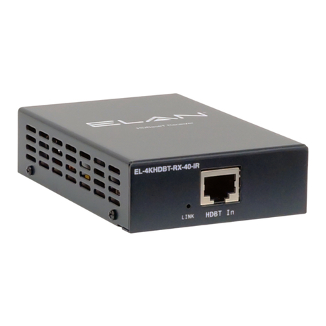
Elan EL-4KHDBT-RX-40-IR User manual

Elan
Elan EL-4KHDBT-RX-40-IRS User manual

Elan
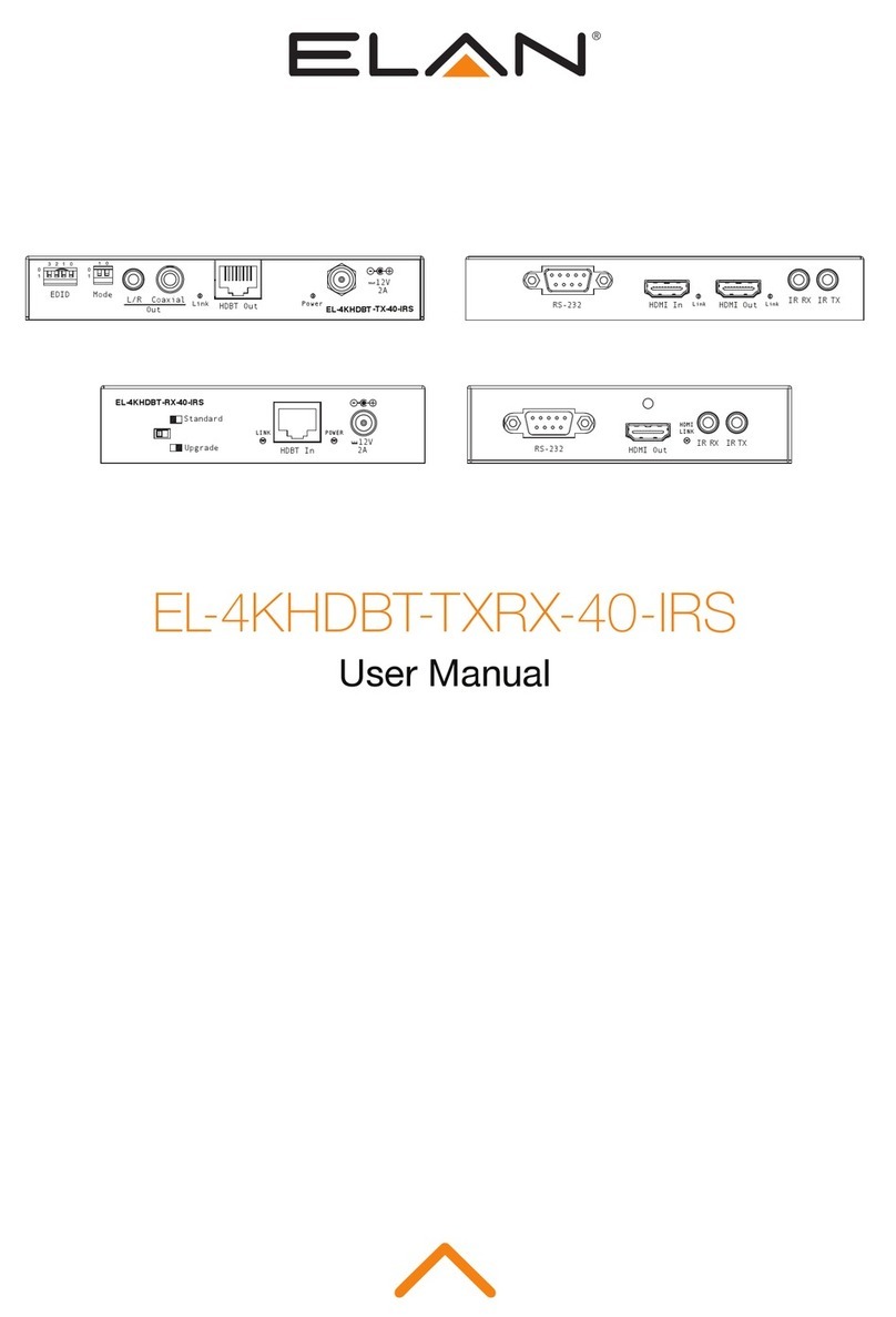
Elan EL-4KHDBT-TXRX-40-IRS User manual

Elan
Elan XM-R3 User manual

Elan
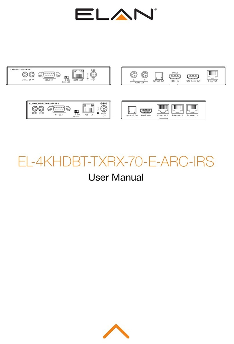
Elan EL-4KHDBT-TXRX-70-E-ARC-IRS User manual

Elan
Elan EL-4KHDBT-RX-40-18G User manual

Elan
Elan ELAN EL-4KHDBT-RX-70-E-ARC-IRS User manual

Elan
Elan EL-4KHDBT-RX-70-ARC-18G User manual