10/2010 - Art. Nr. 4200 1032 1300A 13
Commissioning
Working cycle test
Firing
Safety unit settings and checks
e
- Pre-ventilation,
- Return to ignition position,
- Ignition of electrodes,
- Valves open,
- Burner stops due to lack of gas
pressure or control unit locks because
flame is extinguished.
- If unsure, redo the above test.
The unit can only be fired once this very
important operating sequence check
has been performed.
Firing
Warning:
The burner may be only fired when
all the requirements listed in
previous sections have been met.
• Connect a microammeter (scale 0 -
100 µA DC).
• Open the quarter-turn hand-operated
fuel valve.
• Close the thermostatic circuit.
The leak tester is charged. After running
the test (30 s), the control unit
programme will relaunch. After pre-
ventilation, the burner comes on and
operates at minimum power.
• Check the following:
- the combustion
- the overall leak tightness of the gas
train using foam designed for this
purpose.
No leaks should be detected.
• Measure the gas flow shown on the
counter.
• Slowly increase the power to nominal
output, controlling the combustion
throughout. If necessary, adjust the
combustion by adjusting the
Pair:Pgas pressure ratio ( ,
Screw R).
• Adjust the servomotor control cam I
(Nominal output) to limit the maximum
opening of the air flap to the position
reached for nominal output.
• Slowly reduce the power to the
nominal output required, checking the
combustion values throughout; if
necessary, at minimum power, adjust
the combustion via parallel shifting of
the characteristic ( , Screw D).
• Adjust servomotor control cam III
(Minimum output) to limit the minimum
opening of the air flap possible during
operation to the position reached for
minimum output.
•Precautions: On principle, the
nominal output must only be modified
by adjusting the Pair:Pgas pressure
ratio ( , Screw R), and the
minimum output must only be
modified by offsetting in parallel to the
characteristic e ( , Screw D).
• After any modification to the minimum
output settings, check the combustion
at nominal output and adjust if
necessary.
• After any modification to the nominal
output settings, check the combustion
at minimum output and adjust if
necessary.
• To complete the adjustment process,
restart the burner and check the
power and the combustion. If
necessary carry out adjustments as
described above.
• Check the leaktightness of the gas
train.
• No leakage should be detected.
• Check the safety devices.
• Setting and checking the safety
devices
Gas pressure switch
• Set it to the minimum distribution
pressure.
• The burner operates at minimum
output.
• Slowly close the 90° manual shut-off
valve.
• The burner must stop due to a lack of
gas pressure.
• Open the 90° manual shut-off valve.
• The burner restarts automatically.
• The pressure switch is set.
• Fix and screw on the cover.
Air pressure switch
• See the paragraph entitled
"Determining the differential pre-
ventilation pressure and setting the
differential pressure switch" (page
16).
Leak testing device VPS:
• Open pa on the device.
• Restart the burner. After 30s the tester
should enter safety mode (red light
on).
• Reclose pa.
• o Unlock the tester safety catch by
pressing the red indicator.
The test cycle is relaunched.
The burner will be working.
• Check the leaktightness.
• Disconnect the measurement devices.
• Re-close the pressure tap.
• Reset the unit.
The burner will be working.
• Check:
- the seal between the flange and the
boiler front,
- the opening of the control circuit
(limiter and safety),
- the current on the motor relay.
• Check the combustion under actual
working conditions (doors closed,
cover in place, etc.) and check all
circuits for possible leaks.
• Establish a measurement protocol.
• Start-up automatic operation.
• Provide all the data required for proper
operation. (Inform the boiler room
operator).
• Place the boiler plate in a visible
location.
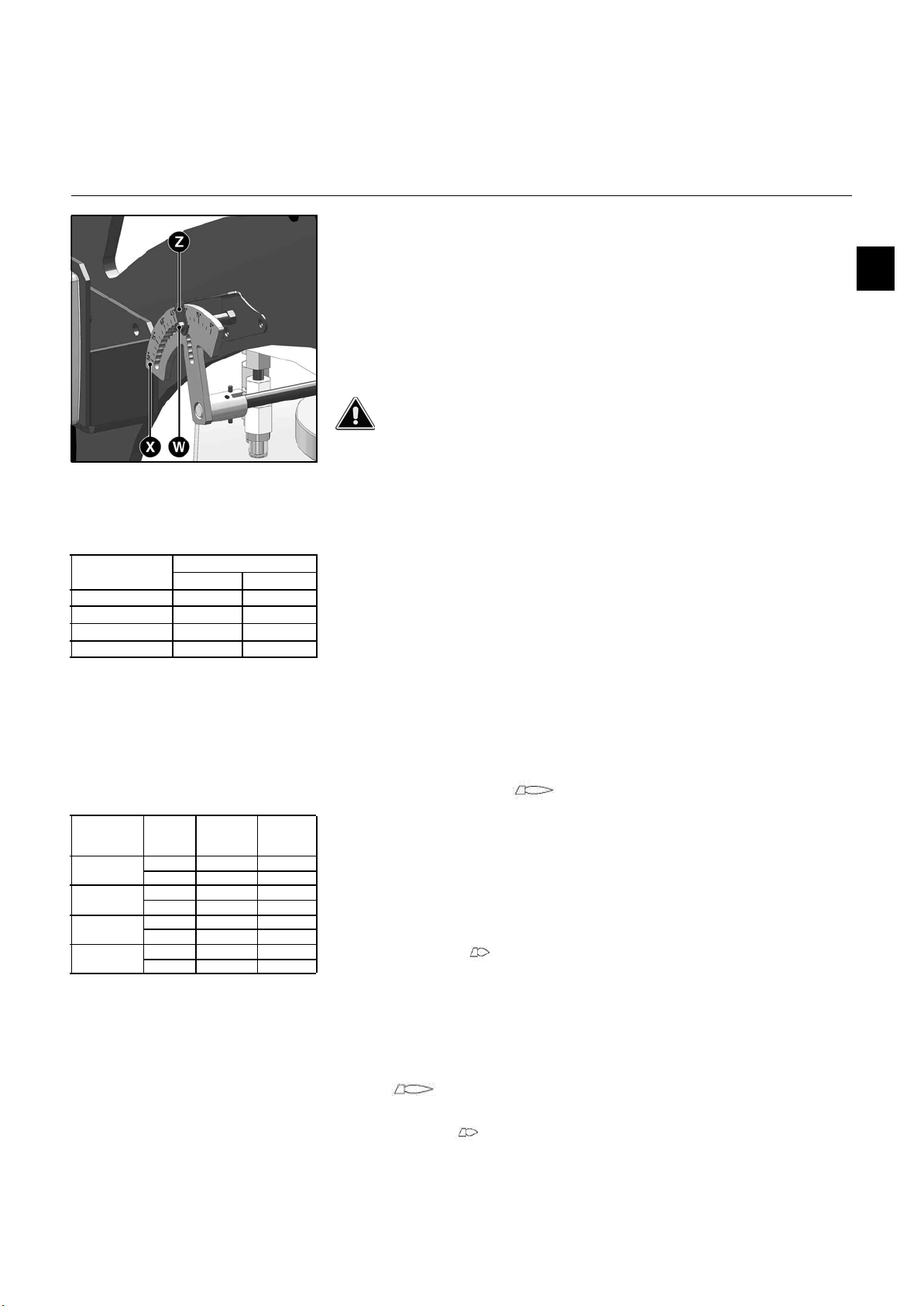
Important!
Before firing, to ensure the gas train
operates correctly, the position of the
gas flap must be checked. The table
below shows the recommended setting
depending on the burner.
• If a correction is necessary, proceed
as follows:
• Loosen screw S.
• Manually move lever Hto the
recommended position (setting
according to the table above).
• Lock into position using screw S on the
housing mounting bracket.
Pre-setting the SKP 75 according to
the table below: (these values are
given as a guide only)
Pre-setting the pressure switches on
the burner and the gas train
See the "Commissioning, Gas pressure
switch/air pressure switch" section.
Checking the operating sequence
• Open the quarter-turn hand-operated
fuel valve, then immediately close it
again.
• Switch the burner on.
• Select manual operation mode on the
control cabinet.
• Close the thermostatic circuit.
The VPS 504 S02 leak tightness test
device is switched on. After 30 s if the
test is validated, the amber light will
come on. The control unit is now
powered on.
The program should function in the
following way:
- Air flap opens to the servomotor
nominal output position,
Burner Setting (°)
50 mbar 300 mbar
N6.2400 G-V 90 45
N6.2900 G-V 90 45
N7.3600 G-V 45 45
N7.4500 G-V 45 45
Burner Gas
pressure
[mbar]
Shift from
origin
(screw D)
Pressure
ratio
(screw R)
N6.2400 G-V 50 0,5...0,9 0,8
300 2,9...4,0 2,2...2,3
N6.2900 G-V 50 0,9 1,3...1,4
300 2,9...3,7 2,2...2,3
N7.3600 G-V 50
300
N7.4500 G-V 50
300


