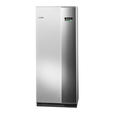
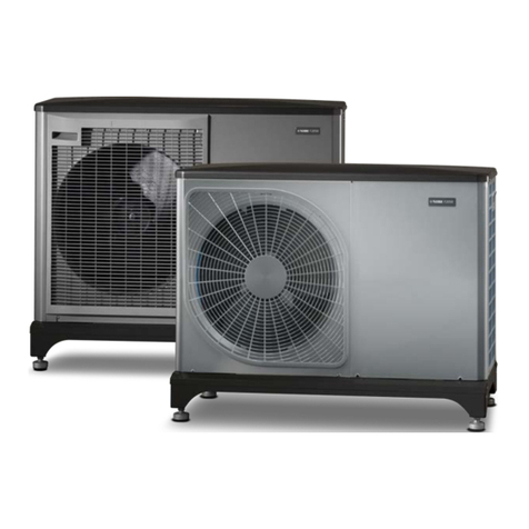
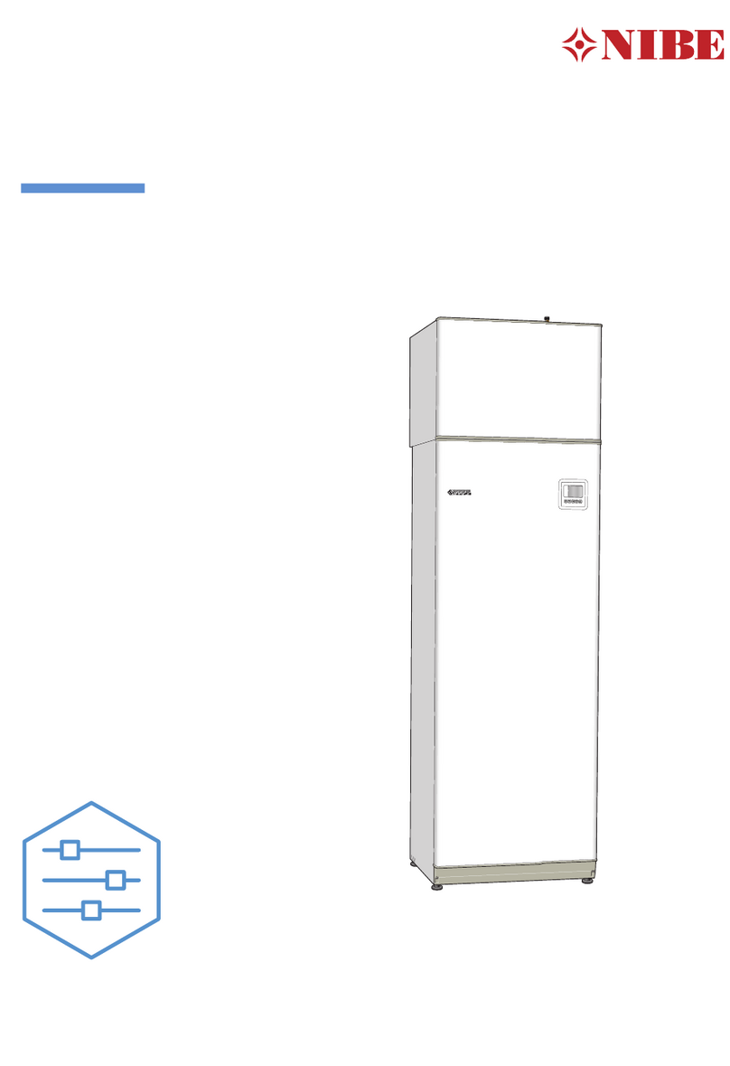
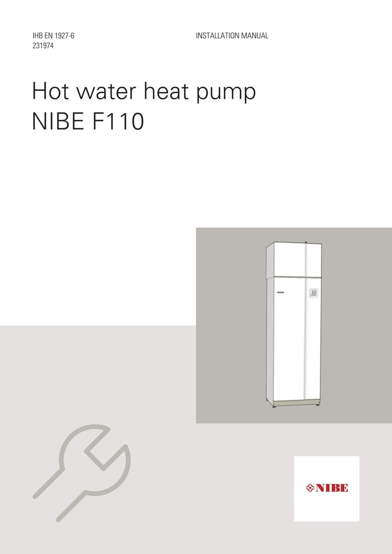
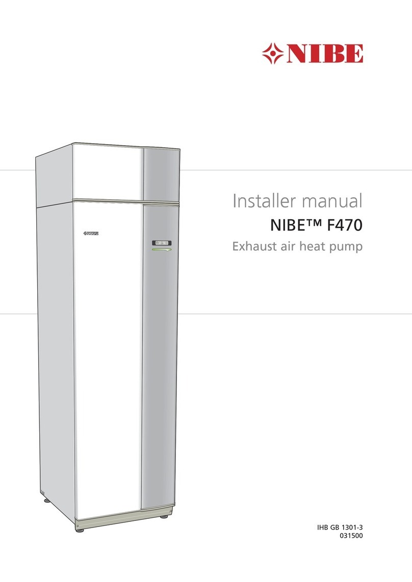
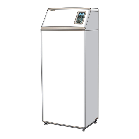
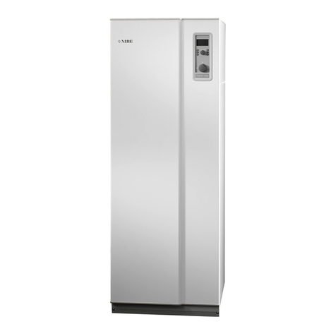
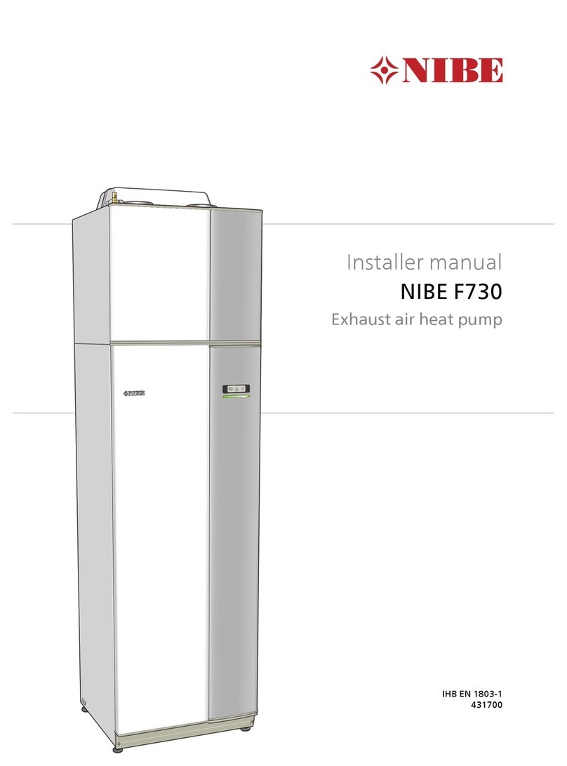
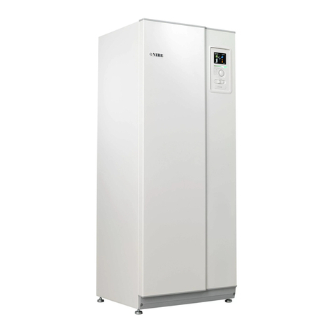
Nibe F730 User manual

User manual
LEK
NIBE F730
Exhaust air heat pump
UHB EN 1803-2
431748

Quick guide
Navigation
Ok button (confirm/select)
Back button (back/undo/exit)
Control knob (move/increase/reduce)
A detailed explanation of the button functions can be found on page
11.
How to scroll through menus and make different settings is described
on page 16.
Set the indoor climate
2X
INDOOR CLIMATE
HEAT PUMP INFO
HOT WATER
The mode for setting the indoor temperature is accessed by pressing
the OK button twice, when in the start mode in the main menu. Read
more about the settings on page 30.
Increase hot water volume
2X
1X
To temporarily increase the amount of hot water, first turn the control
knob to mark menu 2 (water droplet) and then press the OK button
twice. Read more about the settings on page 47.
In event of disturbances in comfort
If a disturbance in comfort of any type occurs there are some measures
that can be taken before you need to contact your installer. See page
72 for instructions.

Table of Contents
41 Important information
4Installation data
5Safety information
6Serial number
7F730 – An excellent choice
82 The heat pump – the heart of the house
9Heat pump function
11Contact with F730
21Maintenance of F730
303 F730 – at your service
30Set the indoor climate
47Set the hot water capacity
52Get information
56Adjust the heat pump
714 Disturbances in comfort
71Info-menu
71Manage alarm
72Troubleshooting
755 Technical data
766 Glossary
80Item register
83Contact information
3NIBE F730Table of Contents |

1 Important information
Installation data
F730Product
Serial number
Installation date
Installer
Accessories
✔
Extra shunt ECS
40/41
Room unit RMU 40
Communications
module SMS 40
SetFact.
sett.
NameNo.
0temperature(curve offset)1.1
9heating curve (curve
slope)
1.9.1
20min. flow line temp.1.9.3
75%fan sp. exhaust air (nor-
mal)
5.1.5
MaxInstalled electrical output
Serial number must always be given
Certification that the installation is carried out according to instructions
in the accompanying installer manual and applicable regulations.
_________________________Signed__________________Date
NIBE F730Chapter 1 | Important information4

Safety information
This appliance can be used by children aged from 8
years and above and persons with reduced physical,
sensory or mental capabilities or lack of experience
and knowledge if they have been given supervision or
instruction concerning use of the appliance in a safe
way and understand the hazards involved. Children
shall not play with the appliance. Cleaning and user
maintenance shall not be made by children without
supervision.
Rights to make any design or technical modifications
are reserved.
©NIBE 2017.
NOTE
F730 must be installed via an isolator switch with a
minimum breaking gap of 3 mm.
NOTE
If the supply cable is damaged, only NIBE, its service
representative or similar authorised person may replace
it to prevent any danger and damage.
NOTE
Do not start the heat pump, if there is a risk that the
water in the system has frozen.
5NIBE F730Chapter 1 | Important information

Symbols
NOTE
This symbol indicates danger to person or machine .
Caution
This symbol indicates important information about what you should
observe when maintaining your installation.
TIP
This symbol indicates tips on how to facilitate using the product.
Serial number
The serial number can be found at the bottom right of the front cover and
in the info menu (menu 3.1).
Serial number
Caution
You need the product's (14 digit) serial number for servicing and support.
NIBE F730Chapter 1 | Important information6

F730 – An excellent choice
F730 is part of a new generation of heat pumps, which have been intro-
duced to supply your home with inexpensive and environmentally friendly
heating. Heat production is safeand economical with integrated hot water
heater, immersion heater, circulation pump and control system.
The heat pump can be connected to an optional low temperature heat
distribution system. e.g. radiators, convectors or underfloor heating. It is
also prepared for connection to several different accessories, for example
climate systems with different temperatures.
F730 is equipped with acontrol computer for good comfort, good economy
and safe operation. Clear information about status, operation time and
all temperatures in the heat pump are shown on the large and easy to
read display. This means, for example, that external unit thermometers
are not necessary.
Excellent properties for F730:
■Inverter controlled compressor
The heat pump has an inverter controlled compressor that automatically
adapts itself optimally and economically to your house and supplies your
installation with renewable energy.
■Integrated water heater
There is a water heater integrated in the heat pump, which is insulated
with environmentally friendly cellular plastic for minimal heat loss.
■Scheduling the indoor comfort and hot water
Heating and hot water as well as ventilation, can be scheduled for each
day of the week or for longer periods (vacation).
■Display with user instructions
The heat pump has a large display with easy-to-understand menus that
facilitate setting a comfortable climate.
■Simple troubleshooting
In the event of a fault, the heat pump display shows what happened
and the actions to be taken.
7NIBE F730Chapter 1 | Important information

2 The heat pump – the heart of
the house
A
DF
B
C
E
H
G
80 °C
22 °C 0 °C
5 °C 0 °C
55 °C 45 °C
Värmebärare
Köldmedium
Rumsluft
Heating medium
Ventilation air
Refrigerant
Evaporator
Condenser
Compressor
1
2
3
Expansion valve
NIBE F730Chapter 2 | The heat pump – the heart of the house8

Heat pump function
An exhaust air heat pump makes use of the heat in the building's ventila-
tion air to heat up the accommodation. The conversion of the ventilation
air's energy to accommodation heating is done in three different circuits.
From the outgoing ventilation air (1), free heating energy is retrieved from
the accommodation and transported to the heat pump. The heat pump
increases the retrieved heat's low temperature to a high temperature in
the refrigerant circuit, (2). The heat is distributed around the building in
the heating medium circuit (3).
Ventilation air
The hot air is transferred from the rooms to the heat pump via the house
ventilation system.
A
The fan then routes the air to the heat pump’s evaporator. Here, the air
releases the heating energy and the air's temperature drops significantly.
The cold air is then blown out of the house.
B
Refrigerant circuit
A liquid, a refrigerant, circulates in a closed system in the heat pump which
also passes the evaporator. The refrigerant has a very low boiling point. In
the evaporator the refrigerant receives the heat energy from the ventilation
air and starts to boil.
C
The gas that is produced during boiling is routed into an electrically
powered compressor. When the gas is compressed, the pressure increases
and the gas's temperature increases considerably, from -5°C to approx.
100 °C.
D
From the compressor, the gas is forced into a heat exchanger, condenser,
where it releases heat energy to the heat pump’s heating section,
whereupon the gas is cooled and condenses to liquid form again.
E
As the pressure is still high, the refrigerant can pass an expansion valve,
where the pressure drops so that the refrigerant returns to its original
temperature. The refrigerant has now completed a full cycle. It is routed
to the evaporator again and the process is repeated.
F
Heat medium circuit
The heat energy that the refrigerant produces in the condenser is retrieved
by the climate system's water, heating medium, which is heated to 55 °C
(supply temperature).
G
The heating medium circulates in aclosed system and transports the heated
water's heat energy to the heat pump's integrated hot water heater and
the radiators/heating coils of the house.
H
The temperatures are only examples and may vary between different installations and
time of year.
9NIBE F730Chapter 2 | The heat pump – the heart of the house

The heat pump’s integrated water heater is in the heating section. The
heating medium heats the hot water.
I
The temperatures are only examples and may vary between different installations and
time of year.
NIBE F730Chapter 2 | The heat pump – the heart of the house10

Contact with F730
Display unit
A
B
C
D
E
F
Display
Status lamp
OK button
Back button
Control knob
Switch
INDOOR CLIMATE
HEAT PUMP INFO
HOT WATER
F730 GUSB port
There is a display unit on the front of the heat pump, which is used to
communicate with F730.. Here you:
■switch on, switch off or set the heat pump in emergency mode.
■sets the indoor climate and hot water as well as adjusts the heat pump
to your needs.
■receive information about settings, status and events.
■see different types of alarms and receive instructions about how they
are to be rectified.
Display
Instructions, settings and operational information areshown on the
display. You can easily navigate between the different menus and
options to set the comfort or obtain the information you require.
A
11NIBE F730Chapter 2 | The heat pump – the heart of the house

Status lamp
The status lamp indicates the status of the heat pump. It:
■lights green during normal operation.
■lights yellow in emergency mode.
■lights red in the event of a deployed alarm.
B
OK button
The OK button is used to:
■confirm selections of sub menus/options/set values/page in the
start guide.
C
Back button
The back button is used to:
■go back to the previous menu.
■change a setting that has not been confirmed.
D
Control knob
The control knob can be turned to the right or left. You can:
■scroll in menus and between options.
■increase and decrease the values.
■change page in multiple page instructions (for example help text
and service info).
E
Switch
The switch assumes three positions:
■On ()
■Standby ( )
■Emergency mode ( )
Emergency mode must only be used in the event of a fault on the
heat pump. In this mode, the compressor switches off and the im-
mersion heater engages. The heat pump display is not illuminated
and the status lamp illuminates yellow.
F
NIBE F730Chapter 2 | The heat pump – the heart of the house12

USB port
The USB port is hidden beneath the plastic badge with the product
name on it.
The USB port is used to update the software.
Visit http://www.nibeuplink.com and click the "Software" tab to
download the latest software for your installation.
G
13NIBE F730Chapter 2 | The heat pump – the heart of the house

Menu system
INDOOR CLIMATE
HEAT PUMP INFO
HOT WATER
SERVICE
Indoor temperature - (if room sensors are installed)
Hot water temp.
Temporary lux (if activated)
Outdoor
temperature
Estimated amount of hot water
Information about
operation
INDOOR CLIMATE
Setting and scheduling the indoor climate. See page 30.
Menu 1
HOT WATER
Setting and scheduling hot water production. See page 47.
Menu 2
INFO
Display of temperature and other operating information and access to
the alarm log. See page 52.
Menu 3
HEAT PUMP
Setting time, date, language, display, operating mode etc. See page 56.
Menu 4
NIBE F730Chapter 2 | The heat pump – the heart of the house14

Symbols in the display
The following symbols can appear in the display during operation.
DescriptionSymbol
This symbol appears by the information sign if thereis inform-
ation in menu 3.1 that you should note.
These two symbols indicate whether the compressor or addi-
tion is blocked in F730.
These can, for example, be blocked depending on which op-
erating mode is selected in menu 4.2, if blocking is scheduled
in menu 4.9.5 or if an alarm has occurred that blocks one of
them.
Blocking the compressor.
Blocking additional heat.
This symbol appears if periodic increase or lux mode for the
hot water is activated.
This symbol indicates whether "holiday setting" is active in
4.7.
This symbol indicates whether F730 has contact with Uplink.
This symbol indicates the actual speed of the fan if the speed
has changed from the normal setting.
This symbol indicates whether solar heating is active.
Accessory needed.
15NIBE F730Chapter 2 | The heat pump – the heart of the house

INDOOR CLIMATE
HEAT PUMP INFO
HOT WATER
temperature
INDOOR CLIMATE 1
ventilation
scheduling
advanced
off
normal
Marked main menu
Menu number – marked sub menu Name and menu number – main menu
Symbol – main
menu
Status information – sub menus
Name – sub menusSymbols – sub menus
Operation
To move the cursor, turn the control knob to the left or the
right. The marked position is white and/or has a turned up tab.
Selecting menu
To advance in the menu system select a main menu by marking
it and then pressing the OK button. A new window then opens with sub
menus.
Select one of the sub menus by marking it and then pressing the OK button.
NIBE F730Chapter 2 | The heat pump – the heart of the house16

Selecting options
economy
comfort mode2.2
normal
luxury
Alternative
In an options menu the current selected option is indicated by a green
tick.
To select another option:
1. Mark the applicable option. One of the options is pre-selected
(white).
2. Press the OK button to confirm the selected option. The selected
option has a green tick.
17NIBE F730Chapter 2 | The heat pump – the heart of the house

Setting a value
time & date4.4
time
day
year
month
24 h
12 h
date
Values to be changed
To set a value:
1. Mark the value you want to set using the control knob.
2. Press the OK button. The background of the value becomes
green, which means that you have accessed the setting mode.
3. Turn the control knob to the right to increase the value and to
the left to reduce the value.
4. Press the OK button to confirm the value you have set. To change
and return to the original value, press the Back button.
NIBE F730Chapter 2 | The heat pump – the heart of the house18

Use the virtual keyboard
Different keyboards
In some menus where text may require entering, a virtual keyboard is
available.
Depending on the menu, you can gain access to different character sets
which you can select using the control knob. To change character table,
press the Back button. If a menu only has one character set the keyboard
is displayed directly.
When you have finished writing, mark "OK" and press the OK button.
19NIBE F730Chapter 2 | The heat pump – the heart of the house

Scroll through the windows
A menu can consist of several windows. Turn the control knob to scroll
between the windows.
Current menu
window
Number of windows
in the menu
Scroll through the windows in the start guide
language4.6
Arrows to scroll through window in start guide
1. Turn the control knob until one of the arrows in the top left corner (at
the page number) has been marked.
2. Press the OK button to skip between the steps in the start guide.
Help menu
In many menus there is a symbol that indicates that extra help is
available.
To access the help text:
1. Use the control knob to select the help symbol.
2. Press the OK button.
The help text often consists of several windows that you can scrollbetween
using the control knob.
NIBE F730Chapter 2 | The heat pump – the heart of the house20
Other manuals for F730
5
Table of contents
Other Nibe Heat Pump manuals
Popular Heat Pump manuals by other brands

McQuay
McQuay MHC Standard Range Installation & maintenance data

DeDietrich
DeDietrich AWHP-V220 user guide

Black & Decker
Black & Decker BDXBT53 instruction manual

Carrier
Carrier bryant 607E K Series installation instructions

MrCool
MrCool DIY Series user manual

Viessmann
Viessmann Vitocal 350-G Installation and service instructions

WarmPool
WarmPool WP90 Installation and user guide

Trane
Trane WSHP-DS-6 user manual

Nordyne
Nordyne Q5RF-X24KA installation instructions

ClimateMaster
ClimateMaster Genesis Standard (GR) Series Installation, operation & maintenance instructions

COSMOGAS
COSMOGAS ECOTOWER 6 INSTALLATION, USE AND MAINTENANCE MANUA

FRIGOMAR
FRIGOMAR CU50VFD User instruction