Electro-Automatik BC 800 R Series User manual

BC 812-20R : 27 150 311
BC 824-10R : 27 150 312
BC 848-05R : 27 150 313
BC 824-20R : 27 150 314
BC 848-10R : 27 150 315
BC 812-40R : 27 150 316
操作说明书
Instruction Manual
BC 800 R
Battery Charger
320W / 640W


3
BC 800 R 系列
产品说明书
CN
日期:16.04.2018
危险电压
警告:本产品输出电压可能上升至危险级别(> 60 VDC)
!
产品上所有带电元件必须有外遮盖。输出端的所有操
作必须在产品与主电源(电源开关关闭)断开时才能
执行,且可只有受训过电流危险知识的专业人员执行
此类操作。负载与本产品间的任何连接必须有防碰擦
装置。连到功率输出端的应用设备必须配置好,并且
有保险丝熔断保护,这样可防止使用过程中由于过载
或误操作损坏产品或更严重事情发生。
安全说明
• 本电池充电器仅能充符合产品规格的电池或电池组
(并联或串联)。如果未激活限制,最大充电电流
等同于额定电流!
• 不要连接不可充电电池!
• 连接电池前请先关闭产品!
• 电池连接线的直径必须符合产品的额定输出电流。
• 请避免损坏产品,勿将金属元件插入通风槽,不要
阻挡通风槽!
• 必须由专业受训人员执行市电连接。
• 只能选用合适的连线,按照通用安全措施连到市
电。
• 避免直接接触太阳光和湿气。
• 电池给电池充电时,可能会从电池内产生大量可燃
气体。必须随时保证空气流通良好,禁止在电池周
围有明火和火花出现。
关于
Elektro-Automatik GmbH & Co. KG
Helmholtzstrasse 31-37
41747 Viersen
Germany
电话: 02162 / 37850
传真: 02162 / 16230
网址: www.elektroautomatik.cn
© Elektro-Automatik
严禁再版、复印或部分错误地使用该说明书,否则将承
担该行为导致的法律后果。

4
© 2006, Elektro-Automatik GmbH & Co. KG
Irrtümer und Änderungen vorbehalten
CN
BC 800 R 系列
产品说明书
日期:16.04.2018
目录
页码
1.一般信息.................................................................................... 5
1.1 简介..................................................................................... 5
1.2 目检..................................................................................... 5
1.3 供应清单................................................................................. 5
2.安装........................................................................................ 5
2.1 安装..................................................................................... 5
2.2 与市电的连接............................................................................. 5
2.3 感测端的连接............................................................................. 5
2.4 直流输出端的连接......................................................................... 5
2.5 模拟接口的连接........................................................................... 5
3.功能描述.................................................................................... 6
3.1 电池类型................................................................................. 6
3.2 充电程序................................................................................. 6
3.2.1 充电特性............................................................................ 6
3.3 电池监控................................................................................. 6
3.4 温度感测................................................................................. 6
3.5 远程感测(Remote sense)................................................................ 7
3.6 电源模式(Power Supply Mode)........................................................... 7
3.7 过压保护(OVP)........................................................................ 7
3.8 过温保护(OT).......................................................................... 7
3.9 错误..................................................................................... 7
3.10远程控制................................................................................. 7
3.11自动充电模式............................................................................. 7
4.技术参数.................................................................................... 8
4.1 产品尺寸图............................................................................... 9
5.操作....................................................................................... 11
5.1 给产品供电.............................................................................. 11
5.2 连接电池................................................................................ 11
5.3 选择电池充电曲线........................................................................ 11
5.4 开始充电................................................................................ 11
5.5 停止充电................................................................................ 11
5.6 用小电流充电............................................................................ 11
5.7 并联待机操作............................................................................ 11
5.8 电源模式(
Power Supply Mode
)............................................................ 11
5.9 模拟接口................................................................................ 12
5.9.1 连接................................................................................ 12
5.9.2 接口引脚分布....................................................................... 12
5.9.3 应用举例........................................................................... 12
5.10激活自动充电模式........................................................................ 13
6.其它....................................................................................... 13
6.1 重设控制面板............................................................................ 13

5
BC 800 R 系列
产品说明书
CN
日期:16.04.2018
关于产品
1. 一般信息
1.1 简介
BC 800 R系列微处理器控制电池充电器专门设计成墙
挂式结构,以空气对流为冷却方式。
本产品专门给不同铅性电池充电。第三阶段,温度补偿
充电程序可快速、完整、仔细地给电池充电。
而且,产品还有一电源模式,其输出电压变得可调。
电源输出端有反接保护,短路保护和过载保护。为了
保护负载,产品还有过压保护(OVP)功能。出现过
温(OT)时,电源输出关闭,直至温度冷却,又自动
打开。
1.2 目检
收到本产品后,请检查是否有外观受损痕迹。如有,请
不要操作本产品,应立即联系您的供应商。
1.3 更换内部保险丝
提示:这不适用于
BC 812-40 R
产品,因为该产品的保
险丝位于前面保险丝座上。
电源保险丝位于产品里面。打开产品前,先将它完全
与市电断开。
必须是接受过危险知识和安全规则训练的技术人员才可
在打开的产品上操作。
要替换保险丝,需先松开前盖螺丝,小心地取下盖。保
险丝就在主板上,位于左手边。
1.4 供应清单
1 x 电池充电器
1 x 印刷版使用说明书
1 x 电源插座(仅针对外壳类别1)
1 x 温度传感器LM335Z (10mV/K)
1 x 组装套件(仅针对BC 812-40 R产品)
2. 安装
2.1 安装
本产品设计成墙挂式结构。安装时需按空气顺着通风槽
流出的方式安装。注意产品的上方和下方应保留一定空
间(至少15cm),以保证足够的冷却效果。
也可见第9页图。
2.2 与市电的连接
本系列所有型号都具有正向PFC (功率因素校正)和
宽范围输入电压。可在90V至264VAC输入电压,以及
45Hz至65Hz频率下工作。
按照前板丝印将电源线连到3位端子上(型号
为:Phoenix Combicon GMSTB 2,5/3-ST-7,62)。
仅受训技术人员方可执行。必须使用适当直径的电源
线,因为本产品无电源开关。电源输入端由一标准的
5x20mm保险丝保护,它装于产品内部。
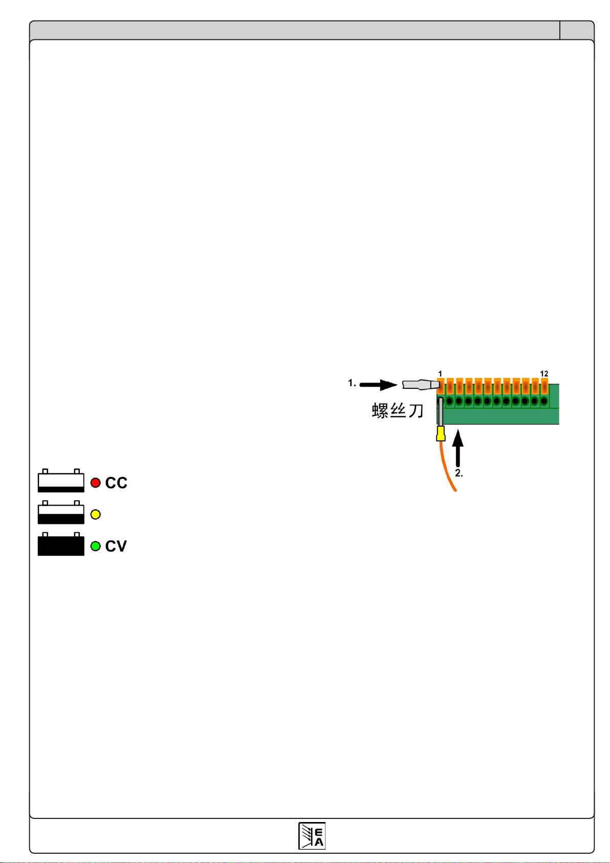
2.3 直流输出端与感测端的连接
直流输出端与远程感测输入端位于产品前面。除BC
812-40 R产品外,其它型号都采用同类型的卡紧型端
子,适合安装直径为0.08mm² (28 AWG)至4mm² (12
AWG)的连线。如果可以,线尾请装上线套。
连线夹紧步骤:
而BC 812-40 R产品,则经由螺丝端子连到电池上。
2.4 模拟接口的连接
见章节„5.9 模拟接口“。
6
© 2006, Elektro-Automatik GmbH & Co. KG
Irrtümer und Änderungen vorbehalten
CN
BC 800 R 系列
产品说明书
日期:16.04.2018
3. 功能描述
3.1 电池类型
本电池充电器可用来充不同类型的铅性电池,如铅
酸,GEL或AGM类型。任何类型的充电都按照三个阶
段,以及温度补偿(仅当连接了温度传感器时)充电
程序进行。按下前板按钮可选择电池类型。相关的充
电曲线图主要不同在于每节电池的电压(见右表)。
3.2 充电程序
注意!不良电池(
UBatAct = <0.4 x UBatNom
)不能充电!
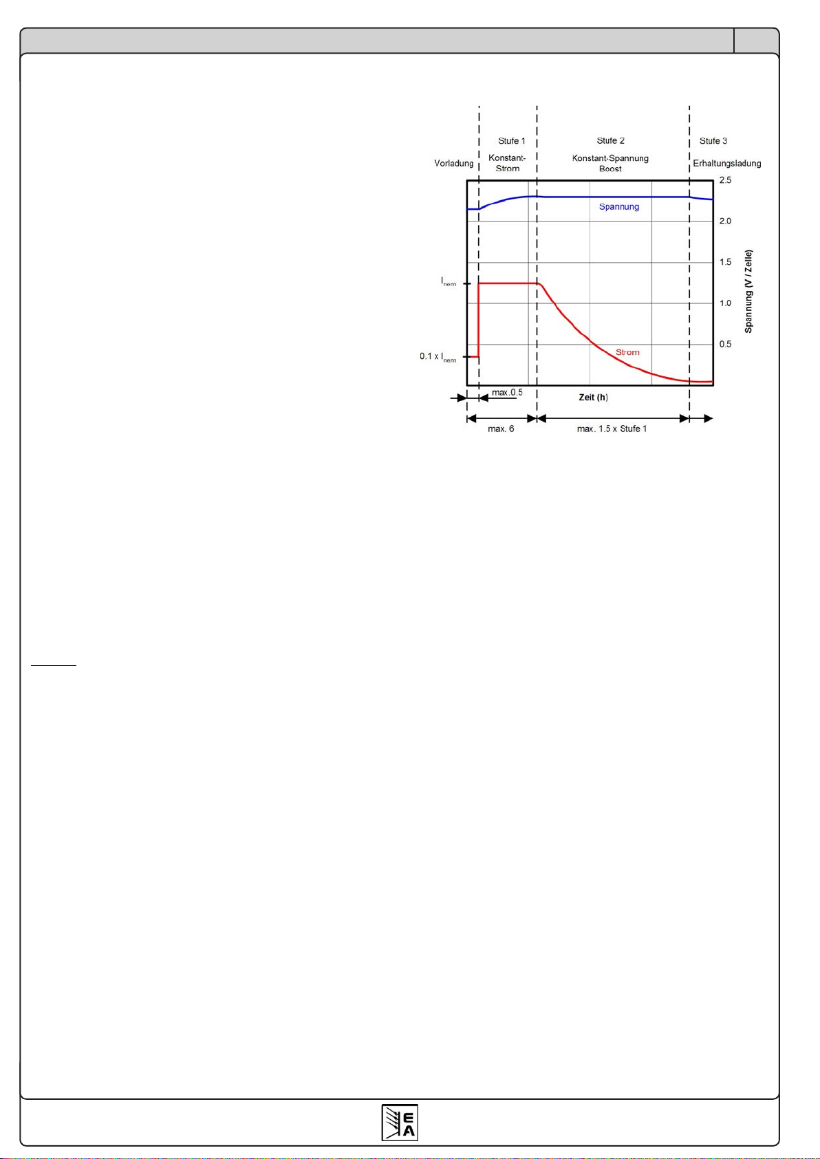
充电程序按照I-U-U特性进行。
充电程序的第一步为预充,并以较小的输出电流(0.1
x INom)充电。预充对过放的电池非常有效,以UBatAct =
>0.2 x UBatNom充电,使之能修复和重复给电池充电。一
旦输出电压上升至,或者最大限度地充了30分钟后,充
电程序将转为普通充。预充和普通充都通过交通灯型的
红色指示灯指示出来。
在普通充电阶段,电池以全电流INom充电(或30%的输
出电流I-Limit)。
恒流充完成后,或进行了最长6个小时的充电后,充电
程序转为快充(黄色灯亮)。
快充时电压减少,一旦充电电流为INom的5%,或快充
时间超过普通充的1.5倍,充电将进入涓充。
如果充电电流在INom的5%以下,通过绿色状态灯,指
示电池已充满。
涓充时,以涓充电压无限期地给电池充电,直至出错
或断电而停止或中断。
建议在快充和涓充阶段使用温度补偿,可防止电池产
生气体。
提示:可激活30% I-Limit,手动减少输出电流。激活
该功能,需按住“Charging Proles”按钮长达3s。
I-Limit对以小电流给小电池充电时非常有用。
3.2.1充电特性
3.3 电池监控
单个电池或一组电池都可接到产品前板标有“Battery”
的特定端子上。本产品能对输出端的反极性和错误电池
电压进行监控。若电池极性反接到充电器上,或者电池
电压太低或太高,都不会启动充电程序。
注意!仅能连接与产品额定充电电压相符的电池。否则
可能会损坏电池和/或产品.
3.4 温度感测
我们建议给电池充电时,启动温度补偿功能,以免产
品产生危险气体。
未连接温度传感器时,则以对应25°C环境温度的恒定
电压给电池充电。连接温度传感器时,将它直接接到
模拟接口的第1和6脚,然后放在电池周围或直接附在电
池上。充电开始时即开始检测和使用。如果测量到的温
度低于高于+50°C,则停止充电。待温度下降至<+45°C
后,继续自动充电。该功能仅在安装有温度传感器时才
工作。只要电池过温错误出现,错误灯就一直闪烁。
如果温度低于-15°C,则停止温度补偿。如果在充电过
程中取下或损坏传感器,产品则按照25°C的充电电压
继续充电。
为了让用户发现温度相关的错误,即使该温度值已回到
正常范围,LED灯也一直闪烁。再次开始充电或转为电
源模式会清除错误,如果温度正常,LED不再闪烁。
可使用LM335或类似温度传感器,充电电压的温度补偿
为每节电池4mV/°C。
功能描述

7
BC 800 R 系列
产品说明书
CN
日期:16.04.2018
功能描述
3.5 远程感测(Remote sense)
要补偿负载线上的压降,产品前板还具有一远程感测输
入端。按正确极性连线到此,感测电池的电压。远程感
测端可补偿多达2V的电压。
不用该感测输入端时,就让它空闲着,不用连跳线到
输出端。
感测线的直径非关键条件。
3.6 电源模式(Power Supply Mode)
如果用“充电配置文档”按钮选择了“Power Supply
Mode”,本产品就可当电源用。在该模式下,用电位
器可在限定范围内(见„4. 技术参数“)调节输出电
压。它可以按恒压或恒流模式操作(U-I特性),并通
过前板的绿色或红色LED灯指示出来。。
该模式适合并联待机操作,也见„5.7 并联待机操作“。
3.7 过压保护(OVP)
本系列所有型号都有过压保护电路。如遇过压错误,
不论是因内部故障或外部原因引起的,电源输出关
闭,且以“Error”LED灯闪烁和模拟接口的9脚指示
出该错误。OV过压错误消失后,输出再次打开,并开
始充电。
3.8 过温保护(OT)
本系列所有型号还有内温监控功能。如遇过热,电源输
出暂时关闭,直至冷却后又自动打开。
充电仅被打断,并未停止。以闪烁的“Error”LED灯
和模拟接口的9脚指示出来该状态。
3.9 错误
任何错误都由闪烁的“Error”LED灯指示出来。下面
为LED灯提示的基本错误:
• 过压 (OVP)
• 过温 (OT)
• 连接到电压源的电池或其他负载的极性连接错误
OVP和OT错误也在模拟接口上指示出来。
在电池充电器模式,即,非电源模式,将提示下列额
外的错误信号:
• 连接电池的电压太低或太高
• 温度传感器失效(连线断或其它)
3.10远程控制
本系列所有型号的前板上都配有一12脚模拟端口。可
通过它监控产品状态,以及远程启动/停止充电程序。
也可见章节5.9以及之后的描述。
3.11自动充电模式
可以激活这个额外的操作模式,一旦产品接上市电或接
上电池后,自动给电池充电。详情请看„5.10 激活自动
充电模式“。

8
© 2006, Elektro-Automatik GmbH & Co. KG
Irrtümer und Änderungen vorbehalten
CN
BC 800 R 系列
产品说明书
日期:16.04.2018
4. 技术参数
操作产品
BC 812-20R BC 824-10R BC 848-05R BC 812-40R BC 824-20R BC 848-10R
电源输入
输入电压 90…264V 90…264V 90…264V 90…264V 90…264V 90…264V
输入频率 45…65Hz 45…65Hz 45…65Hz 45…65Hz 45…65Hz 45…65Hz
功率因数值 >0.99 >0.99 >0.99 >0.99 >0.99 >0.99
230V时输入电流 1.6A 1.6A 1.6A 3.4A 3.2A 3.2A
输入保险丝 M6.3A M6.3A M6.3A T10A T10A T10A
输出 - 电压
电池电压UBat 12V 24V 48V 12V 24V 48V
可调范围 10…15V 20…30V 40…60V 10…15V 20…30V 40…60V
带载10…90%时的稳定度 <0.05% <0.05% <0.05% <0.05% <0.05% <0.05%
市电波动范围在±10% ∆UIN时的稳定度 <0.02% <0.02% <0.02% <0.02% <0.02% <0.02%
纹波 <40mVPP <100mVPP <150mVPP <10mVPP <100mVPP <150mVPP
带载10-100%的调整 <2ms <2ms <2ms <2ms <2ms <2ms
输出 - 电流
额定电流 20A 10A 5A 40A 20A 10A
带载0…100% ∆UOUT时的稳定度 <0.15% <0.15% <0.15% <0.15% <0.15% <0.15%
市电波动范围在±10% ∆UIN时的稳定度 <0.05% <0.05% <0.05% <0.05% <0.05% <0.05%
纹波 <60mAPP <35mAPP <12mAPP <19mAPP <65mAPP <25mAPP
输出 - 功率
额定功率 300W 300W 300W 600W 600W 600W
其它
工作温度 0…50°C 0…50°C 0…50°C 0…50°C 0…50°C 0…50°C
储存温度 -20…70°C -20…70°C -20…70°C -20…70°C -20…70°C -20…70°C
相对湿度 <80% <80% <80% <80% <80% <80%
尺寸 (WxHxD) 218x83x163mm 218x83x163mm 218x83x163mm 90x360x240mm 218x83x163mm 218x83x163mm
重量 2.2kg 2.2kg 2.2kg 6.5kg 2.2kg 2.2kg
产品编号 27150311 27150312 27150313 27150316 27150314 27150315
安全标准
EMC标准
过压等级
保护等级
EN 60950
EN 61326, EN 550022 等级 B
等级 II
等级 I

9
BC 800 R 系列
产品说明书
CN
日期:16.04.2018
操作产品
4.1 产品尺寸图
外壳类别 1: 20A以下产品型号

10
© 2006, Elektro-Automatik GmbH & Co. KG
Irrtümer und Änderungen vorbehalten
CN
BC 800 R 系列
产品说明书
日期:16.04.2018
操作产品
外壳类别 2,为BC 812-40 R外壳
5. 操作
5.1 给产品供电
产品与市电连接后,不会形成电源开关的功能,而是
立即工作。
关闭产品后将存储最后状态(选定模式,输出条件),
以便下次启动时自动恢复。因此在遇断电等这样的中断
并恢复后,可继续工作。意思是,它会继续充电,只要
充电条件未改变(未出现电池电压或极性错误,电池温
度错误,电池未连接)。
5.2 连接电池
本电池充电器只允许给符合产品输出电压的电池充电。
如果激活“I-Limit”,充电电流为最大值或INenn的30%
。加上温度补偿电压,最大充电电压约为2.43V/节(
根据电池型号)。
电池连线的直径必须按照充电器的额定电流而选用。
注意!连接或断开电池前,必须检查是否已停止充电。
此时印在前板上的电池水平符号旁的
LED
灯都不亮。
5.3 选择电池充电曲线
充电前选择电池曲线图,需先关闭输出。用“Charging
Proles”按钮选择三个充电曲线的其中一个,所有曲
线图都是针对铅性电池。
LED
灯指示所选电池类型。
选定的充电曲线考虑了特定电池每节的电压,这是由
电池生产商指定:
普通充 快充 涓充
铅酸电池 2V/节2.38V/节2.28V/节
Gel电池 2V/节2.40V/节2.28V/节
AGM电池 2V/节2.43V/节2.28V/节
5.4 开始充电
按下“
Start / Stop Charging
”按钮,或使用模拟接口
的引脚
8
可启动充电。下面错误现象会阻止充电程序的
启动:
•
电池没连接
•
电池电压太低(
LED
闪烁)
•
电池电压太高(
LED
闪烁)
•
电池温度太高(
LED
闪烁)(仅当温度传感器连接
时)
•
电池反接
按照选定电池曲线和按照“充电程序”章节的充电特性
图形描述充电。当前激活的充电阶段以前板丝印的电池
充满水平符号对应的LED灯指示出来。
充电程序也由模拟接口上的“Charging”信号指示。
提示:手动停止充电后需要等约
30s
以上方可再次开
始充电。长时间断电或者手动关闭后也适用该规则。
短时间断电(
<5s
)造成充电程序暂停,可由产品本
身进行补偿。
11
BC 800 R 系列
产品说明书
CN
日期:16.04.2018
操作产品
5.5 停止充电
“
Start / Stop Charging
”按钮还可用来立刻停止任何
阶段的充电。然后关闭输出,LED不再亮。
连接或断开电池前,必须停止充电!
5.6 用小电流充电
小容量的电池通过激活“
I-Limit
”功能,每充电阶段都
以小电流(正常电流的
30%
)充电。
减少后的最大充电电流以“
I-limit xA
”(“
Error
”灯旁
边)注明在前板上。“
I-Limit 30%
”灯指示已激活的限
流功能长期有效(只要未出现错误)。
按住“
charging proles
”按钮长达
3
秒,可随时激活该
功能。
5.7 并联待机操作
提示:只有选择了“
Power Supply Mode
”后,才适合
进行并联待机操作。
在电源模式下(见章节5.8),本产品可进行并联待机
操作,也可跟另外一处于充电模式的充电器一起操作。
从而产生UPS的工作特性。
5.8 电源模式(
Power Supply Mode
)
本充电器可当电源用,但其输出电压可调范围被限定。
要选择电源(Power Supply Mode)模式,需在输出关
闭时,按下“
Charging Proles
”按钮。
按下“Start / Stop Charging”按钮可打开或关闭电源
输出。
输出打开时,绿色状态灯指示恒压(CV)操作,或红
色状态灯指示恒流(CC)操作。如下图:
两种运行模式根据输出端的电压/电流状态而定。
输出电流被限为产品额定电流,且不可调。
若想用电位器在指定范围内调节输出电压,需先打开
输出。
只有输出关闭时方可连接负载。负载线的直径必须符合
产品的额定电流。
提示:在电源模式下,产品也能通过闪烁的错误灯指
示出电池被反接。
提示:可手动转换的电流极限功能
I-Limit
可将输出电流
减小至
30%
。
5.9 模拟接口
模拟接口可远程监控产品的输出值(电压和电流)和状
态(错误)。监控输出端的0...10V电压对应0...100%
的额定值。
温度传感器也可接到模拟接口上。适合夹20 - 26 AWG
的线,线头须剥皮至少10mm。
见上页表格关于模拟接口的引脚分布和级别描述。
注意!千万不要连接任何事物至
11
和
12
引脚
。
要远程启动或停止充电程序,需先将7引脚下拉至low,
将产品转至远程控制。也可见下图示例。
提示:使用
„Remote“
或
„REM-SB“
数字脚时,需用到一
低阻接触件(如开关,继电器,或开集三极管)。
PLC
类控制设备的数字输出脚可能不够用,请先参阅您控制
设备的技术文档。
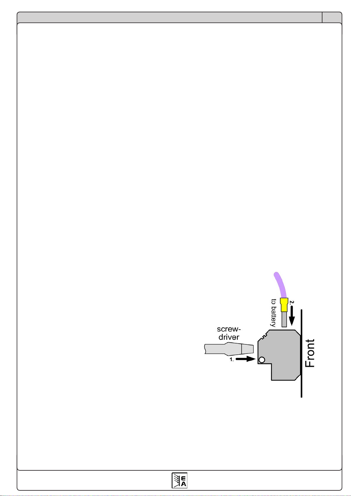
5.9.1连接
产品顶部的12针模拟接口也采用按压夹紧型端子。适合
安装0.1mm² (26 AWG)至0.5mm² (20 AWG)直径的连接
线。如果可以,线尾请套上线套。
连线夹紧步骤:

12
© 2006, Elektro-Automatik GmbH & Co. KG
Irrtümer und Änderungen vorbehalten
CN
BC 800 R 系列
产品说明书
日期:16.04.2018
操作产品
5.9.2接口引脚分布
引脚 名称 类型1描述 电平 电气参数
1 温度传感器 AO 温度传感器 LM 335 10mV/°K
2 涓充 / 电池满 A0 涓充/电池已满 充电完成 = High (UHi
g
h>4V),其它 = Low (ULow<1V)
3 充电 A0 充电激活 充电中 = High (UHi
g
h>4V), 其它 = Low (ULow<1V)
4 VMON AO 实际值:电压 0….10V相当于0….100%的UNom
5 CMON AO 实际值:电流 0….10V相当于0….100%的INom
6 AGND 模拟信号地 CMON,VMON用
7 远程 AI 远程控制激活 外部 = Low (ULow<1V),内部 = High (UHi
g
h>4V)
8 启动/停止 AI 电源模式:电源输出关闭
电池模式:启动/停止充电 关 / 启动 = Low (ULow<1V),开 / 停止 = High (UHigh>4V)
9 OT / OVP AO 过温OT / 过压OVP Low = 无错误 (ULow<1V),High = 出错 (UHigh>4V) Umax = 30V, Imax = -20mA,
准集电极
上
拉
至 Vcc 2
10 DGND 数字信号地 用来控制和监控信号
11 保留 X 不能连
12 保留 X 不能连
1) AO = 模拟输出, AI = 模拟输入
2) 12V...15V
Umax = 30V, Imax = -20mA
准集电极上拉至Vcc 2
Imax = +2mA时,精确度为0.1%,
对AGND有短路保护
Umax = 30V
Imax = -1mA@5V
5.9.3应用举例
I.开始/停止充电 (输出开/关)
远程启动充电前,需将产品设为远程控制(引脚7)。
在电池充电模式下,该引脚可开始或停止充电。
在“Power Supply Mode”下,引脚8关闭电源输出,
以及再次打开。在该模式下,无论远程是否激活,都可
使用输出,像紧急关闭开关一样。
参考脚为数字地(DGND)。
警告!如果“
Start/Stop
”引脚在转至远程控制时已下
拉,则立即开始充电。
II.监控产品状态流
输出脚为准集电极输出脚,装有一10k上拉电阻连至
Vcc。最大输入电压不能超过30V,最大输入电流不能
超过20mA。
通过该功能,在不需放大的情况下,用继电器或LED
灯指示状态。
注意:当指示特定信号时该引脚级别为HIGH。用来控
制继电器或LED灯时可能需进行相反的设置。
参考脚为数字地(DGND)。
底视图
(ADJ引脚不用)
III.监控电压和电
模拟监控输出脚输出0...10V电压,对应额定电压的
0...100%。
参考脚为模拟地(AGND)。
IV.温度感测输入脚
温度传感器放置于电池周围,或直接贴在其表面,它将
根据电池环境温度来改变充电电压。
13
BC 800 R 系列
产品说明书
CN
日期:16.04.2018
操作产品
重点是仅能使用10mV/K的传感器。允许的温度范围
为-15°C...50°C。
使用的传感器为LM335,引脚分布见上面所示。一定要
根据连线图按正确极性连接。
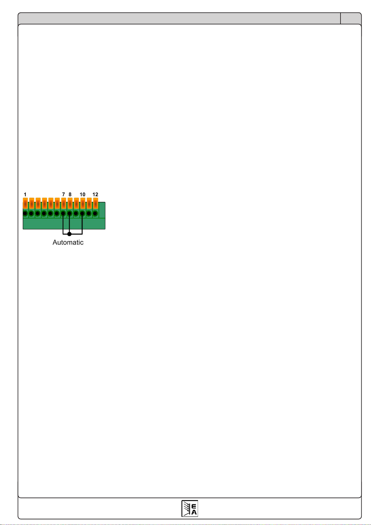
5.10激活自动充电模式
提示:自动充电模式需要先将产品转换到远程控制模
式。在远程控制模式下,不能进行任何手动控制。意
思是,若想使用限流功能
„I-Limit“
,必须预先激活它。
且要预先选择电池类型(
LEAD ACID
等)。
自动充电方式
a) 一旦接通市电,且接上电池,并无错误出现,即自
动开始充电
b) 一旦将电池接到运行中的充电器上,且无错误出现,
即自动开始充电
为了激活该模式,需在模拟接口上加跳线,如果想用手
动铠开关装置的话,也可用开关代替。用跳线时,不能
手动终止充电程序。
如果完成充电(绿灯亮),可给下一个电池充电。
注意!如果电池端同时接有负载,可能会从充电器处
吸取电流。如果吸收的电流很大,充电器会认为电池
是空的,此时它会进入快充阶段或预充模式,从而改
变输出电压。
6. 其它
6.1 重设控制面板
在很少情况下,产品对手动控制不响应,此时可重设控
制。产品启动后,按住“Charging proles”按钮即完
成。该动作会重设下列功能:
•输出关闭
•选择电源模式


15
Instruction Manual
BC 800 R Series
EN
Date: 04-16-2018
About
Elektro-Automatik GmbH & Co. KG
Helmholtzstrasse 31-37
41747 Viersen
Germany
Phone: +49 2162 / 37850
Fax: +49 2162 / 16230
Web: www.elektroautomatik.de
Mail: [email protected]
© Elektro-Automatik
Reprint, duplication or partly, wrong use of this user
instruction manual are prohibited and might be followed
by legal consequences.
Dangerous voltage
Caution: The output voltage can rise to dangerous
levels (> 60 VDC)!
All live parts have to be covered. Make sure, that the
cover is installed over the output terminals before
taking the unit into operation. All actions at the output
terminals have to be done while the unit is switched o
from the mains (mains switch OFF) and may only be
executed by personnel which is instructed about the
hazards of electrical current. Any connection between
the load and the unit (at the output terminals) have to
be scoop-proof. Applications connected to the power
output must be congured and fused in a way that
prevents the use of these to cause a damage or worse
to the unit by overload or malfunction.
Safety instructions
• The battery chargers must only charge batteries or
battery chains (parallel or series connected) that
match the device specications. The maximum
charging is identical to the nominal current, if the
limitation is not activated!
• Do not connect batteries that are not rechargeable!
• Switch device o before connecting batteries!
• The cross section of the battery cable has to match
the nominal current of the device.
• Avoid any damage to the device, do not insert metal
parts through the slots, do not obstruct the slots!
• Mains connection must only be done by trained
technical personnel.
• Mains connection only with appropriate leads and
under adherence of common safety measures.
• Avoid direct sunlight and humidity.
• When charging batteries, highly ammable gas
can emerge from the batteries. Always take care
for sucient ventilation and strictly avoid open re
and spark formation in the proximity of the batteries.

16
© 2006, Elektro-Automatik GmbH & Co. KG
Irrtümer und Änderungen vorbehalten
EN
Instruction Manual
BC 800 R Series
Date: 04-16-2018
Page
1. General ..........................................................................................................................................................17
1.1 Introduction.............................................................................................................................................17
1.2 Visual check ...........................................................................................................................................17
1.3 Scope of delivery ....................................................................................................................................17
2. Installation......................................................................................................................................................17
2.1 Mounting.................................................................................................................................................17
2.2 Mains connection....................................................................................................................................17
2.3 Sense connection ...................................................................................................................................17
2.4 DC output connection .............................................................................................................................17
2.5 Analogue interface connection ...............................................................................................................17
3. Functional description ....................................................................................................................................18
3.1 Battery types...........................................................................................................................................18
3.2 Charging procedure ...............................................................................................................................18
3.2.1 Charging characteristics...................................................................................................................18
3.3 Battery supervision .................................................................................................................................18
3.4 Temperature sensor................................................................................................................................18
3.5 Remote sense ........................................................................................................................................19
3.6 Power supply mode ................................................................................................................................19
3.7 Overvoltage protection (OVP) ...............................................................................................................19
3.8 Overtemperature (OT) ............................................................................................................................19
3.9 Errors......................................................................................................................................................19
3.10 Remote control .......................................................................................................................................19
3.11 Automatic charging mode.......................................................................................................................19
4. Technical specications .................................................................................................................................20
4.1 Dimensional drawings ............................................................................................................................21
5. Handling.........................................................................................................................................................23
5.1 Powering the device ...............................................................................................................................23
5.2 Connecting batteries...............................................................................................................................23
5.3 Selecting a battery prole .......................................................................................................................23
5.4 Start charging .........................................................................................................................................23
5.5 Stop charging .........................................................................................................................................23
5.6 Charging with reduced current ...............................................................................................................23
5.7 Parallel standby operation ......................................................................................................................24
5.8 Power Supply Mode ...............................................................................................................................24
5.9 The analogue interface ..........................................................................................................................24
5.9.1 Connection.......................................................................................................................................24
5.9.2 Pin assignment.................................................................................................................................25
5.9.3 Example applications .......................................................................................................................25
5.10 Activate automatic charging mode .........................................................................................................26
6. Miscellaneous ................................................................................................................................................26
6.1 Resetting the control panel.....................................................................................................................26
Table of contents
17
Instruction Manual
BC 800 R Series
EN
Date: 04-16-2018
1. General
1.1 Introduction
The microcontroller controlled battery chargers of the
BC 800 R series are designed for wall mount and work
with an airow based cooling.
They are intended to charge dierent type of lead
batteries. The three-stage, temperature compensating
charging procedure allows fast, complete and careful
charging of the batteries.
Furthermore, the devices feature a power supply mode
where the output voltage becomes adjustable.
The power output is protected against false polarity
connection, is short-circuit-proof and overload-proof.
For protection of the loads, the devices also feature an
overvoltage protection (OVP). At an overtemperature
(OT) event, the power output will be switched o until
the unit has cooled down and automatically switch on
again.
1.2 Visual check
After receipt, the unit has to be checked for signs of
physical damage. If any damage is found, the unit may
not be operated. Also contact your dealer immediately.
1.3 Replacing the internal fuse
Note: does not apply to model BC 812-40 R, because
here the fuse is located in a fuse holder on the front.
The main fuse is located inside the device. Before ope-
ning the device, completely disconnect it from mains.
Working on the open device must only be done by
trained technical personnel which is instructed about
the dangers and safety regulations.
In order to replace the fuse, unscrew the front cover
plate and remove it precautiously. The fuse is located
on the main PCB, on the left-hand side.
1.4 Scope of delivery
1 x Battery charger unit
1 x Printed user manual
1 x Mains connector (only with housing type 1)
1 x Temperature sensor LM335Z (10mV/K)
1 x Mounting kit (with model BC 812-40 R only)
2. Installation
2.1 Mounting
The device is designed for wall mount. It is required to
mount it in a way that allows unimpeded air ow through
the ventilation slots. Take care for plenty of space (at
least 15cm) below and above the device in order to
ensure proper cooling.
2.2 Mains connection
All models are equipped with an active PFC (power
factor correction) and a wide range input. It can be
operated at AC input voltages from 90V to 264V and
mains frequencies of 45Hz up to 65Hz.
The connection is done with the included 3-pole plug
(Phoenix Combicon GMSTB 2,5/3-ST-7,62) according
to the print on the front plate. It must only be carried
out by trained technical personnel. Main focus lies on
an appropriate cross section of the mains lead, as well
as the fact that the device does not feature a power
switch. The mains input is fused by a standard 5x20mm
fuse which is located inside the unit.
2.3 DC output and sense connection
The DC output for the battery conection and the remote
sense inputs are located on the front. Except for model
BC 812-40 R, these are all of the same type (press &
clamp). Cable cross section goes from 0.08mm² (28
AWG) to 4mm² (12 AWG). If possible, use cable end
sleeves.
Clamping procedure:
With model BC 812-40 R, the battery is connected via
screw terminal
2.4 Analogue interface connection
See section „5.9 The analogue interface“.
About the device
18
© 2006, Elektro-Automatik GmbH & Co. KG
Irrtümer und Änderungen vorbehalten
EN
Instruction Manual
BC 800 R Series
Date: 04-16-2018
3. Functional description
3.1 Battery types
The battery chargers can be used to charge dierent
types of lead batteries, as for example lead-acid, gel
cell or AGM type. Any of the battery types are charged
according to a three-stage, temperature compensating
(only with temperature sensor connected) charging
procedure. The battery type can be selected by a push-
button on the front panel. The related charging proles
mainly dier in the cell voltage (see table below).
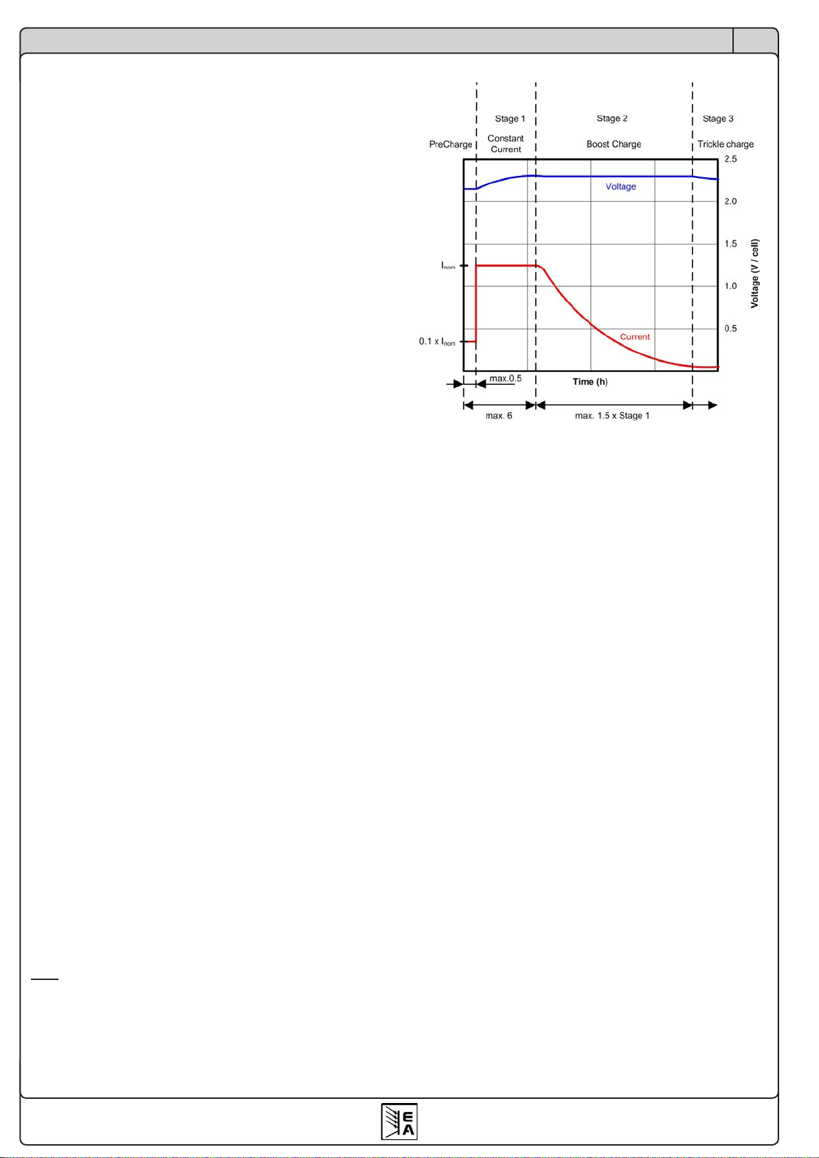
3.2 Charging procedure
Attention! Defective batteries (UBatAct = <0.4 x UBatNom)
can not be charged!
The charging procedure follows an I-U-U characteri-
stics.
In the first phase of the charging the battery is
precharged with reduced output current (0.1 x INom).
The precharge is very eective on deeply discharged
batteries with UBatAct = >0.4 x UBatNom, providing the
possibility to repair and recharge them again. As soon
as the output voltage rises to 0.9 x UBatNom or after a
maximum precharge time of 30 minutes, the procedure
changes to normal charge phase. Precharge and nor-
mal charge are indicated by the red LED of the trac
light type display.
During normal charge, the battery is charged with full
output current INom (or with a reduced to 30% output
current I-Limit).
After leaving the constant current charging or after a
maximum 6 hours charging time, the charging proce-
dure changes to boost charge (yellow LED).
Boost charge is done with increased charging voltage.
As soon as the charging current becomes <5% of INom
or the boost charge phase time exceeds 1.5 times the
time of the normal charge phase, the charging proce-
dure changes to trickle charge.
When reached and if the charging current remains
below 5% INom, the battery is indicated as fully charged
by the green status LED.
During trickle charge, the battery is kept charged with
trickle charge voltage for an unlimited time, unless char-
ging is stopped or interrupted by any error or blackout.
Boost charge and trickle charge make use the tem-
perature compensation, which is recommend in order
to prevent the batteries from gassing.
Tip: it is possible to manually reduce the output current
by activating the 30% I-Limit. This is done by pressing
the pushbutton „Charging Proles“ longer than 3s.
The I-Limit is useful when charging small batteries that
require lower charging currents.
3.2.1 Charging characteristics
3.3 Battery supervision
The battery or batteries are connected to the desi-
gnated terminal „Battery“ on the front. The output is
supervised for false polarity and wrong battery voltage.
In case the battery was connected with false polarity,
the battery voltage is too low or too high, the charging
is inhibited to start.
Attention! Only connect batteries whose battery volta-
ge matches the nominal charging voltage of the device.
Else the battery and/or the device might get damaged.
3.4 Temperature sensor
It is recommended to use temperature compensation
when charging batteries, in order to prevent dangerous
gassing.
Without the temperature sensor the batteries are
charged with voltages that correspond to an ambient
temperature of 25°C. The sensor is directly connected
to pins 1 and 6 of the analogue interface and has to
be placed in proximity of the battery or attached to the
battery. It is detected and used when the charging is
started. If the device measures temperatures above
+50°C, the charging is paused After cooling down to
<+45°C, the charging is automatically continued. This
only works if the temperature sensor is attached. The
error LED will only ash as long the battery overtem-
perature error persists.
At temperatures below -15°C, the temperature com-
pensation will halt. In case the sensor is removed
during charging or if damaged, the device continues
the charging procedure with a charge phase voltage
corresponding to 25°C.
Functional description

19
Instruction Manual
BC 800 R Series
EN
Date: 04-16-2018
In order for the user to notice temperature related er-
rors, the LED keeps ashing even if the temperature
is within the normal range again. Starting the charging
again or switching to power supply mode will erase
the error and LED will stop ashing, if the temperature
is OK.
Temperature sensors of type LM335 or similiar, which
are specied with 10mV/K temperature voltage, can
be used. Pin 1 delivers approx. 4.1V and currents from
0.8mA (internal 1k in series to the temp sensor).
The temperature compensation of the charging voltage
is done with 4mV/°C and per battery cell.
3.5 Remote sense
In order to compensate voltage drops along the load
leads, the device features remote sense inputs on
the front. Here the sensed voltage from the battery
is connected with correct polarity. Remote sense can
compensate up to 2V.
When not using the sense inputs, they just remain open.
It is not required to bridge them to the output.
The cross section of the sense leads is non-critical.
3.6 Power supply mode
The device can be used as power supply, if „Power
Supply Mode“ has been selected with the „Charging
proles“ button. In this mode, the output voltage can
then be adjusted with the trimmer within a limited range
(see „4. Technical specications“). It either works in
constant voltage or in constant current operation (U-I
characteristics), , displayed by the green or red LED
on the front panel.
This mode is suitable for parallel standby operation,
also see „5.7 Parallel standby operation“.
3.7 Overvoltage protection (OVP)
All models feature an overvoltage protection circuit. In
case of an overvoltage condition, whether caused by an
internal defect or by external reasons, the power output
is switched o and the error is indicated by ashing LED
„Error“ and also by pin 9 of the analogue interface. After
the OV condition is gone, the output can be switched
on resp. the charging can be started again.
3.8 Overtemperature (OT)
All models also feature an internal temperature super-
vision. In case of overheating, the power output will
be temporarily switched o until the device has cooled
down, and then automatically switch on again.
Charging is thus only interrupted, but not stopped. The
condition is indicated by ashing LED „Error“ and by
pin 9 of the analogue interface.
Functional description
3.9 Errors
Any error is indicated by ashing LED „Error“. Following
general errors can be signaled:
• Overvoltage (OVP)
• Overtemperature (OT)
• Battery connected with false polarity
The errors OVP and OT are also indicated at the ana-
logue interface.
In battery charger mode, i.e. not in power supply mode,
following additional errors can be signalled:
• Connection of battery with too low or too high voltage
• Temperature sensor failure (broken wire etc.)
3.10 Remote control
All models feature a 12 pin analogue interface on the
front of the device. It can be used to monitor the device
condition, as well as remotely start/stop the charging
procedure. Also see section 5.9 and up.
3.11 Automatic charging mode
This extra mode can be activated to start charging of
batteries automatically after mains supply is switched
on or if a battery is connected. For details see „5.10
Activate automatic charging mode“.

20
© 2006, Elektro-Automatik GmbH & Co. KG
Irrtümer und Änderungen vorbehalten
EN
Instruction Manual
BC 800 R Series
Date: 04-16-2018
Handling the device
4. Technical specications
BC 812-20
R
BC 824-10
R
BC 848-05
R
BC 812-40
R
BC 824-20
R
BC 848-10
R
Mains input
Input voltage 90…264V 90…264V 90…264V 90…264V 90…264V 90…264V
Frequency 45…65Hz 45…65Hz 45…65Hz 45…65Hz 45…65Hz 45…65Hz
Power factor correction >0.99 >0.99 >0.99 >0.99 >0.99 >0.99
Input current at 230V 1.6A 1.6A 1.6A 3.4A 3.2A 3.2A
Fuse M6.3A M6.3A M6.3A T10A T10A T10A
Output - Voltage
Battery voltage U
Bat
12V 24V 48V 12V 24V 48V
Adjustable range 10…15V 20…30V 40…60V 10…15V 20…30V 40…60V
Stability at 10-90% load <0.05% <0.05% <0.05% <0.05% <0.05% <0.05%
Stability at ±10% ∆U
In
<0.02% <0.02% <0.02% <0.02% <0.02% <0.02%
Ripple <40mV
PP
<100mV
PP
<150mV
PP
<10mV
PP
<100mV
PP
<150mV
PP
Regulation 10-100% load <2ms <2ms <2ms <2ms <2ms <2ms
Output - Current
Nominal current 20A 10A 5A 40A 20A 10A
Stability at 0-100% ∆U
Out
<0.15% <0.15% <0.15% <0.15% <0.15% <0.15%
Stability at ±10% ∆U
In
<0.05% <0.05% <0.05% <0.05% <0.05% <0.05%
Ripple <60mA
PP
<35mA
PP
<12mA
PP
<19mA
PP
<65mA
PP
<25mA
PP
Output - Power
Nominal power 300W 300W 300W 600W 600W 600W
Miscellaneous
Operation temperature 0…50°C 0…50°C 0…50°C 0…50°C 0…50°C 0…50°C
Storage temperature -20…70°C -20…70°C -20…70°C -20…70°C -20…70°C -20…70°C
Humidity <80% <80% <80% <80% <80% <80%
Dimensions (WxHxD) 218x83x163mm 218x83x163mm 218x83x163mm 90x360x240mm 218x83x163mm 218x83x163mm
Weight 2.2kg 2.2kg 2.2kg 6.5kg 2.2kg 2.2kg
Article No. 27150311 27150312 27150313 27150316 27150314 27150315
Safety
EMC standards
Overvoltage category
Protection class
EN 60950
EN 61326, EN 550022 Class B
Class II
Class I
This manual suits for next models
12
Table of contents


