manuals.online logo
Brands
  1. Home
  2. •
  3. Brands
  4. •
  5. Electro-Voice
  6. •
  7. Speakers
  8. •
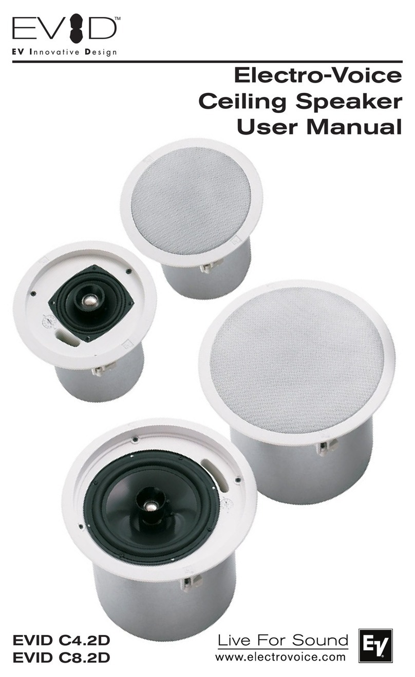
  9. Electro-Voice EVID Series User manual

Electro-Voice EVID Series User manual

Other manuals for EVID Series

3

This manual suits for next models

18

Other Electro-Voice Speakers manuals

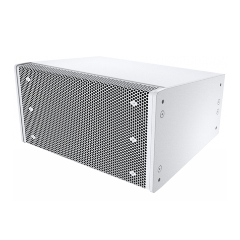
Electro-Voice Xi Series Xi-1152A/94F User manual

Electro-Voice

Electro-Voice Xi Series Xi-1152A/94F User manual

Electro-Voice 10BX User manual

Electro-Voice

Electro-Voice 10BX User manual

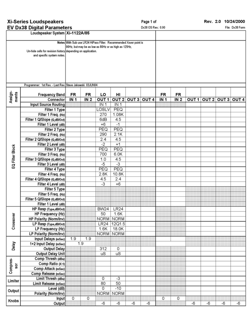
Electro-Voice Michigan MC12 Dimension Guide

Electro-Voice

Electro-Voice Michigan MC12 Dimension Guide

Electro-Voice X-Array XF User manual

Electro-Voice

Electro-Voice X-Array XF User manual

Electro-Voice SX Series SX600 User manual

Electro-Voice

Electro-Voice SX Series SX600 User manual

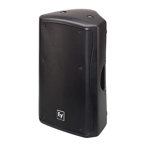
Electro-Voice EV ZX5-60 User manual

Electro-Voice

Electro-Voice EV ZX5-60 User manual

Electro-Voice Xlc Series Xlc-127DVX User manual

Electro-Voice

Electro-Voice Xlc Series Xlc-127DVX User manual

Electro-Voice LiveX ELX112 User manual

Electro-Voice

Electro-Voice LiveX ELX112 User manual

Electro-Voice pim-252 User manual

Electro-Voice

Electro-Voice pim-252 User manual

Electro-Voice EVX150 Mounting instructions

Electro-Voice

Electro-Voice EVX150 Mounting instructions

Electro-Voice EVID C8.2HC User guide

Electro-Voice

Electro-Voice EVID C8.2HC User guide

Electro-Voice XLC118 User manual

Electro-Voice

Electro-Voice XLC118 User manual

Electro-Voice Eliminator i User manual

Electro-Voice

Electro-Voice Eliminator i User manual

Electro-Voice EVID C12.2 User manual

Electro-Voice

Electro-Voice EVID C12.2 User manual

Electro-Voice Zx1i-90 User manual

Electro-Voice

Electro-Voice Zx1i-90 User manual

Electro-Voice XLC118 User manual

Electro-Voice

Electro-Voice XLC118 User manual

Electro-Voice Xi Series Xi-1183A/64F Manual

Electro-Voice

Electro-Voice Xi Series Xi-1183A/64F Manual

Electro-Voice SxA360 User manual

Electro-Voice

Electro-Voice SxA360 User manual

Electro-Voice EKX-15P User manual

Electro-Voice

Electro-Voice EKX-15P User manual

Electro-Voice Xw15A Manual

Electro-Voice

Electro-Voice Xw15A Manual

Electro-Voice DeltaMax DML-1122 User manual

Electro-Voice

Electro-Voice DeltaMax DML-1122 User manual

Electro-Voice ZXA5-60 User manual

Electro-Voice

Electro-Voice ZXA5-60 User manual

Electro-Voice EVID C8.2HC User manual

Electro-Voice

Electro-Voice EVID C8.2HC User manual

Electro-Voice Xlc Series Xlc-127DVX User manual

Electro-Voice

Electro-Voice Xlc Series Xlc-127DVX User manual

Popular Speakers manuals by other brands

Definitive Technology Sound Cylinder user guide

Definitive Technology

Definitive Technology Sound Cylinder user guide

AudioSource LS545 user manual

AudioSource

AudioSource LS545 user manual

Paso C402-T Instructions for use

Paso

Paso C402-T Instructions for use

Altec Lansing 416-8C LF SPEAKER manual

Altec Lansing

Altec Lansing 416-8C LF SPEAKER manual

Kenwood KFC-1072 Servise manual

Kenwood

Kenwood KFC-1072 Servise manual

Peavey ProSys 112 user guide

Peavey

Peavey ProSys 112 user guide

JBL Control Contractor 60 Series installation instructions

JBL

JBL Control Contractor 60 Series installation instructions

Aura STORM-8 owner's manual

Aura

Aura STORM-8 owner's manual

Oontz ANGLE 3 PLUS quick start guide

Oontz

Oontz ANGLE 3 PLUS quick start guide

Rave RK-650-ICA-B owner's manual

Rave

Rave RK-650-ICA-B owner's manual

Flux Reference Series installation manual

Flux

Flux Reference Series installation manual

Lanzar AQAWBS64BK installation manual

Lanzar

Lanzar AQAWBS64BK installation manual

DAPAudio DCS-6230 manual

DAPAudio

DAPAudio DCS-6230 manual

Aluratek ABS03F quick start guide

Aluratek

Aluratek ABS03F quick start guide

Kenwood KES-5A instruction manual

Kenwood

Kenwood KES-5A instruction manual

Sonance ORIGINAL SERIES instruction manual

Sonance

Sonance ORIGINAL SERIES instruction manual

Empire S-5000 user manual

Empire

Empire S-5000 user manual

Marshall Amplification Stanmore II Voice with Amazon Alexa user manual

Marshall Amplification

Marshall Amplification Stanmore II Voice with Amazon Alexa user manual

manuals.online logo
manuals.online logoBrands
  • About & Mission
  • Contact us
  • Privacy Policy
  • Terms and Conditions

Copyright 2025 Manuals.Online. All Rights Reserved.


Owner’s Manual
Owner’s Manual

TOC
TOC
TTable able of of ContentsContents............................................................ TOCTOC
SafeSafety ty FirstFirst .......................................................................... TOCTOC
ProduProduct ct DescrDescriptioniption ..............................................................11
WelcomeWelcome .............................................................................................. 11
ImporImportant tant FeatuFeaturesres ..............................................................11
Model SuModel Summarymmary ......................................................................22
PackiPacking ng ListList .................................................................................... 22
EVIDEVIDTMTMProduct FamilyProduct Family ..................................................33
ProduProduct Feature Idenct Feature Identificatificationtion ............................33
SAMSAMTMTM(Strong-Arm-Mount(Strong-Arm-MountTMTM) ) SSysystetemm..44
StepStep-by-Step -by-Step Installation Installation and and WiringWiring ........ 44
Step 1 - Mount the SAMStep 1 - Mount the SAMTMTMBrBracackekett..4..4
Step 2 - Select Wattage Tap (ModelsStep 2 - Select Wattage Tap (Models
4.2t 4.2t and and 6.2t 6.2t OnlyOnly))........................................................ 55
Step 3 - Mount the Speaker to theStep 3 - Mount the Speaker to the
SAMSAMTMTMBraBracketcket ..................................................................55
SStep 4 - Wire the Spetep 4 - Wire the Speakeraker ................................ 66
Step 5 - Secure the Seismic TabStep 5 - Secure the Seismic Tab
ConnConnection ection PoinPointt............................................................ 66
SStep 6 - Ttep 6 - Test Systest System Operaem Operationtion ..............66
PackPacking List (1ing List (12.1 Sub2.1 Subwoofwoofer)er) ..........................77
Product Feature Identification (12.1Product Feature Identification (12.1
SubwSubwoofeoofer)r) ......................................................................................77
Step-byStep-by-Step Installation and -Step Installation and WiringWiring
(12.1 (12.1 SubwSubwoofeoofer)r) ....................................................................88
SStep 1 tep 1 - Moun- Mount the Bt the Brackracketet ............................88
SStep 2 - Insttep 2 - Install the Saall the Safety Lifety Linene .................. 88
SStep 3 - Wire the Spetep 3 - Wire the Speakeraker ................................ 88
EVIDEVIDTMTMOwner’s ManualOwner’s Manual
Table of ContentsTable of Contents
Step 4 - Mount the Speaker to theStep 4 - Mount the Speaker to the
BrackBracketet ..........................................................................................99
SStep 5 - Ttep 5 - Test Systeest System Operatiom Operationn..........1010
SafetSafety Agey Agency Complincy Complianceance ................................ 1010
MainteMaintenancenance ..............................................................................1010
UnifoUniform Limited Wrm Limited Warranarrantyty ......................................1111
ExclExclusionusions s and Limitationand Limitationss.................................. 1111
ObtaObtaining Wining Warrantarranty Servicy Servicee..............................1111
Incidental and Consequential DamagesIncidental and Consequential Damages
ExclExcludeduded .......................................................................................... 1111
Other RighOther Rightsts ..............................................................................1111
SSpeakpeakers aners and Electd Electronicsronics .................................... 1111
Appendix A - Integrating the 12.1Appendix A - Integrating the 12.1
SubwooferSubwoofer ..........................................................................................1212
InstInstallatiallation Exampleon Exampless..................................................1212
Using Using the 12the 12.1 in P.1 in Passivassive Mode Modee................1212
CrossCrossover over Freq. Freq. and and ImpedImpedanceance ..............1212
Using a Separate Amplifier Channel forUsing a Separate Amplifier Channel for
the the 12.112.1 .............................................................................................. 1212
CharaCharacteriscteristics of tics of All SubAll Subwoofewoofersrs ............1212
AppenAppendix B dix B - Pain- Painting thting the Se Speakepeakerr........ 1313
PainPainting Pting Procesrocess (3.s (3.2, 4.22, 4.2, 6.2), 6.2) ..................1313
PaintPainting the Grilleing the Grille ..............................................................1313
PainPainting ting ProceProcess (1ss (12.1 S2.1 Subwoubwoofer)ofer) ......1313
AppenAppendix C - Tdix C - Troublroubleshooeshooting Tting Tableable ..1414
AppenAppendix D - Tedix D - Technicchnical Speal Specscs ........................1515
3.2/3.2/3.2t; 4.2/4.23.2t; 4.2/4.2tt..................................................................1515
6.2/66.2/6.2t; 12.1.2t; 12.1 ............................................................................1616
NoteNotess............................................................................................................1717
Safety FirstSafety First
Suspending any object is potentially dangerous and should only Suspending any object is potentially dangerous and should only be attempted by individuals whobe attempted by individuals who
have a thorough knowledge of the techniques and have a thorough knowledge of the techniques and regulations of rigging objects overhead. Electro-regulations of rigging objects overhead. Electro-
VVoice® strongly recommends that all speakers be oice® strongly recommends that all speakers be suspended taking into account all current national,suspended taking into account all current national,
federal, state and local regulations. It is federal, state and local regulations. It is the responsibility of the installer to ensure that the responsibility of the installer to ensure that all speakersall speakers
are safely installed in accordance with all are safely installed in accordance with all such regulations. When speakers are suspended, Electro-such regulations. When speakers are suspended, Electro-
VVoice® strongly recommends thaoice® strongly recommends that the system be inspected at least once a yeart the system be inspected at least once a year. . If any sign ofIf any sign of
weakness or damage is detected, remedial action should weakness or damage is detected, remedial action should be taken immediatelybe taken immediately. The user is. The user is
responsible for making sure that the responsible for making sure that the supporting surfaces, and any additional hardware used, issupporting surfaces, and any additional hardware used, is
capable of supporting the loudspeakercapable of supporting the loudspeaker. . Any hardware used to suspend a loudspeaker array that isAny hardware used to suspend a loudspeaker array that is
not provided by/associated with Electro-Voice® is the responsibility of not provided by/associated with Electro-Voice® is the responsibility of others.others.


EVID
EVIDTMTMOwner’s ManualOwner’s Manual 11
Product DescriptionProduct Description
WelcomeWelcome
Thank you for purchasing EVID™ SeriesThank you for purchasing EVID™ Series
loudspeakers. Read through this manualloudspeakers. Read through this manual
to familiarize yourself with the features,to familiarize yourself with the features,
applications, and precautions before youapplications, and precautions before you
use these products.use these products.
EVID™ Series loudspeakers useEVID™ Series loudspeakers use
innovative design and materials to provideinnovative design and materials to provide
premium-level performance from compactpremium-level performance from compact
surface-mount speakers.surface-mount speakers.
Four models comprise the EVID™ Series:Four models comprise the EVID™ Series:
the 6.2 with dual 6-inch LF drivers and a 1-the 6.2 with dual 6-inch LF drivers and a 1-
inch titanium tweeter with waveguide; theinch titanium tweeter with waveguide; the
4.2 with dual 4-inch LF drivers and a 1-4.2 with dual 4-inch LF drivers and a 1-
inch titanium tweeter with waveguide; theinch titanium tweeter with waveguide; the
3.2 with dual 3.5-inch LF drivers and a .75-3.2 with dual 3.5-inch LF drivers and a .75-
inch titanium direct radiator tweeter. Theinch titanium direct radiator tweeter. The
EVID™ 12.1, a subwoofer designed toEVID™ 12.1, a subwoofer designed to
augment and extend the full-range model’saugment and extend the full-range model’s
low-frequency response completes thelow-frequency response completes the
line.line.
Important FeaturesImportant Features
••LinLine-ae-arrarray eny enhanhanced ced covcoveraerage cge contontrolrol
••OrOrgaganinic, uc, unonobtbtrurusisive sve shahapepe
••SAMSAM™ (™ (SStrotrong-ng-ArmArm-Mo-Mountunt™) s™) systystemem
for secure and reliable mountingfor secure and reliable mounting
••ExtExtremremely ely larlarge ge spespeakeaker sr swinwing ag andnd
rotation ranges for flexible placementrotation ranges for flexible placement
and coverage everywhereand coverage everywhere
••FulFull bal bandwndwidtidth oh oververloaload pd proterotectictionon
••WeWeathather rer resiesiststant ant and and papaintintablablee
••DuDual al LF LF trtranansdsducucererss
••EExxtteennddeed bd baassss
••GreGreateater por power wer hanhandlidling ang and ond outputputut
••TTitaitaniunium HF m HF tratransdnsduceucers (rs (4.24.2, 6., 6.22
waveguide coupled)waveguide coupled)
••HHigigh seh sensnsititivivitityy
••ShiShieldelded ed for for vidvideo eo appappliclicatiationsons

EVID
EVIDTMTMOwner’s ManualOwner’s Manual
22
Product DescriptionProduct Description
eerruuggiiF F yyttiittnnaauuQ Q ttrraaPP
A A 2 2 mmeettssyySSrreekkaaeeppSS
B B 2 2 MMAASSMMTTyyllbbmmeessssAA
C C 2 2 ppaaCCooggooLLeeggrraaLL
C C 2 2 ppaaCCooggooLLllllaammSS
D D 1 1 llaauunnaaMMss''rreennwwOO
E E 1 1 ddrraaCCyyttnnaarrrraaWW
F F 1 1 MMAASSMMTTllooooTTggnniittnnuuooMM
Figure 1:Figure 1: EVIDEVIDTMTMComponentsComponents
Model SummaryModel Summary
EVID™ 3.2EVID™ 3.2
Most compact of the EVID™ Series, theMost compact of the EVID™ Series, the
EVID™ 3.2 uses dual 3.5-inch LF driversEVID™ 3.2 uses dual 3.5-inch LF drivers
with a .75-inch titanium direct radiatorwith a .75-inch titanium direct radiator
tweeter to provide high-fidelity, full-rangetweeter to provide high-fidelity, full-range
sound over an extremely wide sound over an extremely wide coveragecoverage
area. The EVID™ 3.2t includes aarea. The EVID™ 3.2t includes a
transformer for 70V or 100V systems.transformer for 70V or 100V systems.
EVID™ 4.2EVID™ 4.2
The compact EVID™ 4.2 delivers very full-The compact EVID™ 4.2 delivers very full-
range sound from its dual 4-inch LFrange sound from its dual 4-inch LF
drivers and a 1-inch titanium tweeter withdrivers and a 1-inch titanium tweeter with
waveguide. It is able to deliver a 110-dBwaveguide. It is able to deliver a 110-dB
sound level over a wide coverage area.sound level over a wide coverage area.
The EVID™ 4.2t includes a multi-tapThe EVID™ 4.2t includes a multi-tap
transformer for 70V or 100V line distribu-transformer for 70V or 100V line distribu-
tion systems.tion systems.
EVID™ 6.2EVID™ 6.2
The EVID™ 6.2 is an extended-rangeThe EVID™ 6.2 is an extended-range
high-output speaker with dual 6.5-inchhigh-output speaker with dual 6.5-inch
woofers and a 1-inch titanium tweeter withwoofers and a 1-inch titanium tweeter with
waveguide, designed for high SPL over awaveguide, designed for high SPL over a
wide coverage area. The EVID™ 6.2twide coverage area. The EVID™ 6.2t
includes a multi-tap transformer for a 70Vincludes a multi-tap transformer for a 70V
or 100V line distribution system.or 100V line distribution system.
EVID™ 12.1EVID™ 12.1
This subwoofer’s unique 12-inch dual-This subwoofer’s unique 12-inch dual-
voice-coil woofer design and side/frontvoice-coil woofer design and side/front
angled port system allows for powerfulangled port system allows for powerful
low-frequency reinforcement from alow-frequency reinforcement from a
flexible, compact wall- or ceiling-mountedflexible, compact wall- or ceiling-mounted
enclosure. The EVID™ 12.1's full, richenclosure. The EVID™ 12.1's full, rich
bass is an ideal addition to any EVID™bass is an ideal addition to any EVID™
system.system.
Packing List (3.2, 4.2, 6.2)Packing List (3.2, 4.2, 6.2)
Listed and illustrated below are the partsListed and illustrated below are the parts
included in each boxed pair of EVID™included in each boxed pair of EVID™
speakers.speakers.
AA
BB
CC
EED D FF

EVID
EVIDTMTMOwner’s ManualOwner’s Manual 33
Product DescriptionProduct Description
EEVVIIDD™ ™ PPrroodduucct t FFaammiillyyPPrroodduucct t FFeeaattuurre e IIddeennttiiffiiccaattiioonn
Illustrated below are the major compo-Illustrated below are the major compo-
nents of the EVID™ Series full-rangenents of the EVID™ Series full-range
speakers.speakers.
Figure 2:Figure 2: EVIDEVIDTMTMFeatures (Front)Features (Front)
Figure 3:Figure 3: EVIDEVIDTMTMFeatures (Back)Features (Back)
A.A. ShShieieldlded ed dudual al wowoofofererss
B.B. CohCohereerent Covnt Coveraerage Wge Wavavegueguide hoide hornrn
(4.2 and 6.2 only)(4.2 and 6.2 only)
CC..DuDual loal low-w-frfreqequeuencncy porty portss
DD..TTrereatated wed wooooffer coer coneness
E.E. DurabDurable zle zinc-pinc-plated lated steel steel grillgrille (ne (not sot shownhown))
FF..CasCast alut aluminminum Stum Stronrong-Ag-Arm-Mrm-Mounount™ (SAt™ (SAM™)M™)
G.G. OveOver 100 r 100 degredegrees of es of swiswing; ng; 90 de90 degreesgrees
of rotationof rotation
H.H. SimplSimple ke keyeyed sed sockocket het head ead adjusadjustmenttmentss
I.I. TiTitataninium doum dome twme tweeeeteters wirs with neth neododymymiuiumm
magnet structuresmagnet structures
AA
IIHH
GG
FF
(E)(E)
DD
CC
BB
eeccnnaaddeeppmmIImmhhoo--88
..ooNNttrraaP P lleeddooM M nnooiittppiirrccsseeDD
110000--55440011003 3 22..33eeggnnaaRR--lllluuFF""55..33llaauuDD))kkccaallBB((ddeeddlleeiihhSS
220000--55440011003 3 ww22..33eeggnnaaRR--lllluuFF""55..33llaauuDD
))eettiihhWW((ddeeddlleeiihhSS
110000--66440011003 3 22..44eeggnnaaRR--lllluuFF""44llaauuDD
))kkccaallBB((ddeeddlleeiihhSS
220000--66440011003 3 ww22..44eeggnnaaRR--lllluuFF""44llaauuDD
))eettiihhWW((ddeeddlleeiihhSS
110000--77440011003 3 22..66eeggnnaaRR--lllluuFF""66llaauuDD
))kkccaallBB((ddeeddlleeiihhSS
220000--77440011003 3 ww22..66eeggnnaaRR--lllluuFF""66llaauuDD
))eettiihhWW((ddeeddlleeiihhSS
ssttiinnUUddeeppppiiuuqqEEttllooVV--000011//ttllooVV--0077
..ooNNttrraaP P lleeddooM M nnooiittppiirrccsseeDD
330000--55440011003 3 tt22..33eeggnnaaRR--lllluuFF""55..33llaauuDD
))kkccaallBB((ddeeddlleeiihhSS
440000--55440011003 3 wwtt22..33eeggnnaaRR--lllluuFF""55..33llaauuDD
))eettiihhWW((ddeeddlleeiihhSS
330000--66440011003 3 tt22..44eeggnnaaRR--lllluuFF""44llaauuDD
))kkccaallBB((ddeeddlleeiihhSS
440000--66440011003 3 wwtt22..44eeggnnaaRR--lllluuFF""44llaauuDD
))eettiihhWW((ddeeddlleeiihhSS
330000--77440011003 3 tt22..66
eeggnnaaRR--lllluuFF""66llaauuDD
))kkccaallBB((ddeeddlleeiihhSS
440000--77440011003 3 wwtt22..66eeggnnaaRR--lllluuFF""66llaauuDD
))eettiihhWW((ddeeddlleeiihhSS
ssrreeffoooowwbbuuSS
..ooNNttrraaP P lleeddooM M nnooiittppiirrccsseeDD
110000--88440011003 3 11..2211ttuuppnnIIllaauuDD""2211
))kkccaallBB((
220000--88440011003 3 ww11..2211ttuuppnnIIllaauuDD""2211
))eettiihhWW((

EVID
EVIDTMTMOwner’s ManualOwner’s Manual
44
Figure 4:Figure 4: Rotation Rotation Range Range (90°(90°))
Product DescriptionProduct Description
SAM™ (Strong-Arm-SAM™ (Strong-Arm-
Mount™) SystemMount™) System
EVID™’s SAM™ system (Strong-Arm-EVID™’s SAM™ system (Strong-Arm-
Mount™) excels at meeting the fourMount™) excels at meeting the four
requirements for mounting FGM/BGMrequirements for mounting FGM/BGM
systems: simple, quick, versatile, andsystems: simple, quick, versatile, and
reliable. Three easy steps and you arereliable. Three easy steps and you are
done: Attach the surface bracket to thedone: Attach the surface bracket to the
wall or ceiling; attach the EVID™wall or ceiling; attach the EVID™
enclosure to the bracket with the socket-enclosure to the bracket with the socket-
head bolt; aim the enclosure and tightenhead bolt; aim the enclosure and tighten
the bolt. SAM™ allows greater flexibilitythe bolt. SAM™ allows greater flexibility
for aiming than ball-type mounts that limitfor aiming than ball-type mounts that limit
range of motion when not on center.range of motion when not on center.
Typical ball designs have limited rotationTypical ball designs have limited rotation
when pointing straight ahead, and evenwhen pointing straight ahead, and even
that is reduced when the enclosurethat is reduced when the enclosure
contacts the wall and is moved off axis. Bycontacts the wall and is moved off axis. By
contrast, SAM™ allows full rotation evencontrast, SAM™ allows full rotation even
at full sweep. Figure 4 shows SAM™’sat full sweep. Figure 4 shows SAM™’s
range of rotation (note that EVID™’srange of rotation (note that EVID™’s
curved cabinet allows it to rotate muchcurved cabinet allows it to rotate much
further further [90°[90°] than a r] than a rectangular ectangular oror
trapezoidal box). Figure 5 shows the rangetrapezoidal box). Figure 5 shows the range
of sweep motion left and right on the wall.of sweep motion left and right on the wall.
All threAll three models ale models allow 100° low 100° of sidewiof sidewisese
motion.motion.
Step-by-Step InstallationStep-by-Step Installation
and Wiring (3.2, 4.2, 6.2)and Wiring (3.2, 4.2, 6.2)
Step 1: Mount the SAM™ BracketStep 1: Mount the SAM™ Bracket
to the Wallto the Wall
The SAM™ bracket can be mounted onThe SAM™ bracket can be mounted on
either side of the speaker, enablingeither side of the speaker, enabling
optimal configuration for any installation.optimal configuration for any installation.
Determine whether the bracket should beDetermine whether the bracket should be
mounted on the left or right side of themounted on the left or right side of the
speaker before you bolt the speaker tospeaker before you bolt the speaker to
the bracket. It is best to mount the bracketthe bracket. It is best to mount the bracket
on the side away from the direction inon the side away from the direction in
which the speaker will be aimed. Thiswhich the speaker will be aimed. This
ensures that the full swing angle isensures that the full swing angle is
available for aiming on that side andavailable for aiming on that side and
provides easier access to the swingprovides easier access to the swing
tightening bolt on the wall bracket (seetightening bolt on the wall bracket (see
Fig. 10, Step 3). For safety, make sure theFig. 10, Step 3). For safety, make sure the
mounting surface can support more thanmounting surface can support more than
the speaker's weight! Use only industry-the speaker's weight! Use only industry-
accepted fasteners and mountingaccepted fasteners and mounting
methods when mounting the bracket.methods when mounting the bracket.
Consult an expert if you are not sure.Consult an expert if you are not sure.
Read steps 2 and 3 before wiring theRead steps 2 and 3 before wiring the
speaker in step 4.speaker in step 4.
For standard vertical installation mount theFor standard vertical installation mount the
SAM™ bracket as shown in Figure 6. ForSAM™ bracket as shown in Figure 6. For
horizontal mounting configurations,horizontal mounting configurations,
mounting the bracket on the bottom sidemounting the bracket on the bottom side
(as in Figure 7) is easiest and safest, and(as in Figure 7) is easiest and safest, and
allows the speaker to be mounted closerallows the speaker to be mounted closer
to the ceiling.to the ceiling.
Figure 6:Figure 6: SAMSAMTMTMMounted on SideMounted on Side
Figure 5:Figure 5: Sweep Sweep Range Range (100°(100°))Figure 7:Figure 7: SAMSAMTMTMMounted on BottomMounted on Bottom
90˚90˚
100˚100˚
SAM™SAM™
SAM™SAM™
CeilingCeiling

EVID
EVIDTMTMOwner’s ManualOwner’s Manual 55
Figure 8:Figure 8: Wattage Taps (4.2t & 6.2t)Wattage Taps (4.2t & 6.2t)
Product DescriptionProduct Description
Step 2: Select Wattage TapStep 2: Select Wattage Tap
(Models 4.2t and 6.2t Only)(Models 4.2t and 6.2t Only)
Before mounting the speaker to theBefore mounting the speaker to the
bracket, select the proper wattage tapbracket, select the proper wattage tap
setting for your installation. The wattagesetting for your installation. The wattage
selector switch is located at the rear of theselector switch is located at the rear of the
speaker below the input terminal panel.speaker below the input terminal panel.
The EVID™ 4.2t and 6.2t include a switchThe EVID™ 4.2t and 6.2t include a switch
for selecting the power taps. The EVID™for selecting the power taps. The EVID™
3.2t has a single power tap.3.2t has a single power tap.
EVID™ 3.2tEVID™ 3.2t
A single (non-selectable) power tap ratedA single (non-selectable) power tap rated
at 5W@70V and 10W@100V.at 5W@70V and 10W@100V.
EVID™ 4.2tEVID™ 4.2t
The power taps are 30W, 15W and 7.5WThe power taps are 30W, 15W and 7.5W
at both 70.7V and 100V, with a 3.7W tapat both 70.7V and 100V, with a 3.7W tap
for 70.7V only, as well as an 8 ohmfor 70.7V only, as well as an 8 ohm
transformer bypass setting.transformer bypass setting.
EVID™ 6.2t:EVID™ 6.2t:
The power taps are 60W, 30W and 15WThe power taps are 60W, 30W and 15W
at both 70.7V and 100V, with a 7.5W tapat both 70.7V and 100V, with a 7.5W tap
for 70.7V only, as well as an 8 ohmfor 70.7V only, as well as an 8 ohm
transformer bypass setting.transformer bypass setting.
The taps for the models listed above areThe taps for the models listed above are
selected by a rotary switch on the backselected by a rotary switch on the back
panel. A panel. A guide on the guide on the back of eachback of each
speaker shows which switch positions tospeaker shows which switch positions to
use for the power settings at 70V anduse for the power settings at 70V and
100V.100V.
Figure 8 below illustrates the settings forFigure 8 below illustrates the settings for
the 4.2t and 6.2t.the 4.2t and 6.2t.
Step 3: Mount the Speaker to theStep 3: Mount the Speaker to the
SAM™ BracketSAM™ Bracket
Attach the speaker to the SAM™ bracketAttach the speaker to the SAM™ bracket
with the socket head bolt B, as shown inwith the socket head bolt B, as shown in
Figure 9.Figure 9.
Figure 10:Figure 10: Recommended TorqueRecommended Torque
Settings for Bolt ASettings for Bolt A
Using the provided security tool, tightenUsing the provided security tool, tighten
the two socket head bolts shown in Fig.the two socket head bolts shown in Fig.
9. 9. Select the Select the proper horizontal proper horizontal angle andangle and
secure it by tightening Bolt A to the propersecure it by tightening Bolt A to the proper
torque listed torque listed in Fig. 10. in Fig. 10. Then selecThen select thet the
proper vertical angle and secure it byproper vertical angle and secure it by
tightetightening Bolt B. ning Bolt B. Use the Use the 15° 15° angleangle
markers as your guide (see Fig. 9). Attachmarkers as your guide (see Fig. 9). Attach
both logo caps as shown in Figure 11both logo caps as shown in Figure 11
after tightening and securing the speaker.after tightening and securing the speaker.
4.2t4.2t 6.2t6.2t
Figure 11:Figure 11: Attach Logo CapsAttach Logo Caps
EV logo capEV logo cap
(large)(large)
EV logo capEV logo cap
(small)(small)
Figure 9:Figure 9: Tighten Socket Head BoltsTighten Socket Head Bolts
Bolt ABolt A
(swing)(swing)
Bolt BBolt B
(rotation)(rotation)
15˚ angle markers15˚ angle markers
MMooddeellTToorrqquuee
EEVVIID D 33..222020-3-30 i0 in-n-lblbs (s (2.2.3-3-33.4 .4 NN-m-m))
EEVVIID D 44..223030-5-50 i0 in-n-lblbs (s (3.3.4-4-55.2 .2 NN-m-m))
EEVVIID D 66..227070-9-90 i0 in-n-lblbs (s (7.7.9-9-110.0.2 N2 N-m-m))

EVID
EVIDTMTMOwner’s ManualOwner’s Manual
66
Product DescriptionProduct Description
Step 4: Attach the Wiring to theStep 4: Attach the Wiring to the
Terminal Connector and Wire theTerminal Connector and Wire the
SpeakerSpeaker
The 4-pin phoenix-style plug-in connectorThe 4-pin phoenix-style plug-in connector
provides for a pass-thru audio connectionprovides for a pass-thru audio connection
to daisy-cto daisy-chain a hain a line of line of speakers. speakers. InsertInsert
the bare end of wire into the appropriatethe bare end of wire into the appropriate
connector terminals as described below.connector terminals as described below.
For pFor parallel wiring, arallel wiring, see Figsee Figure 12. ure 12. WhenWhen
one input connector is removed, subse-one input connector is removed, subse-
quent speakers will remain connected.quent speakers will remain connected.
For daisFor daisy-chaining, sy-chaining, see Figure ee Figure 13. 13. WhenWhen
one input connector is removed, subse-one input connector is removed, subse-
quent speakers will be disconnected.quent speakers will be disconnected.
Screw down the hold-down screw untilScrew down the hold-down screw until
tight, using a small screwdriver. Seetight, using a small screwdriver. See
Figure 14. Figure 14. The conneThe connector accepts ctor accepts up toup to
12 gauge wire.12 gauge wire.
Step 5: Secure the Seismic TabStep 5: Secure the Seismic Tab
Connection PointConnection Point
The rear of the enclosure includes anThe rear of the enclosure includes an
eyebolt for connection to a seismiceyebolt for connection to a seismic
restraint. Connect it to a properly ratedrestraint. Connect it to a properly rated
hardware fitting that is securely installedhardware fitting that is securely installed
independently of the SAM™ bracket. Evenindependently of the SAM™ bracket. Even
if your local construction code does notif your local construction code does not
require the installation of secondaryrequire the installation of secondary
support, its use is highly recommended forsupport, its use is highly recommended for
further security.further security.
Step 6: TStep 6: Test Sysest System Opertem Operationation
After all connections are made, test theAfter all connections are made, test the
complete system operation. Appendix Ccomplete system operation. Appendix C
(page 14) contains a troubleshooting table(page 14) contains a troubleshooting table
to assist in locating many speaker-relatedto assist in locating many speaker-related
problems.problems.
Figure 14:Figure 14: TightTighten With en With ScrewdriverScrewdriver
Figure 12:Figure 12: Parallel WiringParallel Wiring
Figure 13:Figure 13: Daisy-Chain WiringDaisy-Chain Wiring
Figure 15:Figure 15: Secure Seismic SecuritySecure Seismic Security
CableCable
Figure 16:Figure 16: EVIDEVIDTMTMSystemSystem
SS
cc
rr
ee
ww
dd
rr
ii
vv
ee
rr
From amplifier orFrom amplifier or
previous speakerprevious speaker
TTo next speao next speakerker
From amplifier orFrom amplifier or
previous speakerprevious speaker
TTo next speao next speakerker

EVID
EVIDTMTMOwner’s ManualOwner’s Manual 77
Product DescriptionProduct Description
Packing List (12.1 Subwoofer)Packing List (12.1 Subwoofer)
Below is the list of parts included with theBelow is the list of parts included with the
EVID™ 12.1 subwoofer. The parts areEVID™ 12.1 subwoofer. The parts are
illustrated in Figure 17.illustrated in Figure 17.
Product Feature IdentificationProduct Feature Identification
The 12.1 subwoofer comes with a dual-The 12.1 subwoofer comes with a dual-
mode mounting bracket that enables themode mounting bracket that enables the
unit to be easily mounted at either a wall/unit to be easily mounted at either a wall/
wall (corner) or on a wall/ceiling (midwall)wall (corner) or on a wall/ceiling (midwall)
junction. The included forged junction. The included forged steel eyeboltsteel eyebolt
provides the installer a solid attachmentprovides the installer a solid attachment
point for a safety line. The 12.1 subwooferpoint for a safety line. The 12.1 subwoofer
may also be safely installed protruding justmay also be safely installed protruding just
2 3/4" down through a standard sus-2 3/4" down through a standard sus-
pended ceiling grid. See installationpended ceiling grid. See installation
instructions.instructions.
Illustrated below are the major compo-Illustrated below are the major compo-
nents of the EVID™ Series 12.1nents of the EVID™ Series 12.1
subwoofer.subwoofer.
Figure 17:Figure 17: EVIDEVIDTMTM12.1 Components12.1 Components Figure 19:Figure 19: EVIDEVIDTMTM12.1 Features12.1 Features
(Back)(Back)
Figure 18:Figure 18: EVIDEVIDTMTM12.1 Features12.1 Features
(Front)(Front)
AABB
CC
E E FF
DD
GG
AcousticAcoustic
portsports
EVEV
®®
logologo
Dual-modeDual-mode
mountingmounting
bracketbracket
Bracket clipBracket clip
mountingmounting
pointspoints
Safety lineSafety line
attachmentattachment
eyebolteyebolt
Input/outputInput/output
connectorconnector
panelpanel
eerruuggiiF F yyttiittnnaauuQ Q ttrraaPP
A A 11
DDIIVVEEMMTT11..2211
rreeffoooowwbbuuSS
B B 11ggnniittnnuuooMMrreennrrooCC//llllaaWW
tteekkccaarrBB
C C 22ggnniittnnuuooMMrreekkaaeeppSS
ssppiillCC
D D 44ggnniittnnuuooMMrreebbbbuuRR
tteeeeFF
E E 1 1 ttlloobbeeyyEE
F F 1 1 llaauunnaaMMss''rreennwwOO
G G 1 1 ddrraaCCyyttnnaarrrraaWW

EVID
EVIDTMTMOwner’s ManualOwner’s Manual
88
Product DescriptionProduct Description
Step-by-Step InstallationStep-by-Step Installation
and Wiring (12.1and Wiring (12.1
Subwoofer)Subwoofer)
Step 1: Mount the BracketStep 1: Mount the Bracket
The mounting bracket can be installed twoThe mounting bracket can be installed two
ways (see Figures 20 and 21), allowingways (see Figures 20 and 21), allowing
optimal configurations for installations.optimal configurations for installations.
Leave 1.5" of space between theLeave 1.5" of space between the
bracket and the ceiling when installingbracket and the ceiling when installing
in a corner!in a corner!
Attach the bracket to the wall with suitableAttach the bracket to the wall with suitable
fasteners screwed into structural membersfasteners screwed into structural members
in the wall.in the wall. Remember: It is theRemember: It is the
installer's responsibility to insure thatinstaller's responsibility to insure that
the structure can safely support thethe structure can safely support the
load.load.
Step 2: Install the Safety LineStep 2: Install the Safety Line
Using accepted safe rigging practices,Using accepted safe rigging practices,
secure one end of a suitable safety linesecure one end of a suitable safety line
(use cable, not chain, which will rattle) to a(use cable, not chain, which will rattle) to a
strong, secure point above the speaker, astrong, secure point above the speaker, a
point that can withstand the shock of thepoint that can withstand the shock of the
falling speaker. This is especiallyfalling speaker. This is especially
important in public spaces constructedimportant in public spaces constructed
with light-gauge steel studs.with light-gauge steel studs. Do notDo not
attach the safety line to the bracket!attach the safety line to the bracket!TheThe
safety line should prevent the speakersafety line should prevent the speaker
from falling if the bracket tears loose fromfrom falling if the bracket tears loose from
the wall. Secure the other end to thethe wall. Secure the other end to the
eyebolt that is fully threaded into theeyebolt that is fully threaded into the
enclosure.enclosure.
Step 3: Wire the SpeakerStep 3: Wire the Speaker
The amplifier and satellite speakers areThe amplifier and satellite speakers are
wired as shown in Figure 22. It is highlywired as shown in Figure 22. It is highly
advisable to support the unit while theseadvisable to support the unit while these
connections are being made. Connect allconnections are being made. Connect all
wires to the speaker at the back terminalwires to the speaker at the back terminal
plate observing proper polarity of theplate observing proper polarity of the
connections. The push-terminals acceptconnections. The push-terminals accept
stranded wire up to 14 gauge. When usingstranded wire up to 14 gauge. When using
two satellites, wire the speakers directlytwo satellites, wire the speakers directly
into the output terminals of the panel. Fourinto the output terminals of the panel. Four
satellites may be connected either as twosatellites may be connected either as two
pairs directly to the output terminals orpairs directly to the output terminals or
with daisy-chain wiring as in Figure 23.with daisy-chain wiring as in Figure 23.
Figure 20:Figure 20: Corner Installation (TopCorner Installation (Top
View)View)
Figure 21:Figure 21: Midwall Installation (SideMidwall Installation (Side
View)View)
Figure 22:Figure 22: Direct Wiring PlanDirect Wiring Plan
StudStud
WallWall
Use aUse a
mimimum ofmimimum of
four screwsfour screws
BracketBracket
WW
aa
ll
ll
SS
tt
uu
dd
SS
tt
uu
dd
WW
aa
ll
ll
Use aUse a
mimimum ofmimimum of
four screwsfour screws
CCeeiilliinnggBBrraacckkeett
JoistJoist
TT
oo
pp
pp
ll
aa
tt
ee - L +- L +
- L +- L +
- R +- R +
- R +- R +
fromfrom
amplifieramplifier
to speakersto speakers
LLeefft t 11RRiigghht t 11
Right 2Right 2
Left 2Left 2