Electronics Diversified BIJOU Ver. 2.11 User manual

1
Operations Manual and Users Guide
BIJOU Ver. 2.11
1675 NWCornelius Pass RDHillsboro,OR 97124 USA
503.645.5533
800.547.2690
FAX 503.629.9877

2
ABOUT THE MANUAL 5
ABOUT THE BIJOU 5
SECTION I: SYSTEM DETAILS AND ASSEMBLY FOR
OPERATION (THE BORING STUFF) 6
REAR PANEL OF THE CONTROL CONSOLE
REAR PANEL OF THE CONTROL CONSOLEREAR PANEL OF THE CONTROL CONSOLE
REAR PANEL OF THE CONTROL CONSOLE ................................
................................................................
.......................................
..............
.......7
77
7
ASSEMBLY
ASSEMBLYASSEMBLY
ASSEMBLY ................................
................................................................
................................................................
................................................................
.............................................................
..........................................................
.............................8
88
8
FRONT PANEL
FRONT PANELFRONT PANEL
FRONT PANEL ................................
................................................................
................................................................
................................................................
........................................................
................................................
........................9
99
9
CONTROL KEYS
CONTROL KEYSCONTROL KEYS
CONTROL KEYS................................
................................................................
................................................................
................................................................
...................................................
......................................
...................10
1010
10
SCREEN KEYS
SCREEN KEYSSCREEN KEYS
SCREEN KEYS ................................
................................................................
................................................................
................................................................
.....................................................
..........................................
.....................10
1010
10
ACTION KEYS
ACTION KEYSACTION KEYS
ACTION KEYS................................
................................................................
................................................................
................................................................
.......................................................
..............................................
.......................11
1111
11
NUMBER KEYS
NUMBER KEYSNUMBER KEYS
NUMBER KEYS................................
................................................................
................................................................
................................................................
.....................................................
..........................................
.....................13
1313
13
XY & AB FADER CONTROL KEYS
XY & AB FADER CONTROL KEYSXY & AB FADER CONTROL KEYS
XY & AB FADER CONTROL KEYS ................................
................................................................
......................................................
............................................
......................13
1313
13
SETUP SCREENS
SETUP SCREENSSETUP SCREENS
SETUP SCREENS ................................
................................................................
................................................................
................................................................
.................................................
..................................
.................13
1313
13
MAIN MENU
MAIN MENUMAIN MENU
MAIN MENU ..........................................................................................14
DEFAULT SETTING 1
DEFAULT SETTING 1DEFAULT SETTING 1
DEFAULT SETTING 1 ...........................................................................14
DEFAULT SETTING 2
DEFAULT SETTING 2DEFAULT SETTING 2
DEFAULT SETTING 2 ...........................................................................15
CLEAR FUNTIONS
CLEAR FUNTIONSCLEAR FUNTIONS
CLEAR FUNTIONS................................................................................16
SAVE TO DISK
SAVE TO DISKSAVE TO DISK
SAVE TO DISK ......................................................................................17
LOAD FROM DISK
LOAD FROM DISKLOAD FROM DISK
LOAD FROM DISK ................................................................................17
PRINT FUNCTIONS
PRINT FUNCTIONSPRINT FUNCTIONS
PRINT FUNCTIONS...............................................................................18
MISC FUNCTIONS
MISC FUNCTIONSMISC FUNCTIONS
MISC FUNCTIONS ................................................................................18
SECTION II: BIJOU OPERATIONS THE FUN STUFF. 19
PROTECTING PRE-RECORDED SHOW INFORMATION
PROTECTING PRE-RECORDED SHOW INFORMATIONPROTECTING PRE-RECORDED SHOW INFORMATION
PROTECTING PRE-RECORDED SHOW INFORMATION ....................19
PATCH (
PATCH (PATCH (
PATCH (SCREEN
SCREENSCREEN
SCREEN)
))
) ................................
................................................................
................................................................
................................................................
...................................................
......................................
...................20
2020
20
PATCH AT LEVEL
PATCH AT LEVELPATCH AT LEVEL
PATCH AT LEVEL ................................
................................................................
................................................................
................................................................
.................................................
..................................
.................20
2020
20
NON-DIM
NON-DIMNON-DIM
NON-DIM ................................
................................................................
................................................................
................................................................
...............................................................
..............................................................
...............................22
2222
22
PARKING
PARKINGPARKING
PARKING................................
................................................................
................................................................
................................................................
...............................................................
..............................................................
...............................22
2222
22
PROFILE (
PROFILE (PROFILE (
PROFILE (SCREEN
SCREENSCREEN
SCREEN)
))
) ................................
................................................................
................................................................
................................................................
................................................
................................
................22
2222
22
OPERATING THE BIJOU AS A MANUAL CONTROL CONSOLE:
OPERATING THE BIJOU AS A MANUAL CONTROL CONSOLE:OPERATING THE BIJOU AS A MANUAL CONTROL CONSOLE:
OPERATING THE BIJOU AS A MANUAL CONTROL CONSOLE: .......
..............
.......24
2424
24
STAGE S
STAGE SSTAGE S
STAGE SCREEN
CREENCREEN
CREEN ................................
................................................................
................................................................
................................................................
.....................................................
..........................................
.....................24
2424
24
HELP
HELPHELP
HELP ................................
................................................................
................................................................
................................................................
................................................................
................................................................
.....................................
..........
.....25
2525
25
CROSS FADER DISPLAY
CROSS FADER DISPLAYCROSS FADER DISPLAY
CROSS FADER DISPLAY ................................
................................................................
................................................................
................................................................
.....................................
..........
.....25
2525
25
SUBMASTER OUTPUT DISPLAY
SUBMASTER OUTPUT DISPLAYSUBMASTER OUTPUT DISPLAY
SUBMASTER OUTPUT DISPLAY ................................
................................................................
.........................................................
..................................................
.........................25
2525
25
TO OPERATE IN 2 SCENE MANUAL MODE
TO OPERATE IN 2 SCENE MANUAL MODETO OPERATE IN 2 SCENE MANUAL MODE
TO OPERATE IN 2 SCENE MANUAL MODE................................
................................................................
........................................
................
........25
2525
25
GRANDMASTER
GRANDMASTERGRANDMASTER
GRANDMASTER ................................
................................................................
................................................................
................................................................
...................................................
......................................
...................26
2626
26
CHANNEL FADER OPERATION 2 S
CHANNEL FADER OPERATION 2 SCHANNEL FADER OPERATION 2 S
CHANNEL FADER OPERATION 2 SCENE
CENECENE
CENE ................................
................................................................
............................................
........................
............26
2626
26
TO OPERATE IN 1 SCENE MANUAL MODE
TO OPERATE IN 1 SCENE MANUAL MODETO OPERATE IN 1 SCENE MANUAL MODE
TO OPERATE IN 1 SCENE MANUAL MODE................................
................................................................
........................................
................
........27
2727
27
GRANDMASTER
GRANDMASTERGRANDMASTER
GRANDMASTER ................................
................................................................
................................................................
................................................................
...................................................
......................................
...................28
2828
28
CHANNEL FADER OPERATION 1 S
CHANNEL FADER OPERATION 1 SCHANNEL FADER OPERATION 1 S
CHANNEL FADER OPERATION 1 SCENE
CENECENE
CENE ................................
................................................................
............................................
........................
............28
2828
28
CHANNEL BUMP BUTTONS 2 S
CHANNEL BUMP BUTTONS 2 SCHANNEL BUMP BUTTONS 2 S
CHANNEL BUMP BUTTONS 2 SCENE AND
CENE ANDCENE AND
CENE AND 1 S
1 S1 S
1 SCENE
CENECENE
CENE O
OO
OPERATION
PERATIONPERATION
PERATION ..........
....................
..........29
2929
29

4
Table of Figures
Table of FiguresTable of Figures
Table of Figures
Figure 1 Bijou .........................................................................................................5
figure 2 Bijou Rear Panel........................................................................................7
Figure 3 Front Panel...............................................................................................9
Figure 4 Screen Keys ...........................................................................................10
Figure 5 Action Keys.............................................................................................11
Figure 6 Number Keys..........................................................................................13
Figure 7 XY & AB Fader Control Keys..................................................................13
Figure 8 Default Setting 1 Screen ........................................................................14
Figure 9 Default Menu ..........................................................................................15
Figure 10 Default Setting 2 Screen ......................................................................15
Figure 11 Default Setting 2 menu.........................................................................16
Figure 12 Clear Menu...........................................................................................16
Figure 13 Save Menu ...........................................................................................17
Figure 14 Load Menu ...........................................................................................17
Figure 14 Print Menu ............................................................................................18
Figure 15 MISC Menu ..........................................................................................18
Figure 16 Bijou disk drive .....................................................................................19
Figure 17 Patch Screen........................................................................................20
Figure 18 Patch at level, profile, ND, and park.....................................................21
Figure 19 Profile Screen.......................................................................................23
Figure 20 Stage Screen........................................................................................24
Figure 21 Help Window ........................................................................................25
Figure 22 Cross Fader, Submaster Output Display..............................................25
Figure 23 XY Cross-Fader in Manual Mode .........................................................25
Figure 24 Channels/faders ...................................................................................26
Figure 25 Cue List Screen....................................................................................31
Figure 26 Stage Screen (Rem Dim) .....................................................................34
Figure 27 Cue List with different Cue types..........................................................34
Figure 28 Stage Screen with Multi-Part Cue loaded.............................................35
Figure 29 Cue Preview Screen.............................................................................38
Figure 30 Cue List Screen....................................................................................39
Figure 31 Track Screen........................................................................................40
Figure 32 Bijou Submasters .................................................................................40
Figure 33 Sub Preview Screen.............................................................................41
Figure 34 Timed NORM Sub W/Hold...................................................................44
Figure 35 Effect Screen........................................................................................46
Figure 36 Macro Screen .......................................................................................48
Figure 37 Recording MACRO in Stage Screen ....................................................49

5
Figure 1 Bijou
ABOUT THE MANUAL
ABOUT THE MANUALABOUT THE MANUAL
ABOUT THE MANUAL
This manual (like most operations manuals) is
divided into Sections and Chapters. The first section is the
boring section and contains all of the details about what all
the “PARTS” are. Unfortunately, if you are new to lighting
control and do not learn the parts, their locations and
functions you will not be able to do the interesting stuff like
cues and effects. But unlike some, we do not think that the
length of the manual is in direct proportion to the abilities and
flexibility of the control console, it will not take you long. So
take the time to read the first section. Then move on to the
interesting stuff in the second section where you will learn
how to run this new tool you have purchased. And after that,
you can go to the third section of the manual to learn about
the various accessories, internal parts, technical
specifications of the console and more boring stuff.
ABOUT THE BIJOU
ABOUT THE BIJOUABOUT THE BIJOU
ABOUT THE BIJOU
The Bijou is a full memory operation lighting control
console with the added (optional) capability to operate as a 2
scene preset/ 1 scene manual preset board. The Bijou allows
the user to select to operate in either or both modes of
operation at the same time for true operator flexibility. The
console gives the operator two distinct and independent sets
of cross faders. This allows the operator to run manual 2
scene fades on the XY cross faders and at the same time
operate preprogrammed cues/scenes/presets from the other
AB set of faders. Or the XY and AB cross faders can be
operated simultaneously with two total separate and
independent cue stacks. Both sets of cross faders
incorporate [Go] buttons with manual override for
independent control of any fade action.
The Bijou is a hands on, operators, board with 12
pages of 24 submasters. Submasters can be operated via
bump buttons, sliders (manually) or as timed action controls.
And they can be used as ‘Groups’ in the creation and building
of cues/presets. The submasters are also used to control the
powerful effect package.
So unpack your Bijou from its shipping box, locate all
of the parts and pieces and you can start to set it up. It is
recommended that you keep the shipping box and materials
in storage (if space permits) to use in the unlikely event that
the board has to be sent back to the factory for service.

6
SECTION I: SYSTEM DETAILS AND
SECTION I: SYSTEM DETAILS ANDSECTION I: SYSTEM DETAILS AND
SECTION I: SYSTEM DETAILS AND
ASSEMBLY FOR OPERATION (The
ASSEMBLY FOR OPERATION (TheASSEMBLY FOR OPERATION (The
ASSEMBLY FOR OPERATION (The
boring stuff)
boring stuff)boring stuff)
boring stuff)
To operate your new Bijou carefully open the
packing/shipping boxes and locate the following:
1. Control console
2. Universal Power Pack/power cord (may be 2 pieces)
3. Alpha Numerickey board(optional)
4. VGA/SVGAdisplay (may be owner provided)
5. DMX cable (optional)
6. Computer disk/s (PC format, 3.5” HD) (optional)
Place the console on a stable, flat and clean surface large
enough to hold it all accessories and (if so desired) paper
work i.e.; manual, light plots etc..
Place your VGA/SVGA display behind the console in a
comfortable viewing position.
7
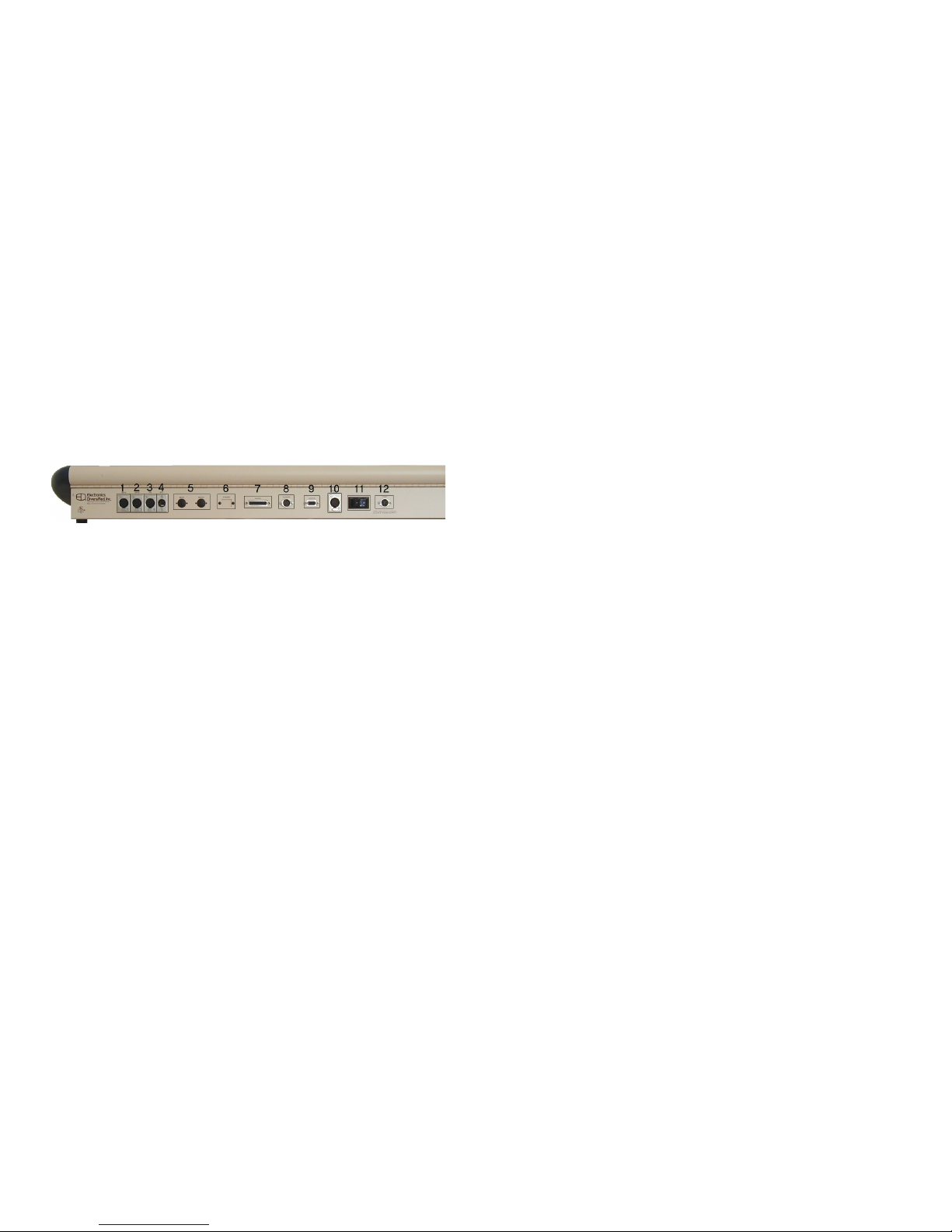
figure 2 Bijou Rear Panel
NOTES: Dust, smoke and liquids can ruin any piece of
quality electronics. Keep operation areas clean and do not
allow contamination of equipment. Do not operate this
console in a wet environment (the rain).
REAR PANEL OF THE CONTROL CONSOLE
REAR PANEL OF THE CONTROL CONSOLEREAR PANEL OF THE CONTROL CONSOLE
REAR PANEL OF THE CONTROL CONSOLE
Located on the rear of the console are the output and
input jacks, power jack and On/Off power switch. Refer to the
key below for an explanation of each item. Control cables
furnished with the console mate these outputs to the system
connection plates in your facility. There are three types of
connectors on the back of the Bijou; heavy-duty XLR
connectors, standard computer grade ‘D’ style connectors
and standard computer grade 5 pin DIN connectors. All XLR
connectors are keyed and locking. All DIN connectors are
keyed. Both XLR and DIN connectors should be rotated to
align the key prior to insertion. The ‘D’ connectors are locked
in place, after insertion, by tightening thumbscrews to insure
proper connection. All connectors should mate smoothly with
no undo force. DO NOT force connectors into position. As
many components use the same style of connector please
take the time to familiarize yourself with the location of each
connector prior to plugging in each device/accessory as this
will help to insure proper operation.
1. DMX OUTPUT
(Dimmers 1-512) (5-Pin XLR)
2. DMX OUTPUT
(Dimmers 513-1024) (5-Pin XLR)
3. HHR INPUT (Optional accessory)
(Hand Held Remote Control) (5-Pin XLR)
4. DMX INPUT
(5-Pin XLR)
5. MIDI IN & OUT (Optional accessory)
(5-Pin DIN)
6. ETHERNET OUTPUT (Optional)
IEEE 802.2/803.2 compliant UTP (RJ 45)
7. PRINTER OUTPUT
(DB25)
8. ALPHA NUMERIC KEYBOARD
(5-Pin DIN)
9. VGA/SVGA MONITOR OUTPUT
(D15, 3-row, VGA standard)
10. REMOTE VIDEO
(5-Pin XLR)
11. ON/OFF POWER SWITCH
12. POWER INPUT
(100-250v~, 50-60Hz, 0.7-0.3Amp)

8
ASSEMBLY
ASSEMBLYASSEMBLY
ASSEMBLY
Refer to REAR PANEL for location of appropriate jacks/plugs
for assembly prior to start.
To assemble the Bijou for operation:
First
FirstFirst
First (with the ‘On/Off’ switch in the off position) plug in the
Universal Power Pack/cord into the ‘Power Input’ jack on the
back of the Bijou. Next plug the parallel blade U-Ground end
into a ‘Surge protected’, outlet.
Like all microprocessor-based controls, the Bijou is sensitive
to power fluctuations on standard power lines. The console
should be plugged into an isolated circuit with a full equipment
ground and a UL approved surge suppresser. It is
recommended, that if a UPS (uninteruptable power supply)
was not part of the original purchase contract, that you
purchase one to protect the console (and your shows). A
UPS can be purchased from EDI or at your local computer or
office supply store.
DO NOT plug the console into the same outlet/circuit with
motors or SCR/TRIAC controlled devices.
Second
SecondSecond
Second, locate and plug the optional Alpha Numerickeyboard
into its jackon the backor the console.
(NOTE: The Bijou is designed to operate with any standard
PC/AT keyboard. The console can be shipped with a remote
keyboard as optional equipment. If you use a different
keyboard and you encounter problems please contact the
factory, as some manufacturers of AT after market keyboards
have been know to be incompatible.)
Third
ThirdThird
Third, following the manufacturer’s operations manual,
assemble your VGA/SVGA monitor. Plug in the parallel blade
U-Ground plug into a grounded outlet. Then plug the video
cable into the D15, 3 row, video standard plug on the back of
the control console. Locate the on/off switch on the monitor
and turn it to the on position.
Fourth
FourthFourth
Fourth, Locate your DMX cable, plug it into the 1-512 DMX
output jack of your console, then plug the other end of the
cord into a DMX input jack connected to your dimmers.
Fifth
FifthFifth
Fifth, go around to the front of the console and locate the
disk drive on the right end of the control console (when
viewed from an operator’s position). Push the eject button to
eject the plastic protector sheet that was placed in the drive
for transport. Insert any 3.5”, 1.44MB, high-density, PC
format disk into the disk drive.
(NOTE: Unformatted disks must be formatted prior to
recording show information to disk. If you have unformatted
disks they may be formatted on any standard PC.)
Sixth
SixthSixth
Sixth, reach over the top of the XY and AB cross faders to
the back of the control console. Find the On/Off switch and

9
Figure 3 Front Panel
push it to the ‘On’ position. This should light two blue LED’s
dotting the ‘I & J’ in the name Bijou on the front of the console
and the console should boot up with the “STAGE” screen on
the display ready for operation.
FRONT PANEL
FRONT PANELFRONT PANEL
FRONT PANEL
The Bijou is a microprocessor-based control system with
all operational instruction sets and control routines embedded
in read-only memory. The control console front panel allows
access to these instructions and routines through key
selections. All key selections are echoed on the system
command line located at the bottom left of your monitor.
The Bijou is available as a “Memory Operation” only
board or as a combination “Manual” (2 Scene/1 Scene) and
“Memory” board. If your board has 2 Scene/1 Scene
capabilities you will find two rows of sliders arranged in
groupings of 24, 48 or 72 to the left or above the XY cross
faders. Operation of this fader will be discussed in the
chapter on Manual Operation.
NOTE: In all discussions of operation key caps will be
represented in [ ] so the term [Stage] equals the control
console key with “Stage silk” screened on it.
On all configurations of the Bijou will find the following front
panel controls:
1. CROSS FADER SECTION
Location of XY and AB cross faders, [Load], [Fade Take],
[Go], [Stop/Rev], Grand Master Fader and Blackout
Switch.
2. CONTROL KEYS
Select active display screens for monitor. Access
channels and level information. Organize recording,
playback and editing sequences. Start and stop
automated features.
3. ENCODER WHEEL
Adjusts selected channel levels proportionally.
4. SUBMASTER/EFFECTS FADERS
Controls a manual and timed submaster & effect function
via fade handles or associated bump buttons.
5. DISK DRIVE (located on right side)
Off-line storage of recorded information.
On 2 Scene Preset versions of the Bijou you will find:
6. CHANNEL/FADERS (located on the left in two rows)
Used to set channel output levels in 2 Scene and 1 Scene
manual operation.
7. BUMP BUTTONS (located in a row below the
Channel/faders) Drive the associated Channel output
instantly to 100% when pressed returns to 0% when
released.
10
Figure 4 Screen Keys
CONTROL KEYS
CONTROL KEYSCONTROL KEYS
CONTROL KEYS
The primary access to the control system is through the
keypad controls on the front panel of the console. The
keypads are grouped together under common control
headings for ease of operation. There are four groups of
keys.
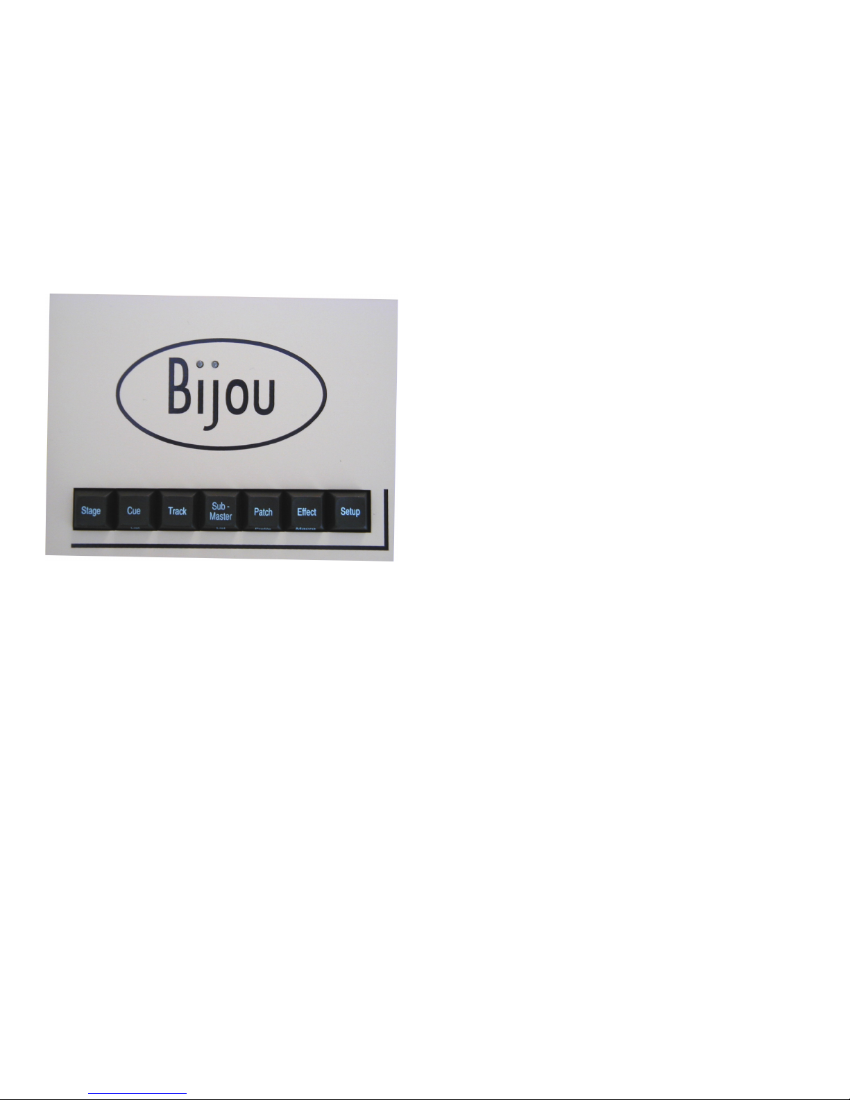
1. Screen Keys
2. Action Keys
3. Number Keys
4. XY & AB Fade Control Keys
SCREEN KEYS
SCREEN KEYSSCREEN KEYS
SCREEN KEYS
The Screen Keys access the primary displays of the
control console. The control console display screen can be
changed at any point by selecting a different Screen Key.
Changing screens does not affect of stop an action that was
set in place on a previous screen.
Note that several screen
keys access two screens, the primary screen is silk screened
on the top of the key and the secondary (second hit) screen is
silk screened on the front edge of the key cap.
STAGE [Stage]
Shows active output of control console. Shows channel
levels from all sources (except “Parked” channels) with
color-coding used to identify the source.
Shows active operation of Submasters & Effects.
Shows status of XY, AB, Grand Master faders and
Blackout switch.
Cues/Presets can be recorded or re-recorded and fade
times altered on this screen. Used as the primary screen
for running most shows.
CUE PREVIEW [Cue List] (first hit)
This is a preview screen that allows user to view and
modify cues/presets that are not presently active on
stage (blind recording). New cues/presets can be
created (blind) in this screen.
CUE LIST [Cue List] (second hit)
Displays operational information (#, Type, Times, Name)
for 27 cues, per page, and allows modification of their
times and attributes.
TRACK [Track]
This screen displays cues/presets and the related
channel level information in a spread sheet format.
Channel levels can be edited (blind) in this screen.
SUBMASTER PREVIEW [Submaster List] (first hit)
The Submaster Preview shows the attributes and
channel levels of individual submasters. A submaster’s
channel levels, times, and name can be created or
modified in this screen.
SUBMASTER LIST [Submaster List] (second hit)
Displays submasters in numerical order, by page, with
their associated name. Used to locate and identify
(quickly) specific submasters for use in hands on (live

11
Figure 5 Action Keys
action) operation.
PATCH [Patch Profile] (first hit)
This screen shows the system patch tables by dimmer.
Dimmers can be assigned to channels with proportional
levels and profiles. Dimmers may also be "Parked” at a
level, bypassing both the grand master and the black out
switch.
PROFILE [Patch Profile] (second hit)
The Profile screens list the default (1) profile, three
Preheat (2-4), a Square Law (5) and a Ballast profile (6)
as well as nineteen additional user modifiable profiles for
adjusting the turn on curve of individual dimmers.
EFFECT [Effect Macro] (first hit)
This screen is used to create effects and to assign
channels to steps at levels, set step time, select effect
type and give the effect a name.
MACRO [Effect Macro] (second hit)
This screen shows the keystrokes used to build each
macro. Macros can be created and edited in this screen.
SETUP [Setup]
These menu-accessed screens show all of the user-
definable system parameters and allow modification of
them. In addition they provide access to disk and print
functions. It is recommended that you spend time going
through each item in these screens to familiarize yourself
with them prior to starting to operate the console.
ACTION KEYS
ACTION KEYSACTION KEYS
ACTION KEYS
[Record]
First key used in a record sequence for recording
cues/presets and submasters.
[Update]
Automatically records levels that have been modified in
an existing cue.
[Delete]
Deletes Cues, Submasters, Effects, Macros
[Last]
Moves (in numerical order) to the last item in sequence,
such as; last Submaster, last dimmer, last channel etc.
[Next[
Moves (in numerical order) to the ‘next’ item in
sequence, such as; next Submaster, next Effect etc.
[Cue]
Accesses Cue memories.
[Sub-master]
Accesses Submaster memories.
[Effect]
Accesses Effect memories, used in assigning memories
to Submasters.

12
[Page Up]
Used to change position of display screen to see the last
major full screen block of information.
[Page Down]
Used to change position of display to see the next major
full screen block of information.
[FI], [F2], [F3]
The three ‘F’ (function) keys are “soft” keys. By this we
mean that their function changes for each screen.
Function keys are defined by their use in the lower right
corner of each individual screen, color code is magenta.
[Time]
Used in record process to assign fade time to cues, etc.
[Check]
Used in the STAGE and PATCH screens to do Channel
Check (Stage) and Dimmer Check (Patch).
[Create Macro]
Starts and stops the keystroke sequences for recording
a Macro.
[Macro #]
Used with a number of 1 to 2,500 and [ENTER] to
activate a macro.
[Thru]
Bridge key between channel selections and level setting
such as [2][5] [THRU] [3][2]
[Except]
Bridge key between channel selections and level setting
such as [2][5] [THRU] [3][2] [EXCEPT] [2][8]
[ ] Blank key caps
The two blank keys have no function under the latest
software. They are there for ‘future’ enhancements or
functions.
[And]
Bridge key between channel selections and level setting
such as [2][5] [THRU] [3][2] [AND] [9][8] [EXCEPT] [2][8]
[At]
Bridge key between channel selections and level setting
such as [2][5] [THRU] [3][2] [AND] [9][8] [EXCEPT] [2][8]
[AT] [FL]
[Cue Only]
In Tracking Mode of operation, levels are modified for
only the selected cue. The use of this key in the record
sequence resets the levels for the next cue as hard
levels without tracking.
[Clear]
Clears the entire command line that has been entered.

13
Figure 6 Number Keys
Figure 7 XY & AB Fader Control Keys
NUMBER KEYS
NUMBER KEYSNUMBER KEYS
NUMBER KEYS
NUMBER KEY PAD
Number keys are the primary way to enter values into
the Cues, Times, Submasters and Effects, Number Keys
are always reflected on the system Command Line
(lower left of screen).
NUMBER KEYS [1] thru [0]
Make a selection by entering the value on the Command
Line.
DECIMAL KEY [.]
Used to insert additional steps between whole number
cues or to identify tenth of seconds in timing operations.
FL Key [FL]
Also called FULL, assigns a value of 100% to a level in a
command sequence.
[Enter]
The final keystroke in most command line sequences.
Such as [2][5] [Thru] [3][2] [And] [9][8] [Except] [2][8] [At]
[FL] [Enter]
XY & AB FADER CONTROL KEYS
XY & AB FADER CONTROL KEYSXY & AB FADER CONTROL KEYS
XY & AB FADER CONTROL KEYS
The fader control keys are the primary way of
assigning control functions to the two sets of cross
faders for playback. Fader keys coordinate with the
Fader display on the Stage screen. Fader keys can
load, start, stop, reverse (backup) or take manual control
of a fade.
[Load]
Loads a cue stack on to the desired fader. Operates as
a (ready to fade into) or a “Go To” function (faded into
immediately) dependent on selections made in Setup
Screens.
[Fade Take]
Selects Manual or Automated actions with prerecorded
times for cues loaded to the cross faders.
[Stop/Rev]
Stops the fades in progress on the associated cross
fader. A second press will back up to the previous cue
prior to the [Go].
[Go]
Starts an automated fade loaded to the associated cross
faders.
SETUP SCREENS
SETUP SCREENSSETUP SCREENS
SETUP SCREENS
Before going on to explain operation of the Bijou please
take some time to go through all of options, settings and
functions of the Setup Screens.
14
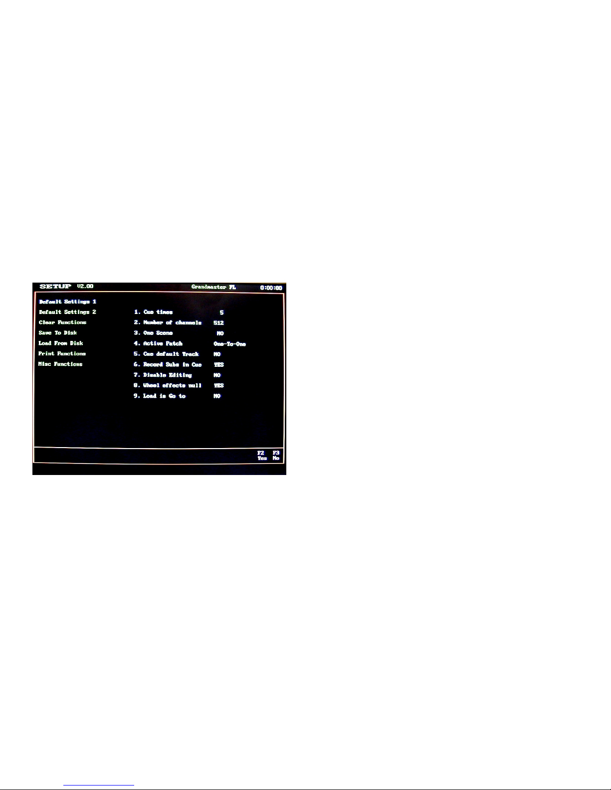
Figure 8 Default Setting 1 Screen
MAIN MENU
MAIN MENUMAIN MENU
MAIN MENU
The Setup Screen is divided into two columns. The left
column lists the topics that may be addressed and the right
column lists the items that may be modified, configured or
actions that can be taken under that topic.
By using the [Next] and [Last] keys you step thru the
seven setup topics. Note that as you step thru the column the
green headings will change to light blue indicating the active
category. And as you step thru the topics in the left column
note that the right side of the screen will change to show the
items available to be configured or addressed in the selected
category.
To select an item from the right column to modify or
address you simply enter the item number that will bring up
the available selections in the lower left of the screen in the
command line. Note that the [F1] and [F2] keys serve as YES
or NO commands for making changes requiring a yes or no
answer.
DEFAULT SETTING 1
DEFAULT SETTING 1DEFAULT SETTING 1
DEFAULT SETTING 1
1. Cue times
Sets a predetermined In and Out fade rate for cues as
they are being recorded. Used to speed up the cue
writing process as only variation from the standard
need to be entered in the record process. The default
time will be 5 seconds unless reset by you for your
show.
2. Number of channels
Best set to the maximum number of channels being
used in the system so processor does not create
confusion by showing more channels than your really
can use or waste processor memory or printer paper
looking at unused channels.
3. One Scene
Toggles between two scene preset and single scene
preset manual operation for those consoles with the
two-scene manual operation feature. To change use
[F1] or [F2] then hit the [Enter] key.
4. Active Patch
The Bijou can use one of three individual, dimmer to
channel, (assignments) patches. One-To-One is a
default where every dimmer in the system is controlled
by the channel of the same numeric placement at a
maximum output level of 100% (FL) and is using the
default Profile #1. Patch table 1 & 2 are user created
patch assignments (see section on creating a patch
page________). To select a patch for operation enter
[0] [Enter] for one-to-one or [1] [Enter] for patch 1 or [2]
[Enter] for patch 2.
5. Cue default Track
‘Yes’ places the default for all cues being recorded as
Tracking Cues. ‘No’ places the default for all cues
being recorded as Preset Cues.
(NOTE: In a
Tracking Cue when you create a cue and you do not
set a level for a channel and that channel had a level

15
Figure 9 Default Menu
Figure 10 Default Setting 2 Screen
in the previous cue the level for that channel will
“track” thru and into the cue you are creating. In a
Preset Cue only those channels with levels set will
have a level no matter what the previous cue had
recorded for the channels.)
6. Record Subs in Cue
A ‘Yes’ means that if a Submaster is active, it’s output
(live on stage) will be recorded as part of any cue or
submaster you record well in the stage screen. A ‘No’
means that you can use a submaster to have house
lights up low for rehearsal and some backstage work
lights on for painting scenery and not have those lights
record into cues that could ruin your show on opening
night.
7. Disable Editing
A ‘Yes’ means that someone can not accidentally
record over your cues, patch, subs, effects, disk etc.
without first coming to this screen and changing the
selection to “No”.
8. Wheel effects null
A null level means no level and is not the same as a
level of 0. If you select ‘Yes’ you will lock all selected
channels to the wheel even if they have a null level.
As you rotate the wheel (clockwise) to increase levels
all selected channels will increase output levels.
If you select ‘No’, any channel that you select that has
a null level will be ignored and remain at null output.
Only the selected channels that had an existing output
level of 0 or greater will increase when you move the
wheel.
9. Load is Go To
When “No” is chosen any cue selected by the [Load]
key will be loaded to the selected cross fader ready to
fade into in time when the [Go] key is pushed. The
sequence is [Load] [2] [Enter] which translates to: load
cue 2 enter. To go into the cue the operator then
pushes the [Go] key and the cue will operate
automatically.
When “Yes” is chosen the sequence is the same but
when you hit [Enter] the cue is instantly loaded to the
stage without the need to hit the [Go] key. If you want
to Go to a cue “In Time” you would follow the same
sequence with the insertion of the time. So for a go to
cue 2 in a 5 count the sequence would be: [Load] [2]
[Time] [5] [Enter]
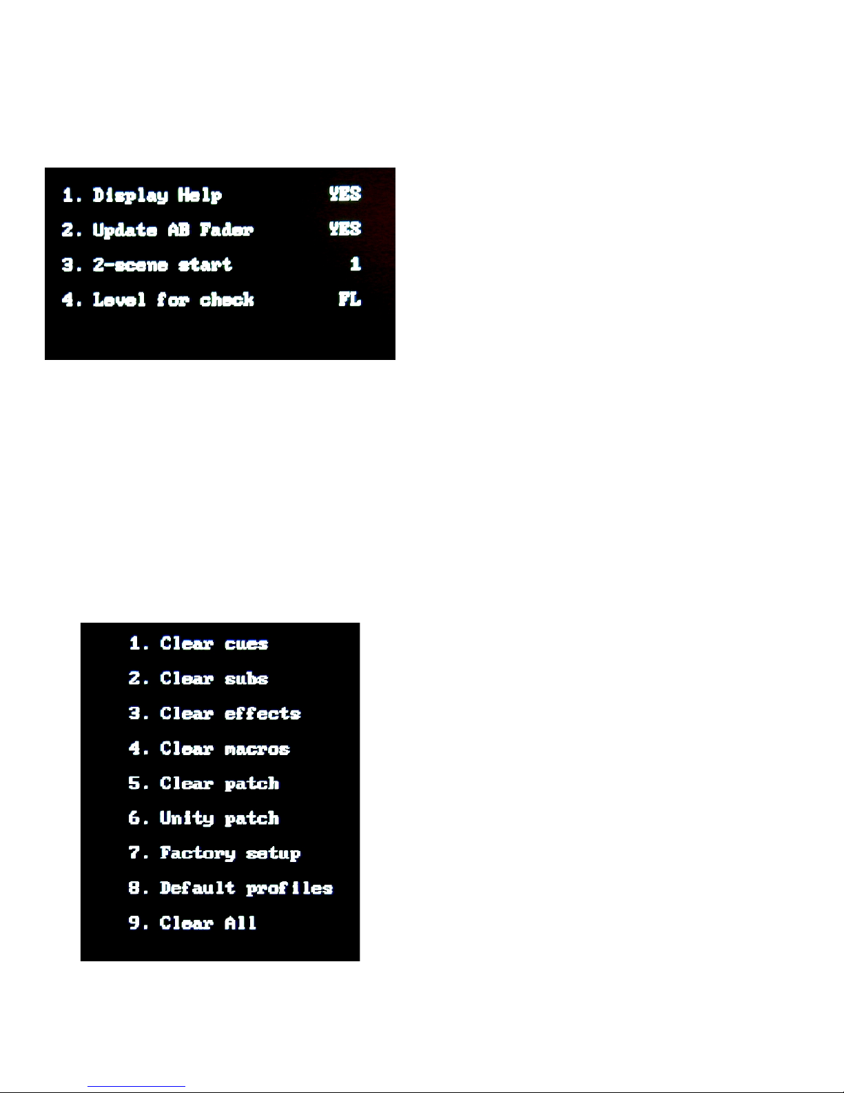
DEFAULT SETTING 2
DEFAULT SETTING 2DEFAULT SETTING 2
DEFAULT SETTING 2
1. Display Help
At the center of the Stage Screen below the Channel
Level section is a help window that will prompt you as
to which keys can be use in basic commands. After
you become proficient on the console this bright
section of the screen may be more distracting then it is
helpful. By selecting “No” you can remove the help
window from the stage screen.
16
Figure 11 Default Setting 2 menu
Figure 12 Clear Menu
2. Update AB Fader
A “Yes’ assumes that you are creating memory cues
and recording them on the AB cross faders. And that
you want to use the [Update] key to confirm and store
any modifications that you make to an existing cue.
This would be the normal mode of operation if you plan
to use the board in either 2 scene or 1 scene manual
operation simultaneously with memory mode
operation.
If you have the memory operation only version of the
Bijou or if you are operating in memory mode only and
wish to work on cue building primarily on the XY fader
then you will want to select “No” which will make the
[Update] key active on the XY fader and not on the AB.
NOTE: to prevent accidental modification of the wrong
preset the [UPDATE] can not be active on both cross
fader cue stacks at the same time.
3. 2-scene start
Bijou consoles that are configured for 2 scene and 1
scene manual operation have channel faders with silk-
screened labels starting at 1 and going up numerically.
In some instances you may wish to use this section of
the board to control channels higher then the numbers
silk screened on the console. To do so set the
number of the channel number that you want fader 1
to address and the rest of the faders will automatically
fall in line sequentially. So if you want Slider 1 to
control Channel 97 from the Default Settings 2 menu
you would push [3] [9] [7] [Enter]. To change it back to
slider 1 = channel 1 push [3] [1] [Enter].
4. Level for check:
This allows you to set a maximum output level for
doing a dimmer or channel check using the [Check]
and [Next] [Last] keys in the STAGE or PATCH
screens. Some Master Electricians like to leave this
level at full thinking that if they are going to blow out a
lamp filament the pre show check is the time to do it
rather then in the middle of the show. And if you hit a
weak, cold, lamp filament with a full instant on it will
often do just that. Other ME’s feel that doing this to
the lamps shortens the lamp life of all of the lamps.
So the will set a maximum output level for check that
does not go to full on, say 80%. Some do a dimmer
check and some do a channel check any of these
options is valid. EDI will let you make the choice that
makes sense to you.
CLEAR FUNTIONS
CLEAR FUNTIONSCLEAR FUNTIONS
CLEAR FUNTIONS
The Clear Functions allow you to selectively clear items
from the system memory one at a time, or, by accessing Item
#9, all memory can be cleared. The Clear Functions also
allows you to easily restore the system to the original factory
default setting by selecting [7] [Enter] and after the promote of
‘Are You Sure’ in the command line hitting [Enter] again to
confirm.
1-5.Clears specific memory sections.
17
Figure 13 Save Menu
Figure 14 Load Menu
7. Restores original factory default settings without
clearing Cues, Effects, Submasters etc.
8. Restores all 25 dimmer Profiles to the original default
settings.
9. Clears all user-recorded information from the system
memory.
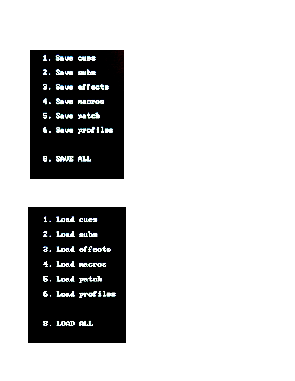
SAVE TO DISK
SAVE TO DISKSAVE TO DISK
SAVE TO DISK
The Save to Disk menu is used to transfer any recorded
information from the console to the disk for off-line storage.
This menu allows the individual items listed to be transferred,
one at a time, to the disk, or, by selecting Item 8, all memory
can be saved to the disk at the same time. The Bijou uses
only 3.5” 2HD floppy disks formatted for IBM compatible PC’s.
If you need to format a disk you can do that on your PC.
1-6. Save To Disk functions allows you to save specific
portions of recorded memory.
8. Allows you to save all user recorded information to
the disk. This provides a backup of your show that you
may need in the event that someone else uses the board
and over writes the board memory.
LOAD FROM DISK
LOAD FROM DISKLOAD FROM DISK
LOAD FROM DISK
The Load From Disk menu is used to transfer
prerecorded information from the disk to the memory of the
control console. This menu allows the individual items listed
to be transferred, one at a time, or, by selecting item #8, all
can be loaded at the same time. Loading information from
the disk to the console memory will overwrite any existing
information.
1-6.Load From Disk functions allows you to selectively
load specific portions of memory from disk to console
memory.
8. Loads all from disk over writing console memory.
NOTE: A disk may be “Write Protected” to prevent alteration
of stored data. To write protect a disk, orient the diskette so
that the round metal circle is pointed toward you. Push the
write-protect tab, located in the lower right-hand corner, down
to open the slot. When this slot is open the disk is protected
and no new data can be recorded. A “Write Protected” disk
will cause a “Unformatted Disk” error message to appear
when attempting to record information to disk.
Diskettes are sensitive to magnetic fields, which may erase or
corrupt recorded information. Keep diskettes away from
magnetic field such as Speakers, Telephone Bells/Ringers,
Motors, Transformers and Power supplies (i.e.; Little Lights),
dimmers, etc.
18
Figure 14 Print Menu
Figure 15 MISC Menu
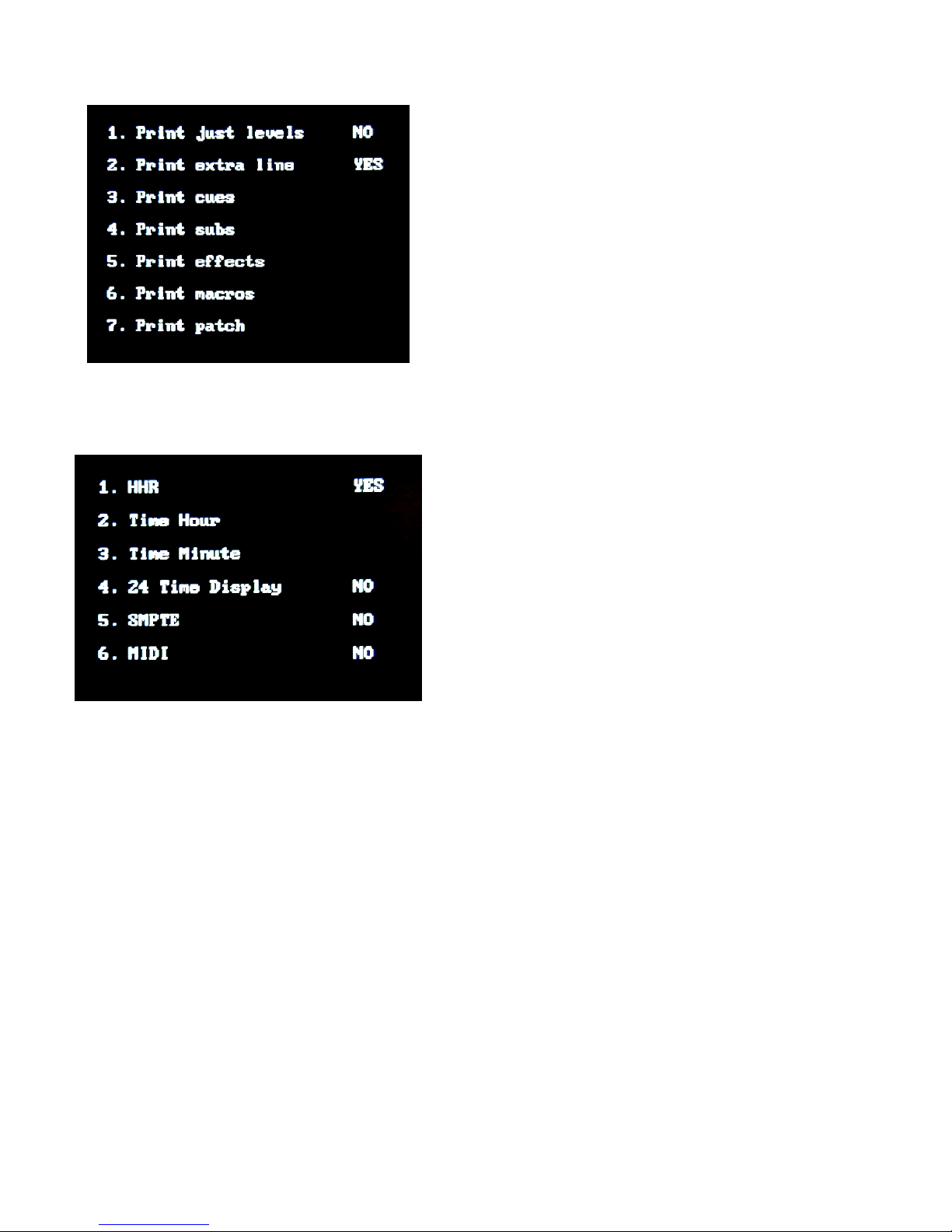
PRINT FUNCTIONS
PRINT FUNCTIONSPRINT FUNCTIONS
PRINT FUNCTIONS
The Print Functions menu allows access to all print
features. Item:
1. Allows you to print only the channel output levels for
each cue.
2. Print extra line. Some printers require this command
to advance the paper at the end of each line of print.
Use YES command if your printer is over printing and
not advancing.
3 - 7. Prints all information for; cues, subs, effects,
macros and patch.
NOTE: For compatible printers and printer set up go to the
ACCESSORY section at the end of this manual.
MISC FUNCTIONS
MISC FUNCTIONSMISC FUNCTIONS
MISC FUNCTIONS
The Miscellaneous Functions menu allows you to
activate or deactivate optional accessories and to reset the
console clock (it is easier then on your VCR) functions.
1. HHR
Hand Held Remote. If you purchased a system with the
optional Hand Held Remote then this position should be
toggled [F2] to show YES. If your system does not
have this option toggle [F3] to NO.
2. Time Hour
Allows you to set the hour on the system clock (upper
right hand corner of all screens). To set the time hit [2]
Time Hour [_#_] the hour of the day [Enter]. For 9
o’clock the entry would be [2] [9] [Enter] for 11 o’clock
the entry would be [2] [1] [1] [Enter].
3. Time Minute
Allows you to set the minute on the system clock. To
set the minutes hit [3] Time Minutes [_#_] the minutes,
then enter.
4. 24 Time Display
Allows the clock to display time in “Military/International”
time. If you use this selection 5:30 PM will be displayed
as 17:30:00 instead of 5:30:00. This needs to be
selected if using SMPTE or MIDI Show Control
Functions that are AM and PM dependent. Select 24
hour display before setting hour in 2 above.
5. SMPTE
This function is an option that may not have been
purchased with your console. SMPTE stands for the
Society Of Motion Picture & Television Engineers time
code system. A YES in this item activates input/output
port and screen for programming SMPTE timed events.
6. MIDI
This function is an option that may not have been
purchased with your console. A YES in this column

19
Figure 16 Bijou disk drive
activates input/output port and screen for programming
MIDI activated events.
If the clock is not set to the proper time you should set it
at this time. The time will stay accurate even with the power
turned off as the board has a battery backup built in to protect
memory loss.
SECTION II: BIJOU OPERATIONS the fun
SECTION II: BIJOU OPERATIONS the funSECTION II: BIJOU OPERATIONS the fun
SECTION II: BIJOU OPERATIONS the fun
stuff.
stuff.stuff.
stuff.
O.K. we are going to actually start operating the machine
rather than just looking at it. But as we have no way of
knowing if you just got the console from the factory or, it has
been in use for years and you are just a new user, please do
the following in order for you to follow along with the
discussion.
Turn on the console and the VGA/SVGA display screen.
The system will boot up to the STAGE screen.
1. If you have a Bijou that has 2 scene-preset faders on
the left move them all down to ‘0’.
2. Move the XY and AB Faders down to the [Stop/Rev]
key. Move the Grand Master down to ‘0’. Note that at
the top of all screens there is the word Grandmaster in
green with an output level shown in white (if there is an
output) and red if the Grandmaster is turned to 0 or off.
3. Turn the Blackout switch to the ‘Off’ position. Note that
when you turn the Blackout switch to Off a red LED
lights above the switch and the word BLACK OUT
appears at the top center of all screens in RED.
4. Move all Submasters/Effects sliders down to 0.
PROTECTING PRE-RECORDED SHOW INFORMATION
PROTECTING PRE-RECORDED SHOW INFORMATIONPROTECTING PRE-RECORDED SHOW INFORMATION
PROTECTING PRE-RECORDED SHOW INFORMATION
5. Locate the disk drive on the far right end of the console.
Eject the disk if there is one in the machine. Mark the
date and time you ejected the disk so if there was a
show recorded on it you can not be blamed for messing
it up.
6. Find two new unused 3.5” High Density PC formatted
disks. Insert one of the disks into the disk drive.
7. From the Save To Disk screen enter [8] SAVE ALL
[Enter].
When everything is saved, eject the disk and write the
date and time on it. This is a new, true copy of the board
settings as you found it and may be more accurate than the
disk you ejected back in step 5.
8. Now mark your name and date on the last NEW disk
and insert it in the disk drive.
9. Using the [Last] key go to Clear Functions, hit [9] Clear
All [Enter]. This will remove any prerecorded show
20
Figure 17 Patch Screen
information from the system and allow you to start
operating the machine with a clean slate.
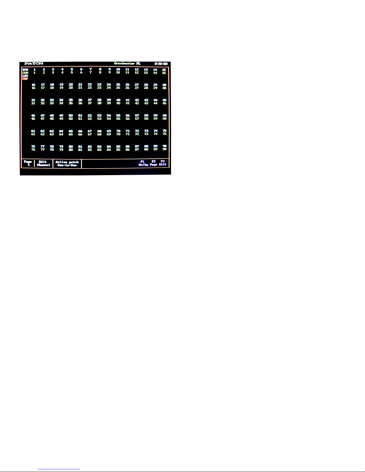
PATCH (screen)
PATCH (screen)PATCH (screen)
PATCH (screen)
To begin you need to understand what a patch is. In a
lighting system you will have many lighting fixtures that you
“plug” into dimmer circuits. You may have several light
fixtures “plugged” into a single dimmer circuit because they
are being used together and do not need individual control.
Often many fixtures on many dimmers are doing the same
thing and you would like to have all of them controlled
together. An example of this would be the many dimmers
that control the auditorium house lights. In many cases it
would be nice to control all of the house lights on one
Channel/fader. To do this, dimmers are Patched (plugged
into) to a Channel/fader via the patch screen. Although the
PATCH screen lists DMR (dimmers) this is a DMX control
address and in addition to dimmers can be used to control
any device that uses USITT DMX512 control protocol for its
operation. This could include items like; color scrollers,
moving lights, fog machines, relay panels, etc.
To get to the PATCH screen you need to push the
[Patch Profile] key once. The PATCH screen will appear on
your display. The Bijou has two patch tables that can be
modified by the user and one default (One-To-One) patch
that can not be modified. The patch allows you to assign one
or more dimmers to a channel. You can also set a maximum
output level for a dimmer. And you can assign a fade in
curve (Profile, see next section) for each dimmer. In addition
dimmers can be ‘Parked’ or changed to Non-Dim units in this
screen.
To select PATCH Page 1 or PATCH Page 2 for modification
use the [F2] key followed by a [1] [Enter] or a [2] [Enter].
NOTE: neither patch will be in use by the board until you go
to setup and make it the “Active Patch”. To do that you would
need to hit [Setup] Default Settings 1 [4] Active Patch [0] One-
To-One or [1] PATCH Page 1 or [2] PATCH Page 2 then
[Enter] to confirm the active patch. If you are just learning the
system leave the default One-To-One patch as the active
patch for now.
On the Patch screen you will see ninety dimmers listed
at a time, with DMR 1 - 90 shown on the first screen. DMR
(dimmers) are shown as blue #’s. Using the [Page Up] and
[Page Down] keys will let you see up to 1024 dimmers.
NOTE: The number of dimmers and DMX devices in your
system will limit the number of dimmers you will need to
patch.
PATCH AT LEVEL
PATCH AT LEVELPATCH AT LEVEL
PATCH AT LEVEL
DMR (dimmers) are assigned to CHN (Channels/faders
shown as green #’s) using the [At] [Thru] [And] [Except] [At]
and [Enter] keys. To make CHN 1 control DMR 3 you would
hit; [3] [At] [1] [Enter]. This puts the control of dimmer 3 onto
channel 1 with an output of 100% and Profile 1. As the most
common output level for dimmers is 100%, the LEV (white)
row is left blank unless you input a level other than 100%.
This manual suits for next models
1
Table of contents
Other Electronics Diversified Lighting Equipment manuals


Popular Lighting Equipment manuals by other brands


ROADWORX
ROADWORX Lighting Stand 1 user manual

Federal Signal Corporation
Federal Signal Corporation VISTA 581016-OHP Series Installation and maintenance instructions

Welch Allyn
Welch Allyn ProXenon 350 manual

MCI Light
MCI Light BOW installation instructions

Perel
Perel WTL6 user manual

LIGMAN
LIGMAN ZAAB 2 installation manual