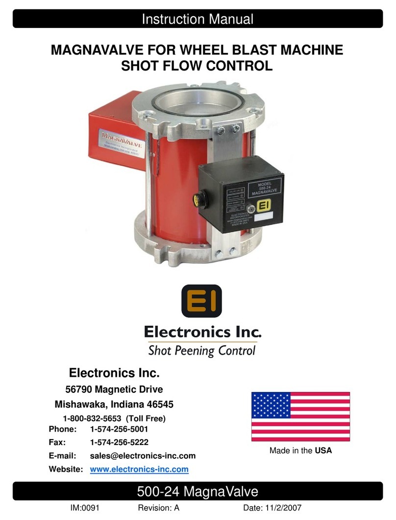
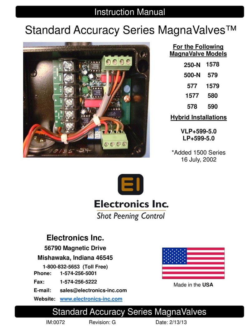
Electronics MagnaValve WM 3000-24 User manual

2
Table of Contents
Product Overview and Principle of Operation........................................................................... 3
Installation.................................................................................................................................................. 4
Adjustments ..............................................................................................................................................4
Operation - MagnaValve...................................................................................................................... 4
Operation - Remote Valve Driver .....................................................................................................5
Specifications ............................................................................................................................................6
Dimensions ................................................................................................................................................7
Remote Valve Drive Cable Connection ......................................................................................... 8
AC-24 Controller Cable Connection ............................................................................................... 8
Troubleshooting ......................................................................................................................................9
Maintenance............................................................................................................................................10
Spare Parts List........................................................................................................................................10
Contacting Electronics Inc.................................................................................................................10
Limited Warranty...................................................................................................................................11
Read this manual completely before installing the MagnaValve.
WARNING!
The MagnaValve emits magnetic elds and can be harmful to pacemaker wearers.

3
Product Overview and
Principle of Operation
MagnaValve® Description
The MagnaValve® WM 3000-24 is a normally closed valve that regulates the ow
of steel shot or grit in wheel-blast machines for blast cleaning applications. It is a
powerful valve with a ow rate capacity of up to 3,000 lb/min (1,361 kg/min) for
wheels up to 125 hp. The Remote Valve Driver for the MagnaValve comes with a 6-ft
cable for installation in the customer’s electrical panel, making it an ideal valve for
blast machines in high-temperature environments.
The MagnaValve reduces media usage, energy costs, machine downtime, and wear
and tear on equipment.
How It Works
The MagnaValve’s maintenance-free construction includes a rare earth permanent
magnet for normally closed operation and an electromagnet for controlling shot ow
rates. With power applied, the magnetic eld is neutralized and shot is allowed to
ow through the valve.When no power is applied to the MagnaValve, the permanent
magnet stops all ow. If the power is interrupted for any reason, the permanent
magnet securely holds the shot.
The MagnaValve is factory tested and results are supplied upon request.
MagnaValve Controllers for Closed-Loop Operation
For an “automatic” closed-loop operation, an Electronics Inc. AC-24 Controller will
detect the current load on the wheel motor and regulate the ow of media to the
WM 3000-24. The WM 3000-24 MagnaValve, with the AC-24 Controller, provides
reliable, repetitive, and consistent media ow rates for blast cleaning applications.
The MagnaValve system makes it easy to document ow rates and establish or repeat
a good set-up.
AC-24 Controller Data Sheet
http://www.electronics-inc.com/uploads/AC-24Controller(1).pdf
AC-24 Controller Instruction Manual
http://www.electronics-inc.com/data_sheets_and_instruction_manuals_for_wheel_blast_machine_products2.html

4
Installation
MagnaValve
The MagnaValve must be mounted in a vertical position with an adequate supply of
media above it.
Remote Valve Driver
The Remote Valve Driver should be mounted in an electrical panel that conforms to
the temperature range of 50˚- 120˚ F (10˚- 49˚ C).
Adjustments
MagnaValve
No adjustments are required or recommended. The valve has been tested at the
factory prior to shipment.
Remote Valve Driver
Adjustments to the Remote Valve Driver can be made from the front of the driver;
however, the factory settings should not be changed.The output signal is 10 Vdc. See
page 5 for additional information on the Remote Valve Driver.
Operation
MagnaValve
Signals used to operate the MagnaValve originate at the AC-24 Controller. There are
three conditions necessary for correct operation.
1) Power. 24 Vdc power must be continuously applied to the valve. The valve
requires 2 Amps for operation and a power supply rated at 50 Va. The voltage
should be 24 ±2 Vdc.
2) Enable Signal. The 24 Vdc Enable Signal is used to activate the valve.
3) Input Signal. The analog 0-10 Vdc input signal must be above 0.25 Vdc as a
minimum ow command signal.
AC-24 Controller Operation
Please download the AC-24 Instruction Manual
http://www.electronics-inc.com/data_sheets_and_instruction_manuals_for_wheel_blast_machine_products2.html

5
830500830500
Valve Pulse
▼
620 Hz
Program Port Test Connector
0-10 V IN
NA
NA
24 V
Pulse Hz
GND
Valve On
Vin > 0.25 Vdc
Enable (24 Vdc)
Power (24 Vdc)
è
ç
é
Valve Pulse
Rate at which the valve dispenses shot. The Valve Pulse
is factory set to match the best ow characteristics of
the media (cast steel or cut wire). The typical operation
rate is 8 Hertz.
Test Connector
Provides access to
diagnostic voltages.
• 0 - 10 Vdc input
• 24 Vdc “Enable” input
• 6 - 20 Hertz pulse rate
• 0 Vdc common
Operation
Remote Valve Driver
Valve Driver Panel (behind the cover plate)
*Diagnostic LEDs
Valve On. Indicates when power is being sent to the MagnaValve’s electromagnet. When the
LED is on, the valve is on for full capacity ow rate. When the LED is o, the MagnaValve’s
permanent magnet has stopped the media ow. When the LED is blinking, the shot ow is
being regulated.
Vin > 0.25 Vdc. Indicates that an analog signal input greater than 0.25 Vdc has been received.
When this LED is o, no media ow is allowed. The input signal range is 0 -10 Vdc. At 10 Vdc,
the MagnaValve will open to full capacity. The relationship between the 0 -10 Vdc input signal
and actual ow rate is non-linear.
24 Vdc Enable. Indicates that the 24 Vdc Enable Signal has been received. When the LED is
o, the MagnaValve is inhibited and no shot will ow. This feature is provided as an on-o
action so the 0-10 Vdc input signal does not have to be disabled or removed.
24 Vdc Power. Indicates that 24 Vdc is available to operate the electromagnet for media ow.
It should always be available and able to supply 2 Amps.
All four LEDs must be on in order to have media ow.
Diagnostic LEDs*
The large knurled screw on the front cover of the Remote Valve Driver can be removed to gain
access to the factory adjustments. Please refer all adjustments to qualied personnel.

6
Specifcations
MagnaValve
Power +24 Vdc @ 2A (50 VA)
Media Steel Shot and Grit
Weight 32 lb (14.5 kg)
Mode Normally Closed
Temperature Range Valve: 50˚- 230˚ F (10˚-110˚ C)
Signal Input 0 - 10 Vdc
Flow Output 0 - 3,000 lb/min (0 - 1,361 kg/min)*
Display LEDs Valve On
0 - 10 Vdc Command Input Available
24 V Flow Enable
+24 Vdc Power
Cable: 2 Conductor shielded 18 AWG or equivalent.
Connect shield at control only.
* Flow rate based on S230 cast steel shot
Remote Valve Driver
Temperature Range 50˚- 120˚ F (10˚- 49˚ C)

7
Dimensions
.91”
(23 mm)
9.30”
(236 mm)
4.50”
(114 mm)
1.50”
(38 mm)
1.50”
(38 mm)
.56”
(14 mm)
10.00”
(254 mm)
9.00”
(229 mm)
2.87”
(73 mm)
4.29”
(109 mm)
7.13”
(181 mm)
5.00”
(127 mm)
ValveOn
MagnaValve®
For stability, the MagnaValve should be located as close as possible (within at least 3 ft / 1 m) to the blast machine wheel.
Panel spacing for the Remote Valve Driver: 5” on cable side, 0.5”on top and bottom.
5.460” (138.7 mm)
4.890” (124.2 mm)
6.62”
(168.1 mm)
4.739”
(120.4 mm)
2.032”
(51.6 mm)
.886”
(22.5 mm)
3.772”
(95.8 mm)

8
Maximum
Temperature:
212˚ F / 100˚ C
Place valve within
3 ft/1 m of wheel
feedspout media
inlet
Cable #1
White
Green 24 Vdc
0 Vdc
Enable Input
24 Vdc Enable Output 24 Vdc
Flow Command
Input 0 -10 Vdc Flow Command
Output 0 - 10 Vdc
Blue
Orange
Cable #2
Red
Black
Maximum
Temperature:
100˚ F / 37˚ C
Place driver module in
electrical control panel
24 Vdc
0 Vdc
Signal
Ground
Earth
Customer
Power
Supply
Shunt
0.05 Ω
Remote Setpoint
(if used) 0 - 10 Vdc
Recorder output
(if used) 0 - 10 Vdc
Remote Enable
(if used) 24 Vdc
Customer’s
100:5 Current Transformer
Pass one loop through
center 0-100 Amps
current transformer
Cable #1- A six-foot
cable and plug are
supplied with the
MagnaValve and only
the green and white
wires need to be
connected. Do not use
the other wires in the
cable. Wiring from
the MagnaValve to the
Remote Valve Driver
should be in a private
conduit (no adjacent
motor leads, etc).
Use 16 AWG. For runs
longer than 98 ft/30 m,
use larger wire such as
14 AWG.
4
8
20
19
2
18
9
5
7
WM 3000-24
REMOTE
VALVE DRIVER
AC-24 CONTROLLER
Cable #2 - A six-foot
cable and plug are
supplied for Cable #2.
Do not use green and
white wires. Connect
red (+) and black (–)
wires directly to 24 Vdc
power source. Connect
blue and orange to
AC-24 Controller
terminals 9 and 8.
(+)
(-)
▼ ▼
▼
1
3
1
3
5
2
6
4
Note #1
Note #2
Note #1 Do not attach Red and Black wires to
terminals 19 and 20. Connect Red and Black
wires directly to power supply — this prevents
ground noise interference.
Note #2 Shunt is supplied with AC-24 Controller
and is attached to terminals 5 and 7.
AC-24 Controller Cable Connection
Remote Valve Driver Cable Connection
The Remote Valve Driver should be installed in customer’s electrical panel. The 6-pin plug and cable wires connect
to customer’s wiring per the following:
White MagnaValve power signal - connect to valve driver, White only
Green MagnaValve power signal - connect to valve driver, Green only
Red Customer Power Supply in control panel - Power bus hot +24 Vdc
Black Customer Power Supply in control panel - Power bus common 0 Vdc
Blue 24 Vdc Enable Input - connect to AC-24 Controller Screw terminal #9, Enable Output
Orange 0-10 Vdc Flow Command Input - connect to AC-24 Controller Screw terminal #8, Flow Command Output

9
Troubleshooting
If all of the LEDs are on but there is no media ow, please check the following:
1) Is the mechanical slide gate valve above the MagnaValve fully open?
2) Is media available from the hopper?
3) Is there a blockage above or below the MagnaValve?
4) Is the magnetic eld completely cancelled when the “Valve On” LED is on? Check this by
removing the valve from the machine and applying the proper signals for 100% ow. Did all
of the shot fall from the valve?
If the problem can’t be identied or if you detect a problem with the magnetic eld,
contact Electronics Inc. Please have the following information ready.
1) Number of valves on the machine ___________________________________
2) Controller model _________________________________________________
3) Valve model____________________Valve serial number_________________
4) Media type ocast steel ocut wire ogrit oother___________________
5) Media size ______________________________________________________
6) Wheel size (hp)_______________ Wheel size (diameter) _________________
7) Desired wheel amperage (Amps) ____________________________________
8) Wheel speed (cpm) _______________________________________________
9) Blasting cycle time________________________________________________
10) Time between cycles ______________________________________________
Make note of LED indicators on the MagnaValve:
How do the MagnaValve LED indicators react during the blast cycle?
__________________________________________________________________________
Make note of LED indicators on the AC-24 Controller (if used):
How do the AC-24 Controller LED indicators react during the blast cycle?
__________________________________________________________________________
What does the AC-24 Controller display at the end of the blast cycle? _____________________
To expedite a solution, please send images of your valve installation,
the valve’s ID label and/or a video of the controller and valve driver during operation.
Troubleshooting with Skype is also recommended.
Electronics Inc.
Telephone: (574) 256-5001 or 1-800-832-5653 (USA and Canada)
Fax: (574) 256-5222

10
Maintenance
The MagnaValve has no moving parts and is thereby maintenance free.
Spare Parts List
The MagnaValve has no moving parts to replace.
Contacting Electronics Inc.
Electronics Inc.
56790 Magnetic Drive
Mishawaka, Indiana 46545 USA
Telephone: (574) 256-5001 or 1-800-832-5653 (USA and Canada)
Fax: (574) 256-5222
Email: [email protected]
Website: www.electronics-inc.com
Electronics Inc. makes no representations or warranties, either expressed
or implied, with respect to the contents of this publication or the products
that it describes, and specically disclaims any implied warranties of
merchantability or tness for any particular purpose. Electronics Inc. reserves
the right to revise this publication and to make changes and improvements to
the products described in this publication without the obligation of Electronics
Inc. to notify any person or organization of such revisions,
changes or improvements.

11
Limited Warranty
The warranty obligations of Electronics Inc. for this product are limited to the terms set forth
below.
Length of Warranty Period
This limited warranty lasts one (1) year from the shipping date of this product.
What is Covered
This limited warranty covers defects in materials and workmanship in this product.
What is Not Covered
This limited warranty does not cover any damage, deterioration or malfunction resulting from
any alteration, modication, improper or unreasonable use or maintenance or use of a media for
which the MagnaValve was not calibrated, misuse, abuse, accident, neglect, exposure to excess
moisture, re, improper packing and shipping (such claims must be presented to the carrier),
lightning, power surges, or other acts of nature.This limited warranty does not cover any damage,
deterioration or malfunction resulting from the installation or removal of this product from any
installation, any unauthorized tampering with this product, any repairs attempted by anyone
unauthorized by Electronics Inc. to make such repairs, or any other cause which does not relate
directly to a defect in materials and/or workmanship of this product. This limited warranty does
not cover equipment enclosures, cables or accessories used in conjunction with this product.
How to Obtain a Remedy Under this Limited Warranty
To obtain a remedy under this limited warranty, contact Electronics Incorporated by letter, email,
fax or telephone with the following information:
• Product name and model
• Product serial number
• Original shipping date (see label on product)
• Company name and location
• Name of contact person for description of symptoms
• Return shipping address and any special instructions
If it is determined that the product must be returned under this limited warranty, a Returned
Goods (RG) number, obtained from Electronics Inc., will be required. This product should be
properly packed to prevent damage in transit. Cartons not bearing a RG number will require
additional processing time and repair service may be delayed.
What Electronics Inc. Will Do Under This Limited Warranty
Electronics Inc. will, at its sole discretion, provide one of the following remedies to whatever
extent it shall deem necessary to satisfy a proper claim under this limited warranty:
1.) Elect to repair or facilitate the repair of any defective parts within a reasonable period of time,
free of any charge for the necessary parts and labor to complete the repair and restore this
product to its proper operating condition. Electronics Inc. will pay the shipping costs necessary
to return this product once the repair is complete.
2.) If the defective product cannot be repaired, it will be replaced with a new unit and the original
warranty period will be extended by six (6) months. Electronics Inc. will pay the shipping costs
necessary to replace this product.

12
If this product is returned to Electronics Inc., the product must be insured during shipment, with
the insurance and shipping charges prepaid. If this product is returned uninsured, Electronics
Inc. does not assume any risk of loss or damage during shipment. Electronics Inc. will not be
responsible for any costs related to the removal or re-installation of this product.
Out-of-Warranty Product
Product that is out-of-warranty will be repaired at customer’s request and the cost of repair will be
disclosed prior to proceeding with the repair. A purchase order must be received prior to repair. If
the product cannot be repaired, Electronics Inc. will provide one of the following remedies:
1) New unit at current pricing with a one (1) year Limited Warranty from the shipping date of
product.
2) Refurbished unit (if available) at a discounted price with a six (6) month Limited Warranty from
the shipping date of product.
Limitation on Liability
The maximum liability of Electronics Inc. under this limited warranty shall not exceed the actual
purchase price paid for the product. Electronics Inc. is not responsible for direct, special, incidental
or consequential damages resulting from any breach of warranty or condition, or under any other
legal theory to the maximum extent permitted by law.
Exclusive Remedy
To the maximum extent permitted by law, this limited warranty and the remedies set forth above
are exclusive and in lieu of all other warranties, remedies and conditions, whether oral or written,
express or implied.To the maximum extent permitted by law, Electronics Inc. specically disclaims
any and all implied warranties, including, without limitation, warranties of merchantability and
tness for a particular purpose. If Electronics Inc. cannot lawfully disclaim or exclude implied
warranties under applicable law, then all implied warranties covering this product, including
warranties of merchantability and tness for a particular purpose, shall apply to this product as
provided under applicable law.
Rights Under State Law
This warranty denes specic legal rights relative to these products provided by Electronics Inc.
Legal rights may also vary from state to state.
Table of contents
Other Electronics Control Unit manuals
Popular Control Unit manuals by other brands
Miele professional
Miele professional A 304 operating instructions

Hunter
Hunter I-40 manual
National Instruments
National Instruments NI USB-9264 USER GUIDE AND SPECIFICATIONS
eks
eks d-light DL-485MBP Description and manual
Veethree
Veethree VeeCAN 320 instructions
PAW
PAW SolarBloC mega Installation and operation instruction

