Electrostatic Technology FlexiCoat 300 User manual

Electrostatic Technology, Inc FlexiCoat® Model 300 Coater
Serial #20158 i
TABLE OF CONTENTS
1 INTRODUCTION................................................................................................................................................. 1
2 SHIPPING ............................................................................................................................................................. 1
3 OPERATING PRINCIPLES ............................................................................................................................... 2
3.1 SCHEMATIC DIAGRAM OF AN ELECTROSTATIC COATER .................................................................. 2
3.2 PROCESS DESCRIPTION................................................................................................................................ 2
4 GENERAL SAFETY ............................................................................................................................................ 3
4.1 INTRODUCTION.............................................................................................................................................. 3
4.2 SAFETY SYMBOLS......................................................................................................................................... 4
4.3 QUALIFIED PERSONAL................................................................................................................................. 4
4.4 INTENDED USE ............................................................................................................................................... 5
4.5 INSTALLATION............................................................................................................................................... 5
4.6 OPERATION ..................................................................................................................................................... 6
4.7 LESS OBVIOUS DANGERS............................................................................................................................ 8
4.8 ACTION IN THE EVENT OF A SYSTEM OR COMPONENT MALFUNCTION........................................ 8
4.9 MAINTENANCE & REPAIR ........................................................................................................................... 9
4.10 DISPOSAL.................................................................................................................................................. 10
5 AIR AND ELECTRICAL REQUIREMENTS ................................................................................................ 11
5.1 FLEXICOAT®.................................................................................................................................................. 11
5.1.1 Air ........................................................................................................................................................... 11
5.1.2 Electrical ................................................................................................................................................ 11
6 DESCRIPTION OF COMPONENTS............................................................................................................... 12
6.1 FLEXICOAT®300 COATING STATION...................................................................................................... 12
6.1.1 Tooling Plate .......................................................................................................................................... 12
6.1.1.1 Low Velocity Plume (cover)................................................................................................................................12
6.1.2 Powder Level Sensor .............................................................................................................................. 12
6.1.3 Powder Feed Chamber........................................................................................................................... 13
6.1.4 Optional Conventional Fluid Bed........................................................................................................... 13
6.2 FLEXICOAT®COLLECTOR ......................................................................................................................... 13
6.3 FLUIDIZING HOPPER/POWDER FEED PUMP .......................................................................................... 14
7 INSTALLATION................................................................................................................................................ 15
7.1 LOCATION ..................................................................................................................................................... 15
7.2 AIR CONNECTIONS...................................................................................................................................... 15
7.3 ELECTRICAL CONNECTION ...................................................................................................................... 15
7.4 CONTROLS..................................................................................................................................................... 16
7.4.1 Footswitch .............................................................................................................................................. 16
7.4.2 Settings.................................................................................................................................................... 16
7.5 FLUIDIZING HOPPER/POWDER FEED PUMP .......................................................................................... 16
7.6 POWDER MAINTENANCE........................................................................................................................... 17
8 DESCRIPTION OF CONTROLS..................................................................................................................... 18
8.1 POWDER COLLECTOR AND COATER CONTROL PANEL ILLUSTRATION ...................................... 18
8.2 POWDER COLLECTOR AND COATER CONTROLS................................................................................ 19
8.3 COATING BED PNEUMATIC CONTROL PANEL ILLUSTRATION ....................................................... 21
8.4 COATING BED PNEUMATIC CONTROLS................................................................................................. 21
8.5 POWDER FEED PNEUMATIC CONTROL PANEL ILLUSTRATION ...................................................... 22
8.6 POWDER FEED PNEUMATIC CONTROLS................................................................................................ 23
8.7 FLEXICOAT® COLLECTOR AND COATER CONTROLS ......................................................................... 24
9 START-UP AND OPERATION PROCEDURE.............................................................................................. 25
9.1 COATING STATION SET-UP ....................................................................................................................... 25

Electrostatic Technology, Inc FlexiCoat® Model 300 Coater
ii Serial #20158
9.2 ELECTROSTATIC COATING OPERATION ............................................................................................... 25
9.3 CONVENTIONAL FLUID BED COATING OPERATION .......................................................................... 26
9.4 POWDER REMOVAL OPERATION (ELECTROSTATIC COATING ONLY) .......................................... 27
9.5 FLUIDIZING HOPPER/POWDER FEED PUMP .......................................................................................... 27
9.5.1 Powder Level .......................................................................................................................................... 27
10 SHUT-DOWN PROCEDURE ........................................................................................................................... 28
10.1 COATING MACHINE ............................................................................................................................... 28
10.2 RE-START PROCEDURE ......................................................................................................................... 28
10.3 EXTENDED SHUT-DOWN PROCEDURE.............................................................................................. 28
10.3.1 Coating Bed Cleaning............................................................................................................................. 28
10.3.2 Powder Collector Cleaning .................................................................................................................... 29
10.4 POWDER/COLOR CHANGE.................................................................................................................... 29
11 TROUBLE SHOOTING .................................................................................................................................... 30
11.1 TROUBLE SHOOTING – COATER ......................................................................................................... 30
11.2 TROUBLE SHOOTING – POWDER COLLECTOR................................................................................ 31
12 MAINTENANCE................................................................................................................................................ 33
12.1 GENERAL .................................................................................................................................................. 33
12.1.1 High Voltage Multiplier.......................................................................................................................... 33
12.2 AIR SYSTEM ............................................................................................................................................. 33
12.3 COATING BED .......................................................................................................................................... 33
12.3.1 Porous Plate Replacement...................................................................................................................... 34
12.3.2 Powder Level Sensor .............................................................................................................................. 35
12.4 COLLECTOR MODULE ........................................................................................................................... 35
12.4.1 Cartridge Filters..................................................................................................................................... 35
12.4.2 Final Filter ............................................................................................................................................. 36
12.4.3 Fan Motor............................................................................................................................................... 36
12.5 FLUIDIZING HOPPER/POWDER FEED PUMP ..................................................................................... 36
13 PATENTS ............................................................................................................................................................ 37
14 SPARE PARTS LIST ......................................................................................................................................... 38
15 FLOOR PLAN .................................................................................................................................................... 40
16 PNEUMATIC SCHEMATIC ............................................................................................................................ 40
17 ELECTRICAL DRAWING ............................................................................................................................... 40
18 PROGRAMMABLE CONTROLLER.............................................................................................................. 40
19 MANUFACTURER'S MANUALS ................................................................................................................... 40

Electrostatic Technology, Inc FlexiCoat® Model 300 Coater
Serial #20158 1
1 INTRODUCTION
This Instruction Manual must be studied and followed for the safe and efficient operation of the
"FlexiCoat®Model 300 Coater". Study this manual before locating and installing the equipment.
ELECTROSTATIC TECHNOLOGY, INC.
A SUBSIDIARY OF NORDSON CORPORATION
4 PIN OAK DRIVE
BRANFORD, CT 06405
TELEPHONE: 203-488-8112
FAX: 203-483-8777
In future correspondence, please refer to the MODEL (FlexiCoat®Model 300 Coater), SERIAL
NUMBER (20158) and MODEL NUMBER (S28A-0-3-1-0-0-0-0-2) of the "POWDER
COATING MACHINE".
2 SHIPPING
Sometimes equipment can be damaged in transit. An inspection of the shipping crate should be
made upon delivery, and when equipment is removed, it should be carefully inspected to make
sure the unit is in good condition. If the equipment is damaged, the carrier's claim agent should
be requested to prepare a report, a copy of which should be sent to:
ELECTROSTATIC TECHNOLOGY, INC
A SUBSIDIARY OF NORDSON CORPORATION
4 PIN OAK DRIVE
BRANFORD, CT 06405
Electrostatic Technology, Inc will then advise concerning repairs and replacements.
Electrostatic Technology, Inc FlexiCoat®Model 300 Coater
2 Serial #20158
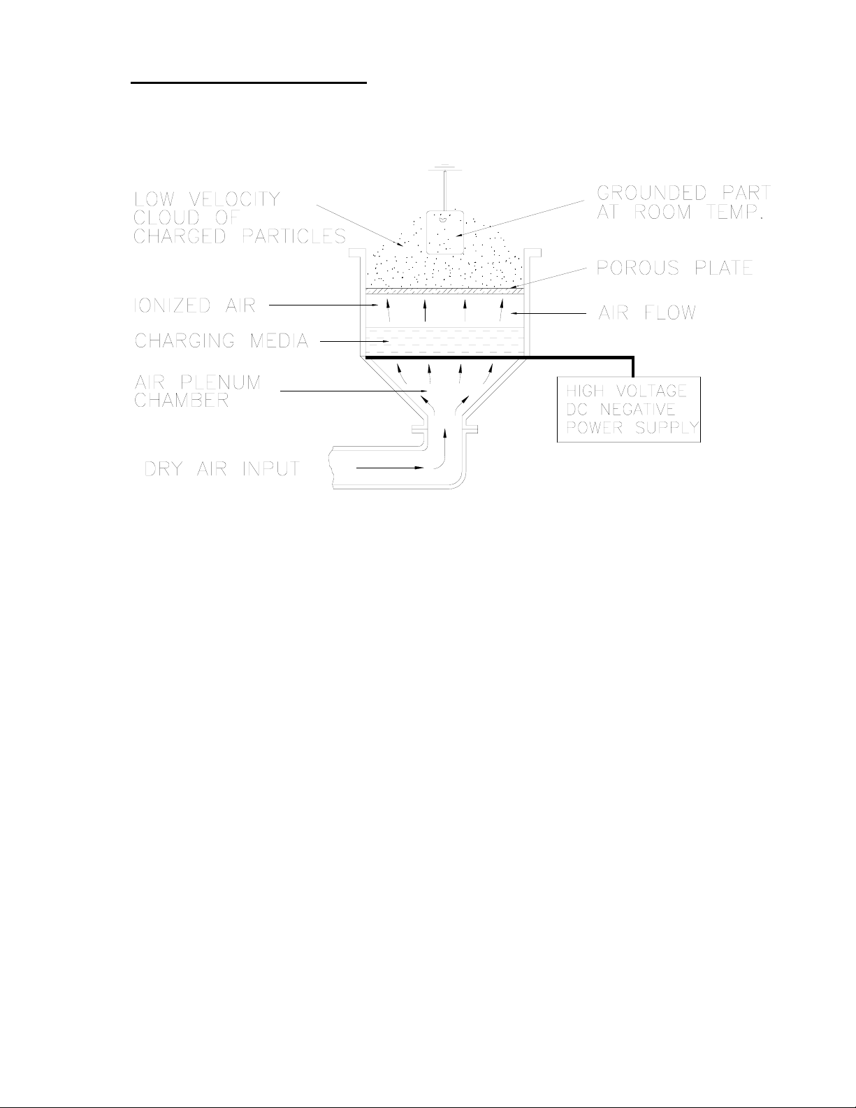
3 OPERATING PRINCIPLES
3.1 SCHEMATIC DIAGRAM OF AN ELECTROSTATIC COATER
3.2 PROCESS DESCRIPTION
Powder particles are aerated in a fluidizing chamber and are electrostatically charged
by ionized air forced through a porous plate at the base of the chamber. As the
powder particles become charged, they repel each other to such a degree that they rise
above the chamber forming a cloud or veil of charged particles. When a grounded
object is placed in this cloud, or conveyed through this cloud, the charged powder
particles, because of their opposite potential, are attracted to it. As the particles
become attached to the object, they form a uniform coating, being more attracted to
exposed areas than to those already insulated. The longer the object is exposed to the
cloud, the thicker the coating becomes, until saturation eventually takes place.
Coating thickness is controlled by applied voltage to the charging media and exposure
time to the cloud. Because of the high voltage capability of the charging media, a
sufficiently great potential exists between it and most substrates to permit even natural
insulators to be coated. Unlike equipment with exposed electrodes, Electrostatic
Technology, Inc.'s unique air ionization process charges the powder without permitting
the powder, the object, or the operator to come in contact with the charging media.

Electrostatic Technology, Inc FlexiCoat® Model 300 Coater
Serial #20158 3
4 GENERAL SAFETY
4.1 INTRODUCTION
This section contains general study instructions for using your Electrostatic
Technology, Inc. (ETI) equipment. Task-and-equipment-specific warnings are
included in other sections of this manual where appropriate. Note all warnings and
follow all instructions carefully. Failure to do so may result in personal injury, death,
or property damage.
To use this equipment safely:
• Read and become familiar with the general safety instructions provided in this
section of the manual before installing, operating, maintaining, or repairing this
equipment.
• Read and carefully follow the instructions given throughout this manual for
performing specific tasks and working with specific equipment.
• Store this manual within easy reach of personnel installing, operating,
maintaining, or repairing this equipment.
• Follow all applicable procedures required by your company, industry standards,
and government or regulatory agencies. Refer to the National Fire Protection
Association (NFPA) standard 33 and to federal, state, regulatory agency, and
local codes for rules and regulations covering installation and operation of
powder coating systems.
• Obtain and read Material Safety Data Sheets (MSDS) for all materials used.

Electrostatic Technology, Inc FlexiCoat®Model 300 Coater
4 Serial #20158
4.2 SAFETY SYMBOLS
Become familiar with the safety symbols presented in this section. These symbols
will alert you to safety hazards and conditions that may result in personal injury,
death, or property and equipment damage.
WARNING: Failure to observe this warning may result in personal in
personal injury, death, or equipment damage.
WARNING: Risk of electrical shock. Failure to observe this warning
may result in personal injury, death, or equipment damage.
WARNING: Disconnect equipment from line voltage. Failure to
observe this warning may result in personal injury, death, or equipment
damage.
WARNING: Risk of explosion of fire. Fire, open flames and smoking
prohibited.
WARNING Wear protective clothing, safety goggles, and approved
respiratory protection. Failure to observe may result in serious injury.
WARNING: System or material pressurized. Release pressure. Failure
to observe this warning may result in serious injury of death.
CAUTION: Failure to observe may result in equipment damage.
4.3 QUALIFIED PERSONAL
"Qualified Personnel" is defined here as individuals who thoroughly understand the
equipment and its safe operation, maintenance, and repair. Qualified personnel are
physically capable of performing the required tasks, familiar with all relevant safety
rules and regulations, and have been trained to safely install, operate, maintain, and
repair the equipment. It is the responsibility of the company operating the
equipment to see that its personnel meet these requirements.

Electrostatic Technology, Inc FlexiCoat® Model 300 Coater
Serial #20158 5
4.4 INTENDED USE
WARNING: Use of this equipment in ways other than described in this manual
may result in personal injury, death, or property and equipment damage. Use
this equipment only as described in this manual.
ETI cannot be responsible for injuries or damages resulting from nonstandard,
unintended applications of its equipment. This equipment is designed and
intended only for the purpose described in this manual. Uses not described in
this manual are considered unintended uses and may result in serious personal
injury, death, or property damage. Unintended uses may result from taking the
following actions:
• Making changes to equipment that have not been recommended or described in
this manual or using parts that are not genuine ETI replacement parts.
• Failure to make sure that auxiliary equipment complies with approval agency
requirements, local codes, and all applicable safety standards.
• Using materials or auxiliary equipment that are inappropriate or incompatible
with your ETI equipment.
• Allowing unqualified personnel to perform any task.
4.5 INSTALLATION
Read the installation section of all system components manuals before installing your
equipment. A thorough understanding of the system components and their
requirements will help you install the system safely and efficiently.
• Allow only qualified personnel to install ETI and auxiliary equipment.
• Use only approved equipment. Using unapproved equipment in an approved
system may void agency approvals.
• Make sure all equipment is rated and approved for the environment in
which you are using it.
• Follow all instructions for installing components and accessories.
• Install locking, manual, shutoff valves in the air supply lines to the system.
This allows you to relieve air pressure and lock out the pneumatic system
before undertaking maintenance and repairs.
• Install a locking disconnect switch or breaker in the service line ahead of any
electrical equipment (if applicable).

Electrostatic Technology, Inc FlexiCoat®Model 300 Coater
6 Serial #20158
4.5 INSTALLATION (continued)
• Use only electrical wire of sufficient gauge and insulation to handle the rated current
demand. All wiring must meet local codes.
• Ground all electrically conductive equipment within 10 feet (3 meters) of the coating
area. Ungrounded conductive equipment can store a static charge which could ignite
a fire or cause an explosion if a hot spark is discharged.
• Install safety interlocks which shut down the coating system if the exhaust fan fails, a
fire is detected, or other emergency situation develops.
• Make sure the coating area floor is conductive to ground and that the operator's
platform is grounded.
• Use only designated lifting points or lugs to lift and move heavy equipment. Always
balance and block loads when lifting to prevent shifting. Lifting devices must be
inspected, certified, and rated for a greater weight than the equipment being lifted.
• Protect components from damage, wear, and harsh environmental condition.
• Allow ample room for maintenance, material supply container drop-off and loading,
panel accessibility, and cover removal.
• If safety devices must be removed for installation, reinstall them immediately after
the work is completed and check them for proper functioning.
4.6 OPERATION
Only qualified personnel, physically capable of operating the equipment and with no
impairments to their judgement or reaction times, should operate this equipment.
Read all component manuals before operating a powder coating system. A thorough
understanding of all components and their operations will help you operate the
system safely and efficiently.
• Use this equipment only in the environments for which it is rated. Do not
operate this equipment in humid, flammable, or explosive environments unless it
has been rated for safe operation in these environments.
• Before starting this equipment, check all safety interlocks, fire detection systems,
and protective devices such as panels and covers (if applicable). Make sure all
devices are fully functional. Do not operate the system if these devices are not
working properly. Do not deactivate or bypass automatic safety interlocks or
locked-out electrical disconnects or pneumatic valves.

Electrostatic Technology, Inc FlexiCoat® Model 300 Coater
Serial #20158 7
4.6 OPERATION (continued)
• Know where EMERGENCY STOP buttons, shutoff valves, and fire
extinguishers are located. Make sure they work. If a component malfunctions,
shut down and lock out the equipment immediately.
• Before operating, make sure all conductive equipment in the coating area is
connected to a true earth ground.
• Never operate equipment with a known malfunction or leak.
• Do not attempt to operate electrical equipment if standing water is present.
• Never touch exposed electrical connections on equipment while the power is
ON.
• Do not operate the equipment at pressures higher than the rated maximum
working pressure of any component in the system.
• Know the pinch points, temperatures, and pressures for all equipment that you
are working with. Recognize potential hazards associated with these and
exercise appropriate caution.
• Wear shoes with conductive soles, such as leather, or use grounding straps to
maintain a connection to ground when working with or around electrostatic
equipment.
• Do not wear or carry metallic objects (jewelry or tools) while working with or
around electrostatic equipment. Ungrounded metal can store a static charge and
cause harmful shocks.
• Keep parts of the body or loose clothing away from moving equipment or parts.
Remove personal jewelry and cover or tie back long hair.
• Wear National Institute of Occupational Safety and Health (NIOSH) approved
respirators, safety glasses or goggles, and gloves while handling powder
containers, filling hoppers, operating coating equipment, and performing
maintenance or cleaning tasks. Avoid getting powder coatings on your skin.
• Do not smoke in the coating area. A lit cigarette could ignite a fire or cause an
explosion.
• If you notice electrical arcing in the coating equipment, shut down the system
immediately. An arc can cause a fire or explosion.
• Shut off electrostatic power supplies before making adjustments to powder
coating fluidized bed.

Electrostatic Technology, Inc FlexiCoat®Model 300 Coater
8 Serial #20158
4.6 OPERATION (continued)
• Shut off moving equipment before taking measurements or inspecting work
pieces.
• Wash exposed skin frequently with soap and water, especially before eating or
drinking. Do not use solvents to remove coating materials from your skin.
• Do not use high-pressure compressed air to blow powder off your skin or
clothes. High-pressure compressed air can be injected under the skin and cause
serious illness or death. Treat all high-pressure fittings and hoses as if they
could lead and cause injury.
4.7 LESS OBVIOUS DANGERS
Operators should also be aware of less obvious dangers in the workplace that often
cannot be completely eliminated:
• Exposed surfaces on the equipment which may be hot or have sharp edges and
cannot be practically safeguarded.
• Electrical equipment which may remain energized for a period of time after the
equipment has been shut off.
• Vapors and materials which may cause allergic reactions or other health
problems.
• Automatic hydraulic, pneumatic, or mechanical equipment or parts that may
move without warning.
• Unguarded, moving mechanical assemblies.
4.8 ACTION IN THE EVENT OF A SYSTEM OR COMPONENT MALFUNCTION
Do not operate a system that contains malfunctioning components. If a component
malfunctions, turn the system OFF immediately.
• Disconnect and lock out electrical power. Close and lock out hydraulic and
pneumatic shutoff valves and relieve pressures.
• Allow only qualified personnel to make repairs. Repair or replace the
malfunctioning component.

Electrostatic Technology, Inc FlexiCoat® Model 300 Coater
Serial #20158 9
4.9 MAINTENANCE & REPAIR
Allow only qualified personnel to perform maintenance, troubleshooting, and
repair tasks.
• Always wear appropriate protective devices and use safety devices when
working on this equipment
• Follow the recommended maintenance procedures in your equipment
manuals.
• Do not service or adjust any equipment unless another person trained in first
aid and CPR is present.
• Use only genuine ETI replacement parts. Using unapproved parts or making
unapproved modifications to equipment may void agency approvals and create
safety hazards.
• Disconnect, lock out, and tag electrical power at a disconnect or breaker in
the service line ahead of electrical equipment before servicing.
• Do not attempt to service electrical equipment if there is standing water
present. Do not service electrical equipment in a high-humidity environment.
• Use tools with insulated handles when working with electrical equipment.
• Do not attempt to service a moving piece of equipment. Shut off the
equipment and lock out power. Secure equipment to prevent uncontrolled
movement.
• Relieve air pressures before servicing equipment. Follow the specific
instructions in this manual.
• Make sure that the area or room where you are working is sufficiently
ventilated.
• If a "power on" test is required, perform the test carefully and then shut off and
lock out power as soon as the test is over.
• Connect all disconnected equipment ground cables and wires after servicing
the equipment. Ground all conductive equipment.
• Check interlock systems periodically to ensure their effectiveness.

Electrostatic Technology, Inc FlexiCoat®Model 300 Coater
10 Serial #20158
4.9 MAINTENANCE & REPAIR (continued)
WARNING: Operating faulty electrostatic equipment is hazardous and can cause
electrocution, fire, or explosion. Make resistance checks part of your
periodic maintenance program.
• Do not store flammable materials in the coating area or room. Keep
containers or flammable materials far enough away from the Coater to prevent
their inclusion in a fire. If a fire or explosion occurs, flammable materials in
the area will increase the chances and the extent of personal injuries and
property damage.
• Practice good housekeeping procedures. Do not allow dust or powder
coatings to accumulate in the coating area or on electrical equipment. Read
this information carefully and follow instruction.
4.10 DISPOSAL
Dispose of equipment and materials used in operation and cleaning according to your
local regulations.

Electrostatic Technology, Inc FlexiCoat® Model 300 Coater
Serial #20158 11
IMPORTANT: Provide a proper ground connection for the plug
equipment ground wire. Polarity of the receptacle
must be according to code.
5 AIR AND ELECTRICAL REQUIREMENTS
5.1 FLEXICOAT®
5.1.1 Air
10 scfm @ 80 psi minimum/100 psi maximum. A 1/2 inch minimum air line
should be connected to the FlexiCoat®Coating Machine.
It is strongly recommended that the air supply to be connected to the
FlexiCoat®Coating Machine be clean, dry and free of particles or oil.
5.1.2 Electrical
220 Volts, 50 Hertz, 1-Phase, 20 Amp circuit is required (an eight foot cord
with a three wire duplex plug is provided).

Electrostatic Technology, Inc FlexiCoat®Model 300 Coater
12 Serial #20158
6 DESCRIPTION OF COMPONENTS
6.1 FLEXICOAT®300 COATING STATION
The coating machine is complete with Coating Bed, Powder Feed Chamber, High
Voltage Multiplier, Air Flow Meter, Vibrator (to insure proper fluidization), and
Tooling Plate with Low Velocity Plume (cover). The coating chamber is of a
patented design that insures that neither powder, substrate being processed, nor
foreign objects can contact the charging media.
6.1.1 Tooling Plate
A plastic Tooling Plate is mounted over the top of the Coating Bed to increase
the efficiency of the powder coating process.
The Tooling Plate restricts the opening out of which charged powder comes up
from the fluidizing bed. This causes the powder to be directed toward the
specific part to be coated instead of using the entire bed area.
In this Machine, the Low Velocity Plume (cover) is attached to the Tooling
Plate.
6.1.1.1 Low Velocity Plume (cover)
This is a plastic plate with a slot, mounted on the Tooling Plate to control
powder deposition for a specific part.
6.1.2 Powder Level Sensor
A powder level sensing unit (Dwyer Photohelic®Gauge/Switch) monitors the
powder level to maintain an optimum level of powder in the coating bed to
ensure coating repeatability and uniformity from part to part. As the powder
level drops, the level sensor sends an electronic message to activate the Powder
Pump Solenoid. The Powder Pump replenishes the powder into the Coating Bed.
When the proper level is obtained, the Powder Pump shuts off.
The Powder Level Sensor consists of a control sensor and two inputs which read
the difference between the pressure at the powder level in the Coating Bed and
atmospheric pressure outside the Coating Bed area. The range of the control
sensor has been pre-set at the ETI factory and should not be touched or changed
without consulting ETI personnel. The Photohelic®Gauge/Switch which
indicates the pressure range is located on the Control Panel on the left side of the
FlexiCoat®300 Cabinet. When the Indicator needle comes in contact with the
Left Set-Point Indicator, the Powder Pump goes "ON" and stays "ON" until the
Indicator Needle comes in contact with the Right Set-Point Indicator, at which
time it shuts "OFF", until the Indicator Needle makes contact with the Left Set-
Point Indicator again.

Electrostatic Technology, Inc FlexiCoat® Model 300 Coater
Serial #20158 13
6.1.2 Powder Level Sensor (continued)
Refer to the Dwyer Photohelic®Gauge/Switch Section in the Appendix of this
manual for more specific information on this unit.
NOTE: The range of the control sensor has been pre-set at the ETI
factory and should not be touched or changed without
consulting ETI personnel.
6.1.3 Powder Feed Chamber
Powder replenishment is supplied on demand from the Coater Level Sensor and
Powder Pump via the Powder Feed Chamber, attached to the Coater Bed. A
mixture of powder and air enters the Powder Feed Chamber. Once in the
chamber, the powder settles to the bottom and falls into the Coater Bed, while
the air exits to the exhaust outlet.
6.1.4 Optional Conventional Fluid Bed
The Conventional Fluid Bed (C.F.B.) is a non-electrostatic fluidizing dipping
bed that mounts over the electrostatic fluidized bed. There is an operator control
switch to run the High voltage “OFF”, and allow the C.F.B. to be used. The
C.F.B. has 8 inch deep side walls which holds the powder in a lightly fluidized
condition for the dipping of a pre-heated part.
The C.F.B. option is intended for heavy powder build applications on a hot part.
NOTE: CARE MUST BE TAKEN DURING DIPPING APPLICATIONS
TO NEVER TOUCH THE POROUS PLATE LOCATED AT
THE BOTTOM OF THE FLUIDIZING BED WITH A HOT
PART OR IT WILL MELT.
6.2 FLEXICOAT®COLLECTOR
The 500 CFM Collector Module uses a ¾ HP motor to drive the Exhaust Fan. The
Exhaust Fan pulls air from Powder Application Hood (Canopy) and into the (2)
Cartridge Filters. The air passes through the Cartridge Filters and is forced through
the Final Filter. The clean, powder free air is returned to the surroundings.
Excess powder (not adhering to the parts) is carried by the air flowing through the
Hood to the Cartridge Filters, where it collects on the outer surfaces. When activated
(by pressing the Filter Pulse Manual Valve pushbutton), the pulse valves force air
from the Pulse Valve Air Manifold through the Cartridge Filter in the opposite
direction of normal flow. The pulse airflow cleans accumulated powder from the
Cartridge Filter media. The powder falls to the bottom of the Collector Module and
into the storage container where it can be recovered and recycled or discarded.

Electrostatic Technology, Inc FlexiCoat®Model 300 Coater
14 Serial #20158
6.2 FLEXICOAT®COLLECTOR (continued)
A Differential Pressure Gauge is located on the side of the Collector Module. This
gauge provides an indication of cleanliness of the Filter Cartridges. A normal reading
would be between 0 and 3.5. A reading above 3.5 would indicate the Filter
Cartridges are not being cleaned well enough. This would require resetting the unit
so the reverse cleaning pulses are more frequent and/or increasing the air pressure to
the pulse circuit.
6.3 FLUIDIZING HOPPER/POWDER FEED PUMP
The Fluidizing Hopper is located behind the coating bed. It is a fluidized hopper with
a pump, which is manually loaded with either virgin powder or a combination of
virgin and reclaimed material. Powder is automatically fed into the coating bed by
the Powder Feed Pump on demand, by a signal from the Powder Level Sensor. The
feeder hopper holds approximately 1.2 cubic feet (.034 cubic meters) of powder.
IMPORTANT: DO NOT DROP ANY FOREIGN MATTER INTO THE
POWDER AS THIS WILL JAM THE FEEDER.

Electrostatic Technology, Inc FlexiCoat® Model 300 Coater
Serial #20158 15
7 INSTALLATION
These instructions for installing, operating and maintaining the FlexiCoat® Model 300 Coater
must be followed for its safe and efficient operation. In particular, precautions should be
observed whenever the unit is operated. Study this manual before installing or operating
equipment. Some voltages employed in this equipment are high. Remember that any source of
voltage can be hazardous.
7.1 LOCATION
1. Place "FlexiCoat®" and ancillary equipment on a level surface at the desired
location. Refer to Floor Plan Drawing in the Appendix of this manual.
2. Look over the entire Collector Module and refer to the Customer Product
Manual #303 867B (located in the Appendix) for installation information not
specified in this manual. Although your machine may be shipped pre-
assembled, please read through this manual before installing.
7.2 AIR CONNECTIONS
E.T.I. supplies the Poly-Flo tubing for all air connections. Refer to the Pneumatic
Schematic in the Appendix of this manual.
1. Check that all pneumatic hoses are connected securely throughout the
machine.
2. Connect the 1/2 inch air supply hose to the main air inlet located on the right
front Powder Collector leg.
NOTE: If Dry inert gas is used, consult the E.T.I. factory.
7.3 ELECTRICAL CONNECTION
1. Connect the Booth and Electrical Panel to a true earth ground.
2. Connect the FlexiCoat® Model 300 Coater electrical cord to a receptacle
rated: 220 Volts, 50 Hertz, 1-Phase, 20 Amp.
CAUTION: ALL RECEPTACLES MUST HAVE A PROPER
GROUND CONNECTION.

Electrostatic Technology, Inc FlexiCoat®Model 300 Coater
16 Serial #20158
7.4 CONTROLS
7.4.1 Footswitch
1. Locate the Coater Footswitch and position in front of the Coater Station.
The Footswitch is already pre-wired to the electrical controls.
7.4.2 Settings
1. Press COLLECTOR START pushbutton on the Control Panel. This will
turn the Blower Motor "ON".
2. Turn COATER BED ON/OFF Switch to "ON" position.
3. Adjust the Filter Pulser Air Pressure to 30 psi (2 bar).
4. Adjust the Coating Bed Air Pressure to 45 psi (3 bar).
5. If using Coating Bed in the "Hot Dip Mode", turn HIGH VOLTAGE
ON/OFF Switch to "OFF" position.
6. If using Coating Bed in the "High Voltage Mode", turn HIGH
VOLTAGE ON/OFF Switch to "ON" position.
7. Press Footswitch to apply fluidizing air in the "Hot Dip Mode" or
fluidizing air and High Voltage in the "High Voltage Mode".
CAUTION: Never turn the High Voltage ON/OFF Switch to "ON"
when in the "Hot Dip Mode".
7.5 FLUIDIZING HOPPER/POWDER FEED PUMP
1. Locate the Fluidizing Hopper/Powder Feed Pump behind the FlexiCoat®
Model 300 Coating System.
2. Connect the ETI supplied 2 inch diameter vent hose from the lid of
Fluidizing Hopper to the Powder Collector.
3. Connect the 2 ETI supplied Poly-Flo tubing lines to (1) the Air Pump located
on the lid of the Fluidizing Hopper and (2) the Fluidizer located on the lower
part of the Fluidizing Hopper.
4. Connect the ETI supplied blue hose from the Powder Pump located on the lid
of the Fluidizing Hopper to the Feeder Tube located on top of the Coating
Bed.

Electrostatic Technology, Inc FlexiCoat® Model 300 Coater
Serial #20158 17
7.6 POWDER MAINTENANCE
Most powders are hygroscopic. An attempt should be made to finish the day's run
with a minimum amount of powder left in the Fluidizing Hopper. All powder
containers (bags, barrels, hoppers, etc.) should be kept tightly closed.
NOTE: Do not mix different types of powder.
Electrostatic Technology, Inc FlexiCoat®Model 300 Coater
18 Serial #20158
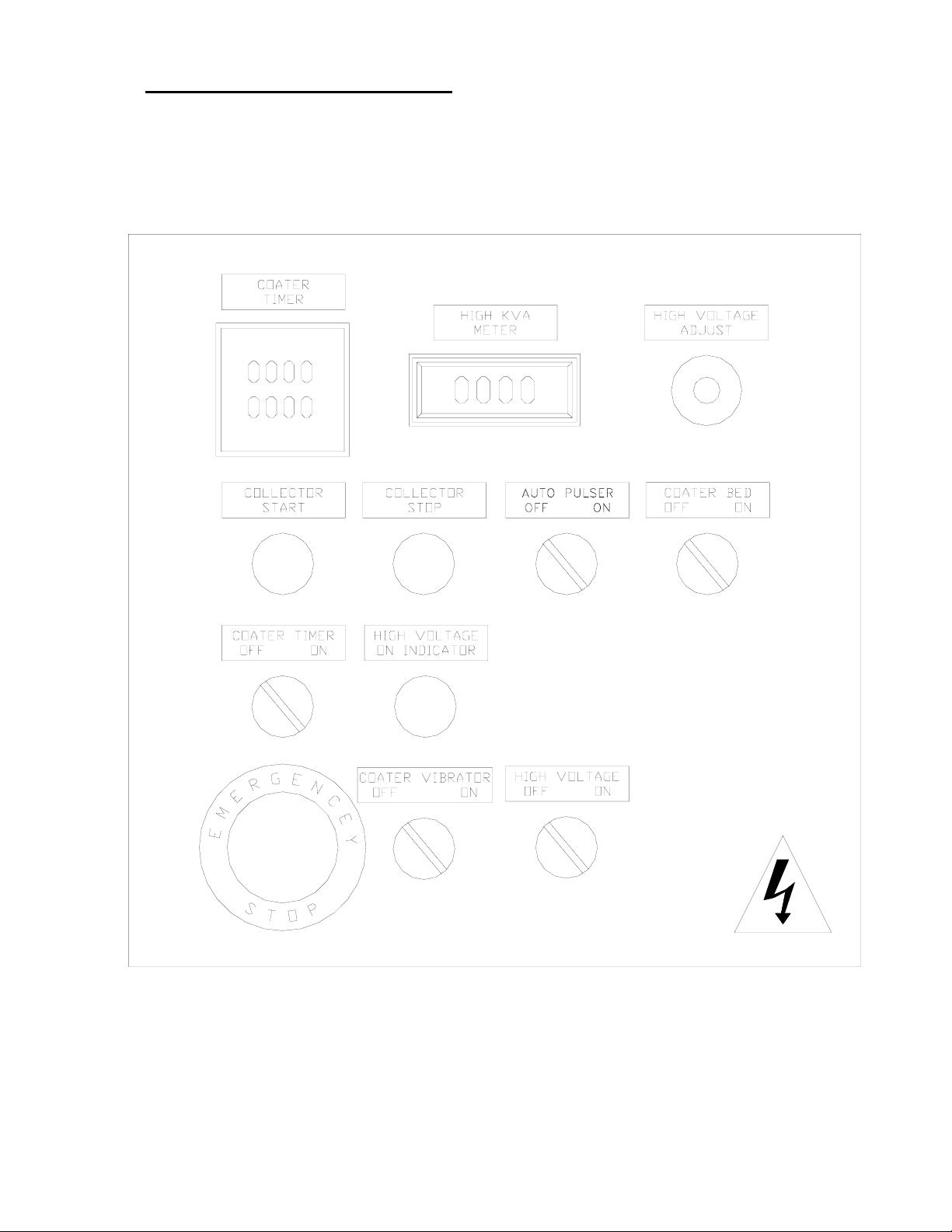
8 DESCRIPTION OF CONTROLS
8.1 POWDER COLLECTOR AND COATER CONTROL PANEL ILLUSTRATION
Table of contents
Other Electrostatic Technology Industrial Equipment manuals


