Electrostatic Technology Trickle Impregnation System User manual

Electrostatic Technology, Inc. Trickle Impregnation System
Serial #18028 i
TABLE OF CONTENTS
1 INTRODUCTION................................................................................................................................................. 1
2 SHIPPING ............................................................................................................................................................. 1
3 GENERAL SAFETY ............................................................................................................................................ 2
3.1 INTRODUCTION.............................................................................................................................................. 2
3.2 SAFETY SYMBOLS......................................................................................................................................... 3
3.3 QUALIFIED PERSONAL................................................................................................................................. 3
3.4 INTENDED USE ............................................................................................................................................... 4
3.5 INSTALLATION............................................................................................................................................... 4
3.6 OPERATION ..................................................................................................................................................... 5
3.7 LESS OBVIOUS DANGERS............................................................................................................................ 7
3.8 ACTION IN THE EVENT OF A SYSTEM OR COMPONENT MALFUNCTION........................................ 7
3.9 MAINTENANCE & REPAIR ........................................................................................................................... 7
3.10 DISPOSAL.................................................................................................................................................... 9
4 SPECIFIC EQUIPMENT SAFETY.................................................................................................................. 10
4.1 GENERAL ....................................................................................................................................................... 10
4.2 RESIN .............................................................................................................................................................. 10
4.2.1 Employee Health..................................................................................................................................... 10
4.2.1.1 Inhalation .............................................................................................................................................................10
4.2.1.2 Skin Contact.........................................................................................................................................................10
4.2.1.3 Skin Absorption ..................................................................................................................................................10
4.2.1.4 Eye Contact..........................................................................................................................................................11
4.2.1.5 Ingestion...............................................................................................................................................................11
4.2.2 First Aid Procedures............................................................................................................................... 11
4.2.2.1 Inhalation .............................................................................................................................................................11
4.2.2.2 Skin Contact.........................................................................................................................................................11
4.2.2.3 Eye Contact..........................................................................................................................................................11
4.2.2.4 Ingestion...............................................................................................................................................................11
4.2.3 Special Protection................................................................................................................................... 11
4.2.4 Precautions............................................................................................................................................. 11
4.2.5 Material Safety Data Sheets (MSDS)...................................................................................................... 12
5 AIR AND ELECTRICAL REQUIREMENTS ................................................................................................ 13
5.1 TRICKLE IMPREGNATION MACHINE ...................................................................................................... 13
5.1.1 Air ........................................................................................................................................................... 13
5.1.2 Electrical ................................................................................................................................................ 13
5.2 INDUCTION HEATER................................................................................................................................... 13
5.2.1 Electrical ................................................................................................................................................ 13
5.2.2 Water ...................................................................................................................................................... 13
5.2.2.1 Closed Loop Induction Heater Cooling System ...................................................................................................13
5.2.2.2 Tower Water Requirements for Induction Heater Cooling ..................................................................................13
5.3 FIRE EXTINGUISHER SYSTEM .................................................................................................................. 13
5.3.1 Electrical ................................................................................................................................................ 13
6 MECHANICAL FUNCTION: SEQUENCE AND DESCRIPTION.............................................................. 14
6.1 LOAD AREA................................................................................................................................................... 14
6.2 INDUCTION HEATER STATION................................................................................................................. 14
6.3 RESIN TRICKLE STATION .......................................................................................................................... 14
6.3.1 Resin Level Sensor.................................................................................................................................. 14
6.4 CURE MODULE ............................................................................................................................................. 15
6.5 FINAL COOL MODULE ................................................................................................................................ 15
6.6 AIR FILTERS .................................................................................................................................................. 15
6.7 FIRE EXTINGUISHER SYSTEM .................................................................................................................. 15
6.8 DISTILLED WATER SYSTEM ..................................................................................................................... 16
6.9 INDUCTION HEATER COOLING WATER................................................................................................. 16

Electrostatic Technology, Inc. Trickle Impregnation System
ii Serial #18028
6.10 MAIN CONTROL CABINET .................................................................................................................... 16
7 DESCRIPTION OF CONTROLS..................................................................................................................... 17
7.1 MAIN CONTROL CABINET ......................................................................................................................... 17
7.1.1 Main Electrical Control.......................................................................................................................... 17
7.2 OPERATOR CONTROL PANEL ................................................................................................................... 17
7.2.1 Operator Control Panel Illustration....................................................................................................... 17
7.2.2 Operator Control Panel Controls........................................................................................................... 18
7.3 STATION BEACON ....................................................................................................................................... 19
7.4 INDUCTION HEATER CONTROLS............................................................................................................. 19
7.5 PNEUMATIC CONTROLS ............................................................................................................................ 20
7.6 FIRE EXTINGUISHER SYSTEM CONTROLS ............................................................................................ 21
8 PANELVIEW SCREENS................................................................................................................................... 22
8.1 MAIN MENU SCREEN .................................................................................................................................. 23
8.2 MACHINE START-UP SCREEN................................................................................................................... 24
8.3 MACHINE AUTO START/STOP & STATUS SCREEN .............................................................................. 26
8.4 MACHINE – MANUAL CONTROL & SETUP SCREEN ............................................................................ 28
8.5 MACHINE – TRICKLE PUMP CALIBRATION SCREEN .......................................................................... 30
8.6 ALARM ACTIVE SCREEN ........................................................................................................................... 32
8.7 ALARM HISTORY SCREEN......................................................................................................................... 33
8.8 MACHINE I.D. SCREEN................................................................................................................................ 34
8.9 ALARM BANNER SCREEN.......................................................................................................................... 35
9 PREPARATION FOR OPERATION............................................................................................................... 38
9.1 INITIAL SYSTEM INSTALLATION ............................................................................................................ 38
9.2 INDUCTION HEATER................................................................................................................................... 39
10 START-UP AND OPERATION PROCEDURE.............................................................................................. 40
10.1 OVERVIEW................................................................................................................................................ 40
10.2 MANUAL MODE....................................................................................................................................... 41
10.2.1 Induction Heater..................................................................................................................................... 42
10.3 AUTO MODE ............................................................................................................................................. 43
11 MACHINE SHUT DOWN PROCEDURE....................................................................................................... 44
11.1 AUTO MODE SHUTDOWN ..................................................................................................................... 44
11.2 MANUAL MODE SHUTDOWN............................................................................................................... 44
11.3 LOCKOUT.................................................................................................................................................. 45
12 MAINTENANCE................................................................................................................................................ 46
12.1 GENERAL .................................................................................................................................................. 46
12.2 COMPRESSED AIR SYSTEM .................................................................................................................. 46
12.2.1 Air Line ................................................................................................................................................... 46
12.2.2 Air Filters and Lubricator ...................................................................................................................... 46
12.3 TRICKLE STATION .................................................................................................................................. 46
12.3.1 Switching to Spare Pump and Lines ....................................................................................................... 46
12.4 INDUCTION HEATER .............................................................................................................................. 47
12.5 COOLING BLOWERS............................................................................................................................... 47
12.6 ROTO-FLO TRANSPORT CONVEYOR.................................................................................................. 47
12.7 MOTORS AND GEARS............................................................................................................................. 47
13 PREVENTATIVE MAINTENANCE SCHEDULE ........................................................................................ 48
13.1 DAILY ........................................................................................................................................................ 48
13.2 WEEKLY .................................................................................................................................................... 48
13.3 MISCELLANEOUS.................................................................................................................................... 48
13.4 LUBRICATION CHART ........................................................................................................................... 48
14 PART CHANGEOVER...................................................................................................................................... 49
14.1 CHANGEOVER PROCEDURE................................................................................................................. 49
14.1.1 Bearing Blocks........................................................................................................................................ 49

Electrostatic Technology, Inc. Trickle Impregnation System
Serial #18028 iii
14.1.2 Lifting Rails ............................................................................................................................................ 49
15 TROUBLE SHOOTING .................................................................................................................................... 50
15.1 CONVEYOR CLUTCH .............................................................................................................................. 50
15.2 BAD PART ................................................................................................................................................. 50
16 PATENTS ............................................................................................................................................................ 52
17 SPARE PARTS LIST ......................................................................................................................................... 53
18 FLOOR PLAN .................................................................................................................................................... 62
19 PNEUMATIC SCHEMATIC ............................................................................................................................ 62
20 ELECTRICAL SCHEMATIC........................................................................................................................... 62
21 MANUFACTURER’S MANUALS ................................................................................................................... 62


Electrostatic Technology, Inc. Trickle Impregnation System
Serial #18028 1
1 INTRODUCTION
This Instruction Manual must be studied and followed for the safe and efficient operation of the
"Trickle Impregnation System". Study this manual before locating and installing the equipment.
ELECTROSTATIC TECHNOLOGY, INC.
A SUBSIDIARY OF NORDSON CORPORATION
4 PIN OAK DRIVE
BRANFORD, CT 06405
TELEPHONE: 203-488-8112
FAX: 203-483-8777
In future correspondence, please refer to the MODEL (Trickle Impregnation System) and
SERIAL NUMBER 18028 (located on the Main Electrical Enclosure) of the "TRICKLE
IMPREGNATION SYSTEM".
2 SHIPPING
Sometimes equipment can be damaged in transit. An inspection of the shipping crate should be
made upon delivery, and when equipment is removed, it should be carefully inspected to make
sure the unit is in good condition. If the equipment is damaged, the carrier's claim agent should
be requested to prepare a report, a copy of which should be sent to:
ELECTROSTATIC TECHNOLOGY, INC
A SUBSIDIARY OF NORDSON CORPORATION
4 PIN OAK DRIVE
BRANFORD, CT 06405
Electrostatic Technology, Inc will then advise concerning repairs and replacements.

Electrostatic Technology, Inc Trickle Impregnation System
2 Serial #18028
3 GENERAL SAFETY
3.1 INTRODUCTION
This section contains general study instructions for using your Electrostatic
Technology, Inc. (ETI) equipment. Task-and-equipment-specific warnings are
included in other sections of this manual where appropriate. Note all warnings and
follow all instructions carefully. Failure to do so may result in personal injury, death,
or property damage.
To use this equipment safely:
• Read and become familiar with the general safety instructions provided in this
section of the manual before installing, operating, maintaining, or repairing this
equipment.
• Read and carefully follow the instructions given throughout this manual for
performing specific tasks and working with specific equipment.
• Store this manual within easy reach of personnel installing, operating,
maintaining, or repairing this equipment.
• Follow all applicable procedures required by your company, industry standards,
and government or regulatory agencies. Refer to the National Fire Protection
Association (NFPA) standard 33 and to federal, state, regulatory agency, and
local codes for rules and regulations covering installation and operation of
powder coating systems.
• Obtain and read Material Safety Data Sheets (MSDS) for all materials used.
Electrostatic Technology, Inc. Trickle Impregnation System
Serial #18028 3
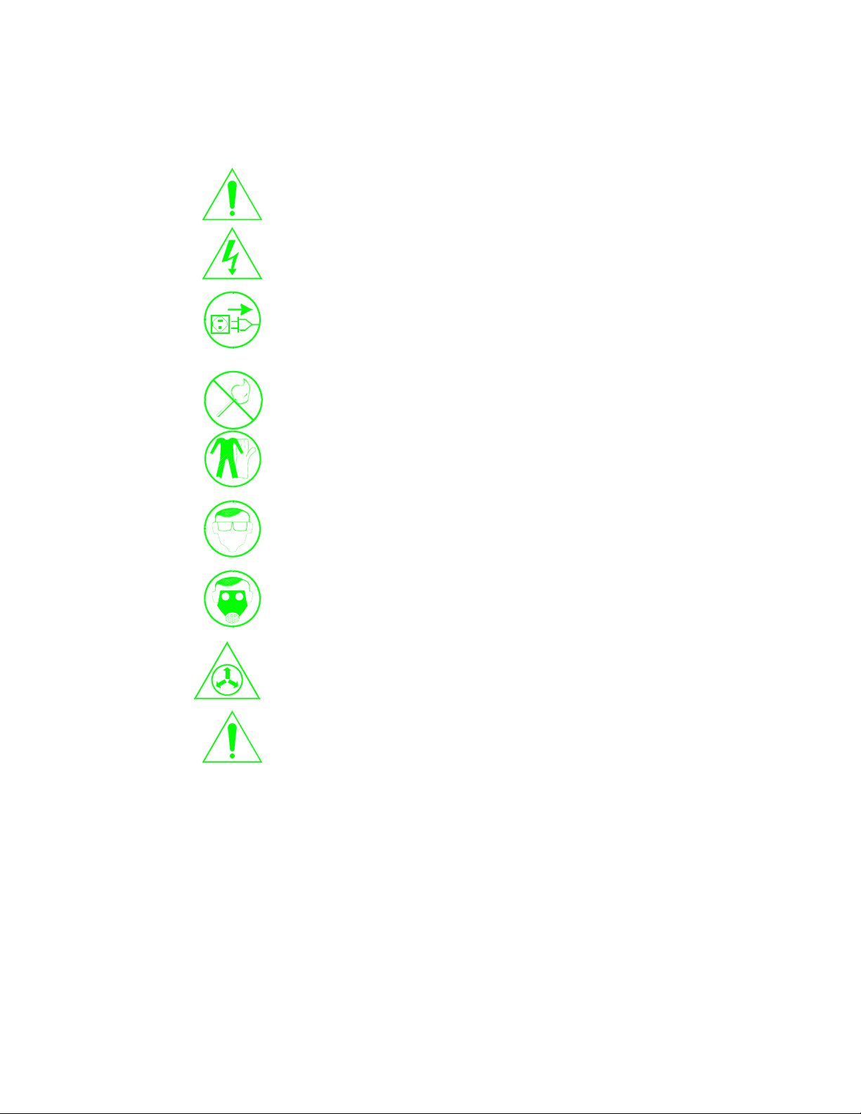
3.2 SAFETY SYMBOLS
Become familiar with the safety symbols presented in this section. These symbols
will alert you to safety hazards and conditions that may result in personal injury,
death, or property and equipment damage.
WARNING: Failure to observe this warning may result in personal in
personal injury, death, or equipment damage.
WARNING: Risk of electrical shock. Failure to observe this warning
may result in personal injury, death, or equipment damage.
WARNING: Disconnect equipment from line voltage. Failure to
observe this warning may result in personal injury, death, or equipment
damage.
WARNING: Risk of explosion of fire. Fire, open flames and smoking
prohibited.
WARNING Wear protective clothing, safety goggles, and approved
respiratory protection. Failure to observe may result in serious injury.
WARNING: System or material pressurized. Release pressure. Failure
to observe this warning may result in serious injury of death.
CAUTION: Failure to observe may result in equipment damage.
3.3 QUALIFIED PERSONAL
"Qualified Personnel" is defined here as individuals who thoroughly understand the
equipment and its safe operation, maintenance, and repair. Qualified personnel are
physically capable of performing the required tasks, familiar with all relevant safety
rules and regulations, and have been trained to safely install, operate, maintain, and
repair the equipment. It is the responsibility of the company operating the
equipment to see that its personnel meet these requirements.

Electrostatic Technology, Inc Trickle Impregnation System
4 Serial #18028
3.4 INTENDED USE
WARNING: Use of this equipment in ways other than described in this manual
may result in personal injury, death, or property and equipment damage. Use
this equipment only as described in this manual.
ETI cannot be responsible for injuries or damages resulting from nonstandard,
unintended applications of its equipment. This equipment is designed and
intended only for the purpose described in this manual. Uses not described in
this manual are considered unintended uses and may result in serious personal
injury, death, or property damage. Unintended uses may result from taking the
following actions:
• Making changes to equipment that have not been recommended or described in
this manual or using parts that are not genuine ETI replacement parts.
• Failure to make sure that auxiliary equipment complies with approval agency
requirements, local codes, and all applicable safety standards.
• Using materials or auxiliary equipment that are inappropriate or incompatible
with your ETI equipment.
• Allowing unqualified personnel to perform any task.
3.5 INSTALLATION
Read the installation section of all system components manuals before installing your
equipment. A thorough understanding of the system components and their
requirements will help you install the system safely and efficiently.
• Allow only qualified personnel to install ETI and auxiliary equipment.
• Use only approved equipment. Using unapproved equipment in an approved
system may void agency approvals.
• Make sure all equipment is rated and approved for the environment in
which you are using it.
• Follow all instructions for installing components and accessories.
• Install locking, manual, shutoff valves in the air supply lines to the system.
This allows you to relieve air pressure and lock out the pneumatic system
before undertaking maintenance and repairs.
• Install a locking disconnect switch or breaker in the service line ahead of any
electrical equipment.

Electrostatic Technology, Inc. Trickle Impregnation System
Serial #18028 5
3.5 INSTALLATION (continued)
• Use only electrical wire of sufficient gauge and insulation to handle the rated current
demand. All wiring must meet local codes.
• Ground all electrically conductive equipment within 10 feet (3 meters) of the trickle
impregnation area. Ungrounded conductive equipment can store a static charge,
which could ignite a fire or cause an explosion if a hot spark is discharged.
• Install safety interlocks, which shut down the Trickle Impregnation System if the
exhaust fan fails, a fire is detected, or other emergency situation develops.
• Make sure the coating area floor is conductive to ground and that the operator's
platform is grounded.
• Use only designated lifting points or lugs to lift and move heavy equipment. Always
balance and block loads when lifting to prevent shifting. Lifting devices must be
inspected, certified, and rated for a greater weight than the equipment being lifted.
• Protect components from damage, wear, and harsh environmental condition.
• Allow ample room for maintenance, material supply container drop-off and loading,
panel accessibility, and cover removal.
• If safety devices must be removed for installation, reinstall them immediately after
the work is completed and check them for proper functioning.
3.6 OPERATION
Only qualified personnel, physically capable of operating the equipment and with no
impairments to their judgement or reaction times, should operate this equipment.
Read all component manuals before operating a powder coating system. A thorough
understanding of all components and their operations will help you operate the
system safely and efficiently.
• Use this equipment only in the environments for which it is rated. Do not
operate this equipment in humid, flammable, or explosive environments unless it
has been rated for safe operation in these environments.
• Before starting this equipment, check all safety interlocks, fire detection systems,
and protective devices such as panels and covers. Make sure all devices are fully
functional. Do not operate the system if these devices are not working properly.
Do not deactivate or bypass automatic safety interlocks or locked-out electrical
disconnects or pneumatic valves.

Electrostatic Technology, Inc Trickle Impregnation System
6 Serial #18028
3.6 OPERATION (continued)
• Know where EMERGENCY STOP buttons, shutoff valves, and fire
extinguishers are located. Make sure they work. If a component malfunctions,
shut down and lock out the equipment immediately.
• Before operating, make sure all conductive equipment in the trickle impregnation
area is connected to a true earth ground.
• Never operate equipment with a known malfunction or leak.
• Do not attempt to operate electrical equipment if standing water is present.
• Never touch exposed electrical connections on equipment while the power is
ON.
• Do not operate the equipment at pressures higher than the rated maximum
working pressure of any component in the system.
• Know the pinch points, temperatures, and pressures for all equipment that you
are working with. Recognize potential hazards associated with these and
exercise appropriate caution.
• Do not wear or carry metallic objects (jewelry or tools) while working with or
around the induction heating unit.
• Keep parts of the body or loose clothing away from moving equipment or parts.
Remove personal jewelry and cover or tie back long hair.
• Wear National Institute of Occupational Safety and Health (NIOSH) approved
respirators, safety glasses or goggles, and gloves while handling powder
containers, filling hoppers, operating coating equipment, and performing
maintenance or cleaning tasks. Avoid getting powder coatings on your skin.
• Do not smoke in the trickle impregnation area. A lit cigarette could ignite a fire
or cause an explosion.
• If you notice electrical arcing in the trickle impregnation area, shut down the
system immediately. An arc can cause a fire or explosion.
• Shut off moving equipment before taking measurements or inspecting work
pieces.
• Wash exposed skin frequently with soap and water, especially before eating or
drinking. Do not use solvents to remove coating materials from your skin.

Electrostatic Technology, Inc. Trickle Impregnation System
Serial #18028 7
3.6 OPERATION (continued)
• Do not use high-pressure compressed air to blow resin off your skin or clothes.
High-pressure compressed air can be injected under the skin and cause serious
illness or death. Treat all high-pressure fittings and hoses as if they could lead
and cause injury.
3.7 LESS OBVIOUS DANGERS
Operators should also be aware of less obvious dangers in the workplace that often
cannot be completely eliminated:
• Exposed surfaces on the equipment which may be hot or have sharp edges and
cannot be practically safeguarded.
• Electrical equipment which may remain energized for a period of time after the
equipment has been shut off.
• Vapors and materials which may cause allergic reactions or other health
problems.
• Automatic hydraulic, pneumatic, or mechanical equipment or parts that may
move without warning.
• Unguarded, moving mechanical assemblies.
3.8 ACTION IN THE EVENT OF A SYSTEM OR COMPONENT MALFUNCTION
Do not operate a system that contains malfunctioning components. If a component
malfunctions, turn the system OFF immediately.
• Disconnect and lock out electrical power. Close and lock out hydraulic and
pneumatic shutoff valves and relieve pressures.
• Allow only qualified personnel to make repairs. Repair or replace the
malfunctioning component.
3.9 MAINTENANCE & REPAIR
Allow only qualified personnel to perform maintenance, troubleshooting, and
repair tasks.
• Always wear appropriate protective devices and use safety devices when
working on this equipment
• Follow the recommended maintenance procedures in your equipment
manuals.

Electrostatic Technology, Inc Trickle Impregnation System
8 Serial #18028
3.9 MAINTENANCE & REPAIR (continued)
• Do not service or adjust any equipment unless another person trained in first
aid and CPR is present.
• Use only genuine ETI replacement parts. Using unapproved parts or making
unapproved modifications to equipment may void agency approvals and create
safety hazards.
• Disconnect, lock out, and tag electrical power at a disconnect or breaker in
the service line ahead of electrical equipment before servicing.
• Do not attempt to service electrical equipment if there is standing water
present. Do not service electrical equipment in a high-humidity environment.
• Use tools with insulated handles when working with electrical equipment.
• Do not attempt to service a moving piece of equipment. Shut off the
equipment and lock out power. Secure equipment to prevent uncontrolled
movement.
• Relieve air pressures before servicing equipment. Follow the specific
instructions in this manual.
• Make sure that the area or room where you are working is sufficiently
ventilated.
• If a "power on" test is required, perform the test carefully and then shut off and
lock out power as soon as the test is over.
• Connect all disconnected equipment ground cables and wires after servicing
the equipment. Ground all conductive equipment.
• Check interlock systems periodically to ensure their effectiveness.
WARNING: Operating faulty equipment is hazardous and can cause electrocution,
fire, or explosion. Make resistance checks part of your periodic
maintenance program.
• Do not store flammable materials in the trickle impregnation area or room.
Keep containers or flammable materials far enough away from the System to
prevent their inclusion in a fire. If a fire or explosion occurs, flammable
materials in the area will increase the chances and the extent of personal
injuries and property damage.
• Practice good housekeeping procedures. Do not allow resin coating to
accumulate in the trickle or cure area or on electrical equipment. Read this
information carefully and follow instruction.

Electrostatic Technology, Inc. Trickle Impregnation System
Serial #18028 9
3.10 DISPOSAL
Dispose of equipment and materials used in operation and cleaning according to your
local regulations.

Electrostatic Technology, Inc Trickle Impregnation System
10 Serial #18028
4 SPECIFIC EQUIPMENT SAFETY
4.1 GENERAL
SOME VOLTAGES EMPLOYED IN PARTS OF THIS TRICKLE
IMPREGNATION SYSTEM ARE HIGH. REMEMBER THAT ANY SOURCE
OF VOLTAGE CAN BE HAZARDOUS.
ONLY RELIABLE, DEPENDABLE, TRAINED EMPLOEES SHOULD BE
GIVEN THE RESPONSIBILITY OF OPERATION AND MAINTENANCE OF
THIS SYSTEM.
ALL SECTIONS OF THIS MANUAL SHOULD BE STUDIED AND ALL
POTENTIAL SAFETY HAZARDS IDENTIFIED AND UNDERSTOOD
PRIOR TO INSTALLATION AND OPERATION OF THIS EQUIPMENT.
4.2 RESIN
As with all volatile materials, there is a potential vapor hazard. In the case of a liquid
spill, clean the material up and dispose of it in accordance with applicable local, state
and federal ordinances.
There is potential vapor explosion hazard. Resin should be kept away from sparks or
open flames. Personnel should not be permitted to smoke in the trickle impregnation
area.
4.2.1 Employee Health
Repeated excessive exposures to resin products may cause central nervous
system, liver, and kidney effects and respiratory or eye irritation. Personnel
may be susceptible to the following effects of overexposure to material:
4.2.1.1 Inhalation
Breathing high concentrations of vapors or mist may cause nose and
throat irritation. May affect the brain or nervous system, causing
dizziness, headache, or nausea.
4.2.1.2 Skin Contact
Prolonged or repeated contact can cause moderate irritation,
defatting, and dematitis. Strict attention to proper personal hygiene
practice is recommended.
4.2.1.3 Skin Absorption
A single prolonged exposure is not likely to result in the material
being absorbed through skin in harmful amounts.

Electrostatic Technology, Inc. Trickle Impregnation System
Serial #18028 11
4.2.1.4 Eye Contact
May cause slight eye irritation.
4.2.1.5 Ingestion
May cause gastrointestinal irritation.
4.2.2 First Aid Procedures
4.2.2.1 Inhalation
Remove individual to fresh air. If breathing is difficult, give oxygen.
If not breathing, give artificial respiration. Consult a physician.
4.2.2.2 Skin Contact
Wash skin thoroughly with soap and flush with plenty of water for 15
minutes. Remove contaminated clothing and shoes. Wash and
thoroughly clean contaminated clothes before re-use. Consult a
physician if required.
4.2.2.3 Eye Contact
Flush eye gently with plenty of clean water for 15 minutes. If
irritation persists, contact a physician.
4.2.2.4 Ingestion
If swallowed, consult a physician. Do not induce vomiting or give
anything by mouth because material can enter the lungs and cause
severe lung damage.
4.2.3 Special Protection
Protective equipment may be worn in order to minimize contact with skin, eyes
or clothing. Masks, rubber gloves, eye goggles and coveralls may be suitable.
4.2.4 Precautions
Personnel should observe the following when working with resin materials:
WASH ALL SURFACES IN CONTACT WITH RESIN MATERIAL
THOROUGHLY BEFORE EATING OR SMOKING.
NO SMOKING IN THE VICINITY OF THE TRICKLE
IMPREGNATION AREA.
AVOID INHALATION OF FUMES.

Electrostatic Technology, Inc Trickle Impregnation System
12 Serial #18028
4.2.5 Material Safety Data Sheets (MSDS)
For every powder, which is used in the coating equipment, a Material Safety
Data Sheet should be obtained from the powder manufacturer. Personnel should
be aware of potential hazards, as well as proper methods of handling powdered
materials.

Electrostatic Technology, Inc. Trickle Impregnation System
Serial #18028 13
5 AIR AND ELECTRICAL REQUIREMENTS
5.1 TRICKLE IMPREGNATION MACHINE
5.1.1 Air
A clean, oil free, dry supply of compressed air must be provided using 1 inch
I.D. line capable of supplying 50 scfm @ 80 psi minimum to 100 psi maximum.
5.1.2 Electrical
480 Volts, 60 Hertz, 3-Phase, 100 Amp service Plant Power must be supplied to
the Main Disconnect on the rear of the machine.
5.2 INDUCTION HEATER
5.2.1 Electrical
Power for the Induction Heaters is supplied from the main power input specified
in Section 6.1.2 above.
5.2.2 Water
5.2.2.1 Closed Loop Induction Heater Cooling System
Distilled water is required for the Closed Loop Induction Heater
Cooling System. Approximately 10 gallons of distilled water is
required to fill the system.
5.2.2.2 Tower Water Requirements for Induction Heater Cooling
Customer must supply 7.5 gallons/minute at 30 psi of cooling water
(85º F maximum, 45º F minimum) to the Heat Exchanger for the
Closed Loop Induction Heater Cooling System.
5.3 FIRE EXTINGUISHER SYSTEM
5.3.1 Electrical
110 Volts, 60 Hertz, 1-Phase, Plant Power must be supplied to the Fire
Extinguisher System Control Unit.

Electrostatic Technology, Inc Trickle Impregnation System
14 Serial #18028
6 MECHANICAL FUNCTION: SEQUENCE AND DESCRIPTION
6.1 LOAD AREA
Parts are automatically placed on a load ramp where they are cycled through a
separator and loaded onto the E.T.I. Roto-Flo Conveyor via an escapement device.
The conveyor moves parts through each station of the Trickle Impregnation System.
NOTE: The drive system is located at this station.
6.2 INDUCTION HEATER STATION
This Induction Heater is a 100 kHz/30 kW unit. The Induction Heater raises the
temperature of each part to approximately 350° F. The hood for this module must be
closed to allow the unit to operate.
Adjustment controls for the Induction Heater is located on the Operator Control
Panel. For information on temperature adjustment, refer to the Heuttinger Induction
Heater manual in the Manufacturer’s Manual Section of this Manual.
6.3 RESIN TRICKLE STATION
After the parts are heated they are conveyed through the Trickle Station. Four
pairs of resin deposition nozzles are mounted on a traverse assembly that
consists of a plate riding on a pair of shafts with ball bushings. The trickle plate
is driven by a ball screw/servo motor arrangement so that it exactly follows the
speed of the rotating armatures for 7.5 inches (3 pitches of the transport screw) to
allow time for the resin to trickle onto the parts as they rotate. The four pairs of
nozzles will trickle resin onto four (4) parts at a time for 18 seconds (6 seconds
per pitch) and then will retract to the home position. A Fiber Optic Sensor will
signal when the process is to start again.
The Trickle Station will be supplied with two 5-gallon stainless steel reservoirs
with handles, each with a pneumatically driven stirring bar, 2 peristaltic pumps
and two sets of supply tubing. This redundancy allows the Operator to continue
running while one system is being filled and/or cleaned. It also includes
stainless steel troughs and shielding around the trickle traverse assembly
designed to contain and collect un-deposited resin and return it to the reservoir.
Tubes will be adjustable in and out and feed tubes will be of a “tube within a
tube” design.
6.3.1 Resin Level Sensor
A Resin Level Sensing Unit (Ultrasonic Level Sensor) located on top of the
Resin Holding Tank will light a Blue Warning Light if there is a “LOW RESIN”
condition in the Holding Tank.

Electrostatic Technology, Inc. Trickle Impregnation System
Serial #18028 15
6.4 CURE MODULE
The Cure Module, located just after the Trickle Station, allows time for the resin on
each part to cure. The insulated hood should always be in place while the machine is
running, to retain the heat.
6.5 FINAL COOL MODULE
In this module the part passes through an aerodynamically designed directional vane,
directing air around each coated part. The air is moved using a rotor type exhausting
fan. When the part leaves this module, it is cool enough to be handled by hand.
6.6 AIR FILTERS
A Particle Air Filter and a Coalescing Air Filter are installed at the main air supply
drop for the System (the main air drop is located behind the machine at the Cure
Module). These filters are provided to remove foreign particles and oil from the air
entering the System.
For specific information on the Particle Filter and Coalescing Filter, refer to the
Manufacturer's Manuals Section of this Manual.
6.7 FIRE EXTINGUISHER SYSTEM
A separate free-standing Fire Extinguisher System provided to spray CO² (Carbon
Dioxide) in various stations on the machine in the case of fire. The unit (and
Operating Controls) is located behind the machine in the Cure Section.
There are two (2) Heat Sensors and four (4) spray nozzles located in the Trickle
Station; one (1) Heat Sensor and two (2) spray nozzles located in the Cure Tunnel
and one (1) Heat Sensor and one (1) spray nozzle located in the Final Cool Exhaust
Duct.
The CO² (Carbon Dioxide) system is discharged when a Heat Sensor senses the
temperature in a Section of the System has exceeded the pre-set temperature setting
on that Heat Sensor. The Sensor in the Trickle Station has been set for 450° F; the
Sensor in the Cure Tunnel has been set for 600° F; and the Sensor in the Final Cool
Exhaust Duct has been set for 600° F.
In the event that a Heat Sensor senses a fire condition: an Alarm Horn/Strobe Light
is energized; the exhaust air is shut down; the Trickle Impregnation Machine is shut
down; and the CO² (Carbon Dioxide) system is discharged.
NOTE: if the CO² (Carbon Dioxide) system is discharged, the METRON
PROTRACTOR in the Electric Actuator MUST be replaced
Please refer to the Fire Control Service/ANSUL information in the Appendix of this
Manual for information on the Fire Extinguisher System.

Electrostatic Technology, Inc Trickle Impregnation System
16 Serial #18028
6.8 DISTILLED WATER SYSTEM
The water that flows through the coils of the Induction Heaters is contained in a
closed loop system. This system should be filled with about 10 gallons of distilled
water.
6.9 INDUCTION HEATER COOLING WATER
Heat in the distilled water system is removed by customer-supplied cooling water
fed to one path through a heat exchanger as the distilled water flows through the
other path in the heat exchanger.
Locate the view hole in the front panel of the machine, at the Cure Module. This
view hole has a label marked "Distilled Water Level". A distilled water temperature
gauge is located on the sight gauge. The normal water temperature is 60°- 90°F.
The water level can be checked by looking at the "HIGH/LOW" marking on the
sight gauge.
6.10 MAIN CONTROL CABINET
The Main Control Cabinet for the Trickle Impregnation System houses the machine
electrical circuitry. Refer to the Electrical Schematics in the Appendix.
Mounted above the Main Control Cabinet is the Operator Main Control Panel. All
the operator controls for equipment operation are located on this Operator Main
Control Panel.
This manual suits for next models
1
Table of contents
Other Electrostatic Technology Industrial Equipment manuals


Popular Industrial Equipment manuals by other brands


Peter electronic
Peter electronic VersiComb II 230-3 Installation and commissioning instructions

Toptech
Toptech MultiLoad II installation guide

Apator
Apator ARS 00/60 mm pro OPERATING AND INSTALLATION Manual

Siemens
Siemens 8US1903-3AB00 operating instructions

Trotec
Trotec SpeedMarker 300 fiber operating manual

Zimmer
Zimmer GEH6000IL Series Installation and operating instructions