Electrostatic Technology MR240 User manual

Electrostatic Technology, Inc. MR240 Coating System
Serial #15784 i
TABLE OF CONTENTS
1 INTRODUCTION ..................................................................................................................1
2 SHIPPING............................................................................................................................... 1
3 OPERATING PRINCIPLES .................................................................................................. 2
3.1 SCHEMATIC DIAGRAM OF AN ELECTROSTATIC COATER .................................. 2
3.2 PROCESS DESCRIPTION ................................................................................................ 3
4 GENERAL SAFETY.............................................................................................................. 4
4.1 INTRODUCTION .............................................................................................................. 4
4.2 SAFETY SYMBOLS.......................................................................................................... 5
4.3 QUALIFIED PERSONNEL ............................................................................................... 6
4.4 INTENDED USE................................................................................................................6
4.5 INSTALLATION ............................................................................................................... 6
4.6 OPERATION...................................................................................................................... 8
4.7 LESS OBVIOUS DANGERS............................................................................................. 9
4.8 ACTION IN THE EVENT OF A SYSTEM OR COMPONENT MALFUNCTION ...... 10
4.9 MAINTENANCE & REPAIR.......................................................................................... 10
4.10 DISPOSAL ................................................................................................................... 11
5 AIR, ELECTRICAL AND WATER REQUIREMENTS .................................................... 12
5.1 POWDER COATING MACHINE ................................................................................... 12
5.1.1 Air ............................................................................................................................. 12
5.1.2 Electrical ................................................................................................................... 12
5.1.3 Water......................................................................................................................... 12
5.1.3.1 Closed Loop Induction Heater and Induction Heater Cooling System................. 12
5.1.3.2 Deionized Water Requirements:........................................................................... 12
5.2 INDUCTION HEATER.................................................................................................... 12
6 MECHANICAL FUNCTION: SEQUENCE & DESCRIPTION........................................ 13
6.1 LOAD STATION ............................................................................................................. 13
6.2 COATING STATION ...................................................................................................... 13
6.3 O.D. CLEANING STATION ........................................................................................... 14
6.4 I.D. CLEANING STATION............................................................................................. 14
6.5 INDUCTION HEATING STATION ............................................................................... 14
6.6 CURE TRANSFER STATION ........................................................................................ 15
6.7 TIP CLEANING STATION ............................................................................................. 15
6.8 POWDER MANAGEMENT SYSTEM ........................................................................... 15
6.9 REFRIGERANT AIR DRYER......................................................................................... 16
6.10 DEIONIZED WATER SYSTEM ................................................................................. 16
6.11 CURE OVEN/FINAL COOL CONVEYOR SYSTEM ............................................... 16
7 DESCRIPTION OF CONTROLS ........................................................................................ 17
7.1 MAIN CONTROL CABINET.......................................................................................... 17
7.1.1 Electrical Control...................................................................................................... 17
7.2 OPERATOR CONTROL PANEL.................................................................................... 17
7.2.1 Electrical Controls .................................................................................................... 18
7.3 STATION BEACON ........................................................................................................ 20
7.4 PNEUMATIC CONTROLS ............................................................................................. 21
7.5 PNEUMATIC CONTROLS PANEL ............................................................................... 24
7.6 POWDER MANAGEMENT SYSTEM CONTROLS.................................................... 25
8 PREPARATION FOR OPERATION................................................................................... 26

Electrostatic Technology, Inc. MR240 Coating System
ii Serial #15784
8.1 GENERAL........................................................................................................................ 26
8.2 INITIAL SYSTEM INSTALLATION ............................................................................. 26
8.3 LOAD STATION ............................................................................................................. 28
8.4 COATER........................................................................................................................... 28
8.4.1 Coating Bed .............................................................................................................. 28
8.4.2 Powder Deposition.................................................................................................... 28
8.4.2.1 Fluidizing Air........................................................................................................ 28
8.4.2.2 Powder Level ........................................................................................................ 28
8.4.3 High Voltage............................................................................................................. 29
8.5 CLEANERS...................................................................................................................... 29
8.5.1 O.D. Cleaner Adjusting............................................................................................. 29
8.5.2 I.D. Cleaner Adjusting .............................................................................................. 29
8.5.3 Tip Cleaner Adjusting............................................................................................... 30
8.6 INDUCTION HEATER.................................................................................................... 30
8.7 CURE OVEN/FINAL COOL/CONVEYOR.................................................................... 30
8.8 POWDER MANAGEMENT SYSTEM ........................................................................... 30
8.8.1 Loading Powder........................................................................................................ 30
8.8.2 Powder Maintenance................................................................................................. 31
9 SPECIFIC EQUIPMENT SAFETY ..................................................................................... 32
9.1 GENERAL........................................................................................................................ 32
9.2 POWDER.......................................................................................................................... 32
9.2.1 Employee Health....................................................................................................... 32
9.2.1.1 Inhalation .............................................................................................................. 32
9.2.1.2 Skin Contact.......................................................................................................... 32
9.2.1.3 Eye Contact........................................................................................................... 33
9.2.2 First Aid Procedures ................................................................................................. 33
9.2.2.1 Inhalation .............................................................................................................. 33
9.2.2.2 Skin Contact.......................................................................................................... 33
9.2.2.3 Eye Contact........................................................................................................... 33
9.2.3 Special Protection ..................................................................................................... 33
9.2.4 Precautions................................................................................................................ 33
9.2.5 Material Safety Data Sheets (MSDS) ....................................................................... 33
10 PANELVIEW SCREENS..................................................................................................... 34
10.1 MACHINE OPERATION SCREEN............................................................................ 36
10.2 MACHINE OPERATION PANELVIEW SCREEN.................................................... 36
10.3 PARTS LOADER SCREEN......................................................................................... 37
10.4 PARTS COATING SCREEN....................................................................................... 38
10.5 O.D. CLEANING SCREEN......................................................................................... 39
10.6 I.D. CLEANING SCREEN........................................................................................... 40
10.7 INDUCTION HEATING SCREEN ............................................................................. 41
10.8 PARTS UNLOADER SCREEN................................................................................... 42
10.9 CURE OVEN SCREEN ............................................................................................... 43
10.10 PART FIXTURE CLEANER SCREEN....................................................................... 44
10.11 ALARM HISTORY SCREEN ..................................................................................... 45
10.12 ALARM BANNER SCREEN ...................................................................................... 45
11 STARTUP PROCEDURE .................................................................................................... 46
11.1 OVERVIEW ................................................................................................................. 46
11.2 MANUAL OPERATION ............................................................................................. 48
11.2.1 LOADING STATION .............................................................................................. 49
11.2.2 COATING STATION .............................................................................................. 49

Electrostatic Technology, Inc. MR240 Coating System
Serial #15784 iii
11.2.3 #1 O.D. CLEANING STATION .............................................................................. 50
11.2.4 I.D. CLEANING STATION..................................................................................... 50
11.2.5 INDUCTION HEATER STATION ......................................................................... 50
11.2.6 UNLOADING STATION ........................................................................................ 51
11.2.7 FIXTURE CLEANING STATION .......................................................................... 51
11.2.8 CURE OVEN SCREEN ........................................................................................... 51
11.3 AUTOMATIC OPERATION....................................................................................... 52
12 STATION SHUTDOWN PROCEDURE............................................................................. 55
12.1 AUTOMATIC OPERATION SHUTDOWN ............................................................... 55
12.2 MANUAL OPERATION SHUTDOWN ..................................................................... 55
12.3 POWDER HANDLING AT SHUTDOWN ................................................................. 56
12.4 LOCKOUT ................................................................................................................... 57
13 MAINTENANCE ................................................................................................................. 58
13.1 GENERAL.................................................................................................................... 58
13.2 COMPRESSED AIR SYSTEM.................................................................................... 58
13.2.1 Air Line..................................................................................................................... 58
13.2.2 Refrigerant Air Dryer................................................................................................ 58
13.3 FLUIDIC BED.............................................................................................................. 59
13.3.1 Installation of Porous Plate ....................................................................................... 59
13.4 POWDER MANAGEMENT SYSTEM ....................................................................... 61
13.5 POWDER LEVEL SENSOR........................................................................................ 61
13.6 O.D. CLEANER ........................................................................................................... 61
13.7 INDUCTION HEATER................................................................................................ 62
13.8 CURE OVEN/FINAL COOL CONVEYOR................................................................ 62
13.9 PROGRAMMABLE CONTROLLER ......................................................................... 62
13.10 MAIN INDEXING DRIVE .......................................................................................... 62
13.11 MOTORS AND GEARS .............................................................................................. 62
14 PREVENTATIVE MAINTENANCE SCHEDULE ............................................................ 63
14.1 DAILY .......................................................................................................................... 63
14.2 WEEKLY...................................................................................................................... 63
14.3 MISCELLANEOUS ..................................................................................................... 63
14.4 LUBRICATION CHART............................................................................................. 64
15 ALARM MESSAGES .......................................................................................................... 65
16 TROUBLE SHOOTING....................................................................................................... 88
17 PATENT INFORMATION .................................................................................................. 94
18 SPARE PARTS..................................................................................................................... 95
19 MANUFACTURER’S MANUALS ................................................................................... 101
20 FLOOR PLAN.................................................................................................................... 103
21 ELECTRICAL AND PNEUMATIC SCHEMATICS........................................................ 103


Electrostatic Technology, Inc. MR240 Coating System
Serial #15784 1
1 INTRODUCTION
This Instruction Manual must be studied and followed for the safe and efficient operation of
the " MR240 Coating System". Study this manual before locating and installing the
equipment.
ELECTROSTATIC TECHNOLOGY, INC.
A SUBSIDIARY OF NORDSON CORPORATION
4 PIN OAK DRIVE
BRANFORD, CT 06405
TELEPHONE: 203-488-8112
FAX: 203-483-8777
In future correspondence, please refer to the MODEL (MR240 Coating System) and
SERIAL NUMBER 15784 (located on the rear of the Coater) of the "STATOR COATING
SYSTEM".
2 SHIPPING
Sometimes equipment can be damaged in transit. An inspection of the shipping crate should
be made upon delivery, and when equipment is removed, it should be carefully inspected to
make sure that the unit is in good condition. If the equipment is damaged, the carrier's claim
agent should be requested to prepare a report, a copy of which should be sent to:
ELECTROSTATIC TECHNOLOGY, INC.
A SUBSIDIARY OF NORDSON CORPATION
4 PIN OAK DRIVE
BRANFORD, CT 06405
Electrostatic Technology, Inc. will then advise concerning repairs and replacements.
Electrostatic Technology, Inc. MR240 Coating System
2 Serial #15784
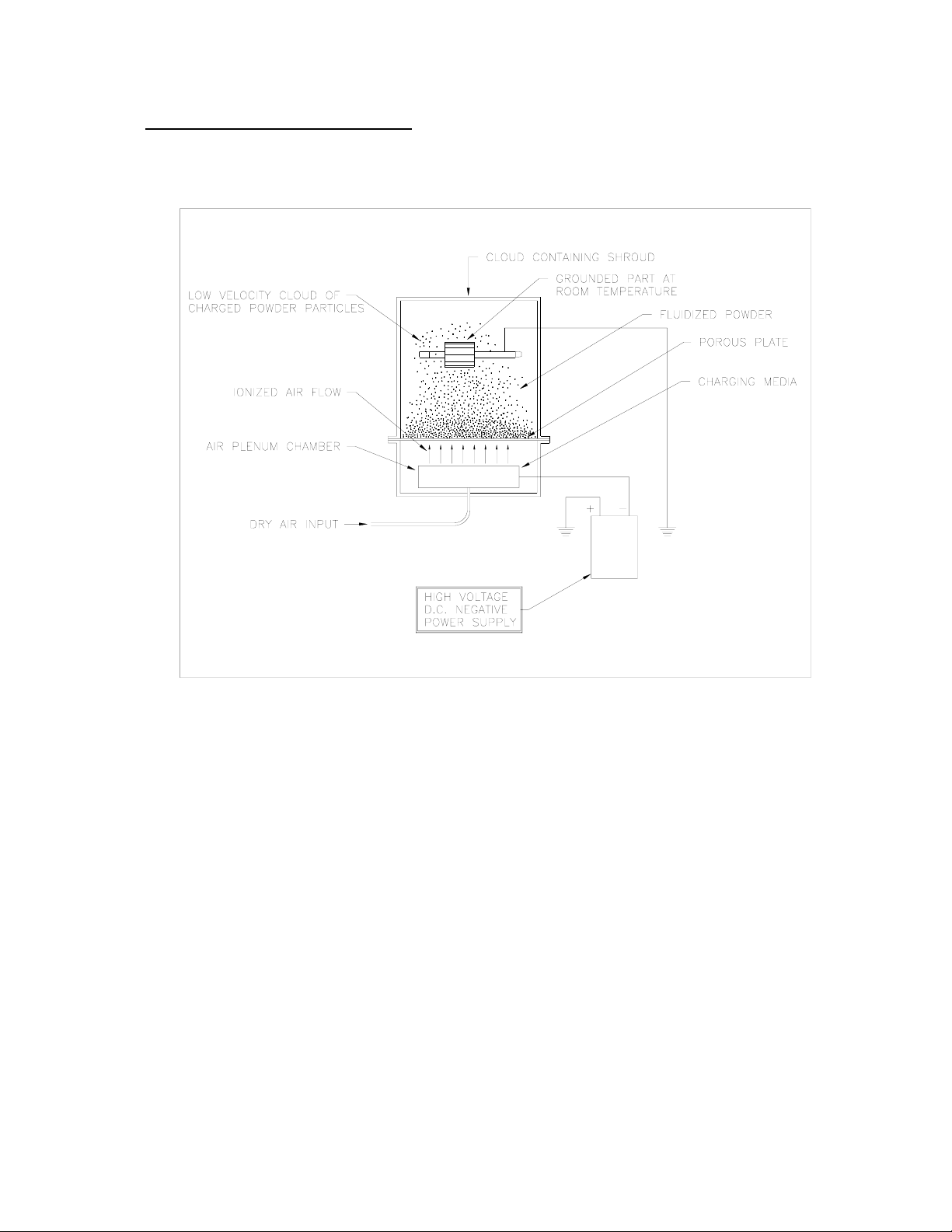
3 OPERATING PRINCIPLES
3.1 SCHEMATIC DIAGRAM OF AN ELECTROSTATIC COATER

Electrostatic Technology, Inc. MR240 Coating System
Serial #15784 3
3.2 PROCESS DESCRIPTION
Powder particles are aerated in a fluidizing chamber and are electrostatically charged
by ionized air forced through a porous plate at the base of the chamber. As the
powder particles become charged, they repel each other to such a degree that they rise
above the chamber forming a cloud or veil of charged particles. When a grounded
object is placed in this cloud, or conveyed through this cloud, the charged powder
particles, because of their opposite potential, are attracted to it. As the particles
become attached to the object, they form a uniform coating, being more attracted to
exposed areas than to those already insulated. The longer the object is exposed to the
cloud, the thicker the coating becomes, until saturation eventually takes place.
Coating thickness is controlled by applied voltage to the charging media and exposure
time to the cloud. Because of the high voltage capability of the charging media, a
sufficiently great potential exists between it and most substrates to permit even
natural insulators to be coated. Unlike equipment with exposed electrodes,
Electrostatic Technology, Inc.'s unique air ionization process charges the powder
without permitting the powder, the object, or the operator to come in contact with the
charging media.

Electrostatic Technology, Inc. MR240 Coating System
4 Serial #15784
4 GENERAL SAFETY
4.1 INTRODUCTION
This section contains general study instructions for using your Electrostatic
Technology, Inc. (ETI) equipment. Task-and-equipment-specific warnings are
included in other sections of this manual where appropriate. Note all warnings and
follow all instructions carefully. Failure to do so may result in personal injury, death,
or property damage.
To use this equipment safely:
• Read and become familiar with the general safety instructions provided in this
section of the manual before installing, operating, maintaining, or repairing this
equipment.
• Read and carefully follow the instructions given throughout this manual for
performing specific tasks and working with specific equipment.
• Store this manual within easy reach of personnel installing, operating,
maintaining, or repairing this equipment.
• Follow all applicable procedures required by your company, industry standards,
and government or regulatory agencies. Refer to the National Fire Protection
Association (NFPA) standard 33 and to federal, state, regulatory agency, and local
codes for rules and regulations covering installation and operation of powder
coating systems.
• Obtain and read Material Safety Data Sheets (MSDS) for all materials used.

Electrostatic Technology, Inc. MR240 Coating System
Serial #15784 5
4.2 SAFETY SYMBOLS
Become familiar with the safety symbols presented in this section. These symbols
will alert you to safety hazards and conditions that may result in personal injury,
death, or property and equipment damage.
WARNING: Failure to observe this warning may result in
personal injury, death, or equipment damage.
WARNING: Risk of electrical shock. Failure to observe this
warning may result in personal injury, death, or equipment
damage.
WARNING: Disconnect equipment from line voltage. Failure to
observe this warning may result in personal injury, death, or
equipment damage.
WARNING: Risk of explosion or fire. Fire, open flames and
smoking prohibited.
WARNING: Wear protective clothing, safety goggles, and
approved respiratory protection. Failure to observe this warning
may result in serious injury.
WARNING: System or material pressurized. Release pressure.
Failure to observe this warning may result in serious injury or
death.
CAUTION: Failure to observe this warning may result in
equipment damage.

Electrostatic Technology, Inc. MR240 Coating System
6 Serial #15784
4.3 QUALIFIED PERSONNEL
"Qualified Personnel" is defined here as individuals who thoroughly understand the
equipment and its safe operation, maintenance, and repair. Qualified personnel are
physically capable of performing the required tasks, familiar with all relevant safety
rules and regulations, and have been trained to safely install, operate, maintain, and
repair the equipment. It is the responsibility of the company operating the equipment
to see that its personnel meet these requirements.
4.4 INTENDED USE
WARNING: Use of this equipment in ways other than described in this
manual may result in personal injury, death, or property and equipment
damage. Use this equipment only as described in this manual.
ETI cannot be responsible for injuries or damages resulting from nonstandard,
unintended applications of its equipment. This equipment is designed and
intended only for the purpose described in this manual. Uses not described in
this manual are considered unintended uses and may result in serious personal
injury, death, or property damage. Unintended uses may result from taking
the following actions:
• Making changes to equipment that have not been recommended or described
in this manual or using parts that are not genuine ETI replacement parts.
• Failure to make sure that auxiliary equipment complies with approval agency
requirements, local codes, and all applicable safety standards.
• Using materials or auxiliary equipment that are inappropriate or incompatible
with your ETI equipment.
• Allowing unqualified personnel to perform any task.
4.5 INSTALLATION
Read the installation section of all system components manuals before installing your
equipment. A thorough understanding of the system components and their
requirements will help you install the system safely and efficiently.
• Allow only qualified personnel to install ETI and auxiliary equipment.
• Use only approved equipment. Using unapproved equipment in an approved
system may void agency approvals.

Electrostatic Technology, Inc. MR240 Coating System
Serial #15784 7
4.5 INSTALLATION (continued)
• Make sure all equipment is rated and approved for the environment in which
you are using it.
• Follow all instructions for installing components and accessories.
• Install locking, manual, shutoff valves in the air supply lines to the system.
This allows you to relieve air pressure and lock out the pneumatic system
before undertaking maintenance and repairs.
• Install a locking disconnect switch or breaker in the service line ahead of any
electrical equipment.
• Use only electrical wire of sufficient gauge and insulation to handle the rated
current demand. All wiring must meet local codes.
• Ground all electrically conductive equipment within 10 feet (3 meters) of the
coating area. Ungrounded conductive equipment can store a static charge
which could ignite a fire or cause an explosion if a hot spark is discharged.
• Install safety interlocks which shut down the coating system if the exhaust fan
fails, a fire is detected, or other emergency situation develops.
• Make sure the coating area floor is conductive to ground and that the
operator's platform is grounded.
• Use only designated lifting points or lugs to lift and move heavy equipment.
Always balance and block loads when lifting to prevent shifting. Lifting
devices must be inspected, certified, and rated for a greater weight than the
equipment being lifted.
• Protect components from damage, wear, and harsh environmental condition.
• Allow ample room for maintenance, material supply container drop-off and
loading, panel accessibility, and cover removal.
• If safety devices must be removed for installation, reinstall them immediately
after the work is completed and check them for proper functioning.

Electrostatic Technology, Inc. MR240 Coating System
8 Serial #15784
4.6 OPERATION
Only qualified personnel, physically capable of operating the equipment and with no
impairments to their judgement or reaction times, should operate this equipment.
Read all component manuals before operating a powder coating system. A thorough
understanding of all components and their operations will help you operate the system
safely and efficiently.
• Use this equipment only in the environments for which it is rated. Do not
operate this equipment in humid, flammable, or explosive environments
unless it has been rated for safe operation in these environments.
• Before starting this equipment check all safety interlocks, fire detection
systems, and protective devices such as panels and covers. Make sure all
devices are fully functional. Do not operate the system if these devices are
not working properly. Do not deactivate or bypass automatic safety interlocks
or locked-out electrical disconnects or pneumatic valves.
• Know where EMERGENCY STOP buttons, shutoff valves, and fire
extinguishers are located. Make sure they work. If a component
malfunctions, shut down and lock out the equipment immediately.
• Before operating, make sure all conductive equipment in the coating area is
connected to a true earth ground.
• Never operate equipment with a known malfunction or leak.
• Do not attempt to operate electrical equipment if standing water is present.
• Never touch the exposed electrical connections on equipment while the power
is ON.
• Do not operate the equipment at pressures higher than the rated maximum
working pressure of any component in the system.
• Know the pinch points, temperatures, and pressures for all equipment that you
are working with. Recognize potential hazards associated with these and
exercise appropriate caution.
• Wear shoes with conductive soles, such as leather, or use grounding straps to
maintain a connection to ground when working with or around electrostatic
equipment.
• Do not wear or carry metallic objects (jewelry or tools) while working with or
around electrostatic equipment. Ungrounded metal can store a static charge
and cause harmful shocks.

Electrostatic Technology, Inc. MR240 Coating System
Serial #15784 9
4.6 OPERATION (continued)
• Keep parts of the body or loose clothing away from moving equipment or
parts. Remove personal jewelry and cover or tie back long hair.
• Wear National Institute of Occupational Safety and Health (NIOSH) approved
respirators, safety glasses or goggles, and gloves while handling powder
containers, filling hoppers, operating coating equipment, and performing
maintenance or cleaning tasks. Avoid getting powder coatings on your skin.
• Do not smoke in the coating area. A lit cigarette could ignite a fire or cause
an explosion.
• If you notice electrical arcing in the coating equipment, shut down the system
immediately. An arc can cause a fire or explosion.
• Shut off electrostatic power supplies before making adjustments to powder
coating fluidized bed.
• Shut off moving equipment before taking measurements or inspecting
workpieces.
• Wash exposed skin frequently with soap and water, especially before eating or
drinking. Do not use solvents to remove coating materials from your skin.
• Do not use high-pressure compressed air to blow powder off your skin or
clothes. High-pressure compressed air can be injected under the skin and
cause serious illness or death. Treat all high-pressure fittings and hoses as if
they could lead and cause injury.
4.7 LESS OBVIOUS DANGERS
Operators should also be aware of less obvious dangers in the workplace that often
cannot be completely eliminated:
• Exposed surfaces on the equipment which may be hot or have sharp edges and
cannot be practically safeguarded.
• Electrical equipment which may remain energized for a period of time after
the equipment has been shut off.
• Vapors and materials which may cause allergic reactions or other health
problems.
• Automatic hydraulic, pneumatic, or mechanical equipment or parts that may
move without warning.
• Unguarded, moving mechanical assemblies.

Electrostatic Technology, Inc. MR240 Coating System
10 Serial #15784
4.8 ACTION IN THE EVENT OF A SYSTEM OR COMPONENT
MALFUNCTION
Do not operate a system that contains malfunctioning components. If a component
malfunctions, turn the system OFF immediately.
• Disconnect and lock out electrical power. Close and lock out hydraulic and
pneumatic shutoff valves and relieve pressures.
• Allow only qualified personnel to make repairs. Repair or replace the
malfunctioning component.
4.9 MAINTENANCE & REPAIR
Allow only qualified personnel to perform maintenance, troubleshooting, and repair
tasks.
• Always wear appropriate protective devices and use safety devices when
working on this equipment.
• Follow the recommended maintenance procedures in your equipment
manuals.
• Do not service or adjust any equipment unless another person trained in first
aid and CPR is present.
• Use only genuine ETI replacement parts. Using unapproved parts or making
unapproved modifications to equipment may void agency approvals and
create safety hazards.
• Disconnect, lock out, and tag electrical power at a disconnect or breaker in the
service line ahead of electrical equipment before servicing.
• Do not attempt to service electrical equipment if there is standing water
present. Do not service electrical equipment in a high-humidity environment.
• Use tools with insulated handles when working with electrical equipment.
• Do not attempt to service a moving piece of equipment. Shut off the
equipment and lock out power. Secure equipment to prevent uncontrolled
movement.
• Relieve air pressures before servicing equipment. Follow the specific
instructions in this manual.

Electrostatic Technology, Inc. MR240 Coating System
Serial #15784 11
4.9 MAINTENANCE & REPAIR (continued)
• Make sure that the area or room where you are working is sufficiently
ventilated.
• If a "power on" test is required, perform the test carefully and then shut off
and lock out power as soon as the test is over.
• Connect all disconnected equipment ground cables and wires after servicing
the equipment. Ground all conductive equipment.
• Check interlock systems periodically to ensure their effectiveness.
WARNING: Operating faulty electrostatic equipment is hazardous and can
cause electrocution, fire, or explosion. Make resistance checks part of your
periodic maintenance program.
• Do not store flammable materials in the coating area or room. Keep containers of
flammable materials far enough away from the coater to prevent their inclusion in
a fire. If a fire or explosion occurs, flammable materials in the area will increase
the chances and the extent of personal injuries and property damage.
• Practice good housekeeping procedures. Do not allow dust or powder coatings to
accumulate in the coating area or on electrical equipment. Read this information
carefully and follow instruction.
4.10 DISPOSAL
Dispose of equipment and materials used in operation and cleaning according to your
local regulations.

Electrostatic Technology, Inc. MR240 Coating System
12 Serial #15784
5 AIR, ELECTRICAL AND WATER REQUIREMENTS
5.1 POWDER COATING MACHINE
5.1.1 Air
A clean, oil free, dry supply of compressed air must be provided using 1 inch
I.D. line capable of supplying 75 cubic feet/minute @ 60-90 pounds per
square inch minimum.
5.1.2 Electrical
600 Volts, 60 Hertz, 3-Phase Plant Power from a 100 Amp fused disconnect
must be supplied to the Operator Station Control Cabinet.
600 Volts, 60 Hertz, 3-Phase, 60 Amps is required for the Induction Heater
Transformer.
5.1.3 Water
5.1.3.1 Closed Loop Induction Heater and Induction Heater Cooling System
Deionized water is required for the closed loop Induction Heater
cooling system. Approximately 15 gallons of deionized water are
required to fill the system.
5.1.3.2 Deionized Water Requirements:
pH between 7.0 and 9.0
Chloride Content – 20 PPM Max.
Nitrate Content – 10 PPM Max.
Sulfate Content – 1000 PPM Max.
Total Solids – 250 PPM Max.
Hardness – 250 PPM CACO Max.
Resistivity – 2500 OHM-CM Min.
5.2 INDUCTION HEATER
The Induction Heater is wired separately from the Main Electrical Control Cabinet.
The power level is controlled by the Induction Heater Power Adjust control on the
Main Control Panel.

Electrostatic Technology, Inc. MR240 Coating System
Serial #15784 13
6 MECHANICAL FUNCTION: SEQUENCE & DESCRIPTION
6.1 LOAD STATION
Stators are loaded into a V-block by customer loader assembly. The V-block carries
and loads the stators onto the slide assemblies, which indexes them to each station.
6.2 COATING STATION
The armatures are next indexed into the Coating Bed. As the stators enter the bed
area, they pass through the cloud of charged particles, which coat each stator.
A Suction Powder Pick-up hose is supplied to pick up spilled powder in this area.
The suction is available continuously when the machine is powered.
NOTE: This Pick-up hose should be used only for clean
uncontaminated powder.
Do not use it for general cleanup of dirt and trash.
A powder level sensing unit (Photohelic Gauge/Switch) controls the Powder Feeder
to assure the correct level of powder in the coating bed at all times. The Powder
Level Sensor consists of a control sensor with two inputs. The sensor reads the
difference between the air pressure at the powder level in the Coating Bed and the
ambient atmospheric pressure. The system logic requires that there be a difference
between the two pressure readings. As the readings come together, additional powder
is fed into the coating bed.
The range of the control sensor has been preset at the ETI factory and should not be
touched or changed without consulting ETI personnel. The Photohelic Gauge which
shows the pressure range is located on the front of the machine at the entrance to the
Coating Bed.
On this gauge, when the needle comes in contact with the Left Set-Point, the Powder
Feeder goes "ON". It stays on until the needle makes contact with the Right Set-
Point. This shuts off the powder feed.
Refer to the Dwyer Photohelic Gauge Manual in the Manufacturer's Manuals binder
for more specific information on this unit.

Electrostatic Technology, Inc. MR240 Coating System
14 Serial #15784
6.3 O.D. CLEANING STATION
Powder removal from the outside diameter is done in the O.D. Cleaning Station.
Parts are indexed into this station and extended out where a dual roller O.D.
Cleaner/Flapper Assembly is raised from below by a pneumatic cylinder. The drive
motor is engaged after the rollers come in contact with the parts, causing them to turn.
This action in conjunction with the flapper assemblies rubbing on the O.D. cause the
powder to be removed and vacuumed away to the Powder Management System for
reuse. The amount of pressure exerted on the part can be adjusted by changing the
setting of the O.D. Cleaner Lift Cylinder Regulator at the Main Pneumatic panel.
6.4 I.D. CLEANING STATION
Powder removal from the inside diameter and spoke area of the stator is done at the
I.D. Cleaning Station
Parts are indexed into this station and extended out into a V-block that clamps and
holds the parts. The slide assembly is retracted out of the parts and the V-block is
raised to an upper position where the actual cleaning operation takes place. Inner and
Outer I.D. Cleaner Assemblies are extended and engage the I.D. of the part. These
assemblies consist of a combination of vacuum and air knives. The air knives serve
to loosen the powder from the part and the vacuum removes it and sends it to the
Powder Management System for reuse. The V-block then lowers and the parts are
picked up by the slide assembly for indexing to the next station.
6.5 INDUCTION HEATING STATION
This Induction Heater is a 25 kW, 50 kHz unit. The purpose of the Induction
Heating Station is to heat each stator to the he proper temperature to allow the powder
to flow and eventually cure. The Hood (yellow) for this station is interlocked and
must be closed or you cannot turn "ON" the Induction Heater.
The Induction Heater Powder Adjust and the Induction Heater Power meter are
located on the Main Electrical Control Panel. For information on the Induction
Heater, refer to the Pillar Induction Heater Manual.
The power control of the Induction Heater should be set as required to heat stators to
the proper temperature as read on the Optical Pyrometer at the exit of the Induction
Heating Station. This reading is shown as the Heated Part Temperature on the
Machine Status Screen.
The powder on the stators should melt and have a wet look when the stators are index
to the loading station.

Electrostatic Technology, Inc. MR240 Coating System
Serial #15784 15
6.6 CURE TRANSFER STATION
The Cure Transfer Station, located just after the Induction Heating Station, removes
the parts from the slide assembly and transfers them onto the Cure Oven Conveyor.
Parts are indexed into the Cure Transfer Station and the slide is extended out to a
position below the Offload Stripper Assembly. The stripper assembly is lowered
from above by a pneumatic cylinder and traps the parts. The slide assembly is then
retracted out of the parts which causes them to drop a small distance (1/8" approx.)
onto the Cure Oven Conveyor. The Slide and Offload Stripper Assemblies then
retract and the Oven Conveyor indexes, carrying the parts into the oven.
6.7 TIP CLEANING STATION
The Tip Cleaning Station, located just after the Cure Transfer Station, removes any
uncured powder from the tip assemblies and also from the slide shaft covers. The
slides are extended out where they are engaged with the Tip Cleaner Assembly. This
assembly consists of vacuum/air knife tubes with internal brushes for loosening and
removing powder from the slide tip faces and bodies. Also, at this station are a set of
external brushes which loosen powder that may have migrated to the spindle shaft
covers. This powder falls to the vacuum duct below the station and is sent to the
Powder Management System for reuse.
6.8 POWDER MANAGEMENT SYSTEM
Powder management is accomplished by a vacuum system which collects powder in
ducts located around the machine and conveys it back to the lower hopper of the
powder collector. In this hopper, the collected powder is mixed with virgin powder.
The level of the powder mix is monitored by the level sensor in the hopper.
The powder is fluidized in this lower hopper by dry air which removes any remaining
moisture from the powder. This lower hopper acts as a Powder Drying Chamber.
The powder is then fed by means of a screw conveyor up to a Transition Weldment
located just above the bed. From there the powder is allowed to trickle down into the
coating bed. There is a magnet located in the Powder Feeder Transition Weldment to
collect any metallic iron contamination in the powder.
Vacuum is supplied to the system through an assembly which consists of a fan and
motor to generate the vacuum and 9 filter cartridges which retain powder within the
system. Electric and pneumatic circuitry provides a reverse pulse of air to clean the
filter cartridges. Reclaimed powder released from the filters falls into a hopper
(located beneath the filters) and then through a rotary air lock into the lower hopper to
be mixed with virgin powder.
A loading chamber at the rear of the collector/feeder allows virgin powder to be
added to the system without spillage. Refer to Section 8.8.1 for instructions on
loading powder into the system.

Electrostatic Technology, Inc. MR240 Coating System
16 Serial #15784
6.8 POWDER MANAGEMENT SYSTEM (continued)
A differential pressure gauge is located on the side of the collector/feeder assembly.
This provides an indication of how clean the filter cartridges are. A normal reading is
between 1 and 5. A reading above 5 indicates that the filter cartridges are not being
cleaned well enough. To correct this requires setting the unit so that the reverse
cleaning pulses are more frequent and/or increasing the air pressure to the pulse
circuit. A reading below 1 would indicate the filters are too clean, or that there is a
hole in a filter or there is a leakage past the filters. Refer to Maintenance (Section 13
of this manual) for a more complete discussion.
6.9 REFRIGERANT AIR DRYER
A 75 SCFM Refrigerant Air Dryer accepts in-plant compressed air and supplies
moisture-free coating/cleaning air to the entire coating machine. Having moisture-
free air is important for fluidization of the powder.
A particle air filter is installed on the inlet of the Refrigerant Air Dryer to remove
foreign particles from the inlet air. A coalescing air filter is installed on the outlet of
the Refrigerant Air Dryer to remove any oils from entering the coating machine.
For specific information on the Refrigerant Air Dryer Particle Filter and Coalescing
Filter, refer to the Manufacturer's Manuals Binder.
6.10 DEIONIZED WATER SYSTEM
The water that flows through the coils of the Induction Heaters is contained in a
closed loop system. This system should be filled with about 15 gallons of deionized
water.
The water is maintained in a deionized condition by a replaceable cartridge element.
An indicator light signals when the element needs changing. This indicator light can
be seen through a peep hole in the front panel of the Cure Station. The peep hole is
marked with the label “Deionized Water Filter Change When Light Is Red”.
Heat in the deionized water system is removed as the deionized water flows through a
radiator in the final cool station.
6.11 CURE OVEN/FINAL COOL CONVEYOR SYSTEM
The Cure Oven/Final Cool Conveyor System allows time for proper curing of the
powder on the parts and also cools them to an adequate temperature for handling.
Parts are transferred into this system at the Cure Transfer Station onto specially
designed V-shaped pans which are indexed through the oven and final cool sections.
Table of contents
Other Electrostatic Technology Industrial Equipment manuals


