Electrothermal STEM RS1000 User manual

Page 1 of 24
RS1000 Instruction Book M7239. Issue 4.3
RS1000 REACTION STATION
PS80010 & PS80033

Page 2 of 24
RS1000 Instruction Book M7239. Issue 4.3
INSTRUCTION BOOK
Please take your time to read this Instructions book in order to understand the safe and
correct use of your new Bibby Scientific product.
It is recommended the Responsible Body for use of this equipment reads this
Instruction book and ensures the user(s) are suitably trained in its operation.
CONTENTS
Section 1
Introduction
Page
3
Section 2
Symbols and using this Instruction book
Page
4
Section 3
Safety Information.
Page
5
Section 4
Unpacking and Contents
Page
7
Section 5
Installation
Page
8
Section 6
Environmental Protection.
Page
9
Section 7
Product Operation.
Page
10
Section 8
Technical Specification.
Page
17
Section 9
Maintenance
Page
19
Section 10
Customer Support
Page
21
Section 11
Spares and Accessories
Page
22
Section 12
EC declaration of Conformity
Page
24
Appendix A
Decontamination Certificate.
Page
23
©The copyright of this instruction book is the property of Bibby Scientific Limited. This instruction book is supplied by
Bibby Scientific Limited on the express understanding that it is to be used solely for the purpose for which it is
supplied. It may not be copied, used or disclosed to others in whole or part for any purpose except as authorised in
writing by Bibby Scientific Limited. Bibby Scientific Limited reserves the right to alter, change or modify this document
without prior notification.
In the interest of continued development Bibby Scientific Limited reserve the right to alter or modify
the design and /or assembly process of their products without prior notification.
This product is manufactured in Great Britian by Electrothermal, part of the Bibby Scientific Group of
companies.
Bibby Scientific Limited.
Beacon Road,
Stone,
Staffordshire ST15 0SA,
Great Britain.
Tel: +44(0)1785 812121
Fax: +44(0)1785 810405
Note: All illustrations in this document are for reference only

Page 3 of 24
RS1000 Instruction Book M7239. Issue 4.3
1.
INTRODUCTION.
1.1. This product is designed to meet the demands of today’s modern laboratory and has been
meticulously designed to provide years of service when used as described in the following
pages. This product is a 10-positioned heat and stir reaction station designed for use with
24 or 25 mm diameter glass vessels. (Variant dependant).
1.2. At the heart of this product is an innovative, firmware package designed to provide
enhanced, accurate temperature control of the block or vessel. Temperature is sensed by a
high precision platinum sensor embedded within the vessel block. A microprocessor
constantly monitors temperature change many times per second. The products
temperature range is from ambient to 150°C.
1.3. Linked DC motors provide optimum speed control and sensitivity to drive the stir facility.
High performance magnetic sensors carefully measure speed control via a feedback loop
controlled by quartz oscillator and a microprocessor. The stir speed range is 400 –
2000rpm.
1.4. The vessel block is aluminium with a Teflon coating. The raised case walling reduces heat
loss, which improves energy efficiency and adds to the protection of the user.

Page 4 of 24
RS1000 Instruction Book M7239. Issue 4.3
2.
SYMBOLS AND USING THIS INSTRUCTION BOOK.
2.1. Throughout this Instruction book the following symbols are shown
to identify conditions which pose a hazard to the user or to identify actions that should be
observed. These symbols are also shown on the product, or its packaging. When a symbol
is shown next to a paragraph or statement it is recommended the user takes particular note
of that instruction in order to prevent damage to the equipment or to prevent injury to one’s
self or other people.
The Responsible Body and the Operator should read and be familiar with this
Instruction book in order preserve the protection afforded by the equipment.
To prevent injury or equipment damage it is the manufacturer’s recommendation that
all persons using this equipment are suitably trained before use.
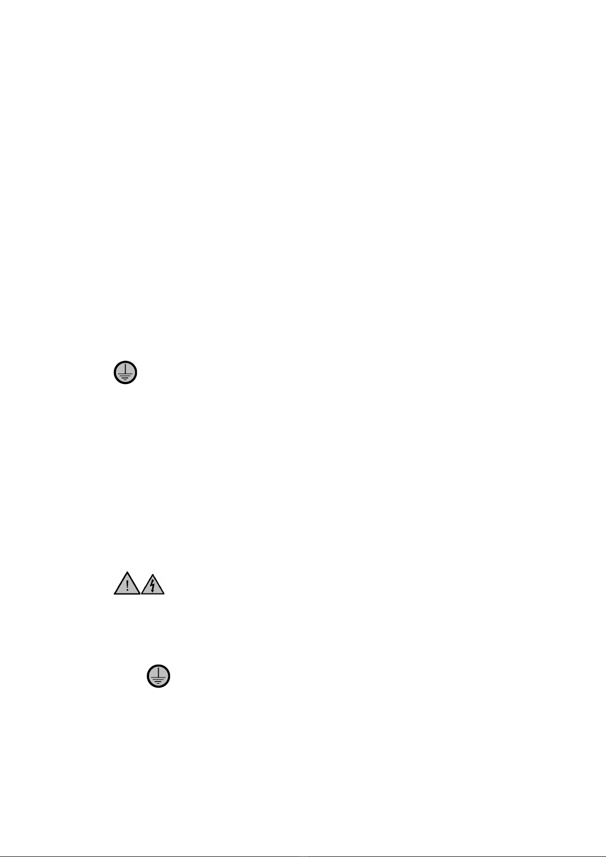
2.2. Symbols defined.
Caution, risk of danger. See note
or adjacent symbol.
This symbol denotes the use of the
heating function
Protective conductor terminal to
be earthed. (Do not loosen or
disconnect).
This symbol denotes this section of
the fascia is designated for the control
of the stirring function.
Caution / risk of electric shock
This symbol denotes this section of
the facia is designated for the setting
and control of the temperature
Recyclable Packing Material
These symbols are designated for the
left and right arrow functions when
setting the product
Do not dispose of product in
normal domestic waste.
These symbols are designated for the
up and down arrow functions when
setting the product
Caution. Hot surface.
Bio Chemical Hazard. Caution
required. Will require
decontamination.
Refer to Instruction book.

Page 5 of 24
RS1000 Instruction Book M7239. Issue 4.3
3.
SAFETY INFORMATION.
This product has been designed for safe operation when used as detailed in accordance with the
Manufacturer’s instructions.
NOTE: Failure to use this equipment in accordance with the manufactures operating instructions
may compromise your basic safety protection afforded by the equipment and may invalidate the
warranty / guarantee. The warranty / guarantee does not cover damaged caused by faulty
installation or misuse of the equipment
3.1. Prevention of Fire and Electric Shock.
To prevent a risk of fire or electric shock,
DO NOT
open your product case
without authorisation. Only Qualified Service Personnel should attempt to
repair this product.
Replace fuses only with the type as listed in section, ‘Technical
Specifications and Parts and Accessories’ (See fuse type and rating).
Ensure the Mains Power Supply conforms to rating found on the data plate
located on the right hand side of this product.
Never
Operate this equipment without connection to earth / ground.
Ensure the mains supply voltage is correctly earthed / grounded in
accordance with current area legislation.
3.2. General Safe Operating Practice.
Always follow good laboratory practice when using this equipment. Give
due recognition to your company’s safety and legislative health & safety
procedures and all associated legislation applicable to your areas of
operation. Check laboratory procedures for substances being heated and
ensure all hazards (e.g. explosion, implosion or the release of toxic or
flammable gases) that might arise have been suitably addressed before
proceeding. When heating certain substances the liberation of hazardous
gases may require the use of a fume cupboard or other means of
extraction.
Do not
position the product so that it is difficult to disconnect from the
mains supply.
Do not touch the heating block or any glass vessel whilst in use.
Do not lean or stretch over equipment, glassware and fixings when in use.
Do not immerse unit in water or fluids.
Do not spill substances onto the heating block. If spillage does occur,
disconnect unit from mains supply and follow instructions as detailed in

Page 6 of 24
RS1000 Instruction Book M7239. Issue 4.3
Maintenance. (Section 9).
Do not cover this product whilst in use. Do not block or obstruct ventilation
slots / airways.
Do not leave equipment switched on without a charged flask(s).
It is not recommended to leave any heating apparatus unattended during
operation.
Only use Original Equipment manufacturers spares and accessories. Ref
Section 10.
This equipment will generate magnet fields. Keep all metal objects and
magnetic data devices (e.g. credit cards) away from the stirrer unit.
The equipment is not spark, flame or explosion proof and has not been
designed for use in hazardous areas in terms of BSEN 60079-14:1997.
Keep flammable, low flash point substances away from the apparatus.
Do not operate or handle any part of the product with wet hands.
Keep the Mains cord and moulded IEC plug and lead set away from the
heating surface.
Page 7 of 24
RS1000 Instruction Book M7239. Issue 4.3
4.
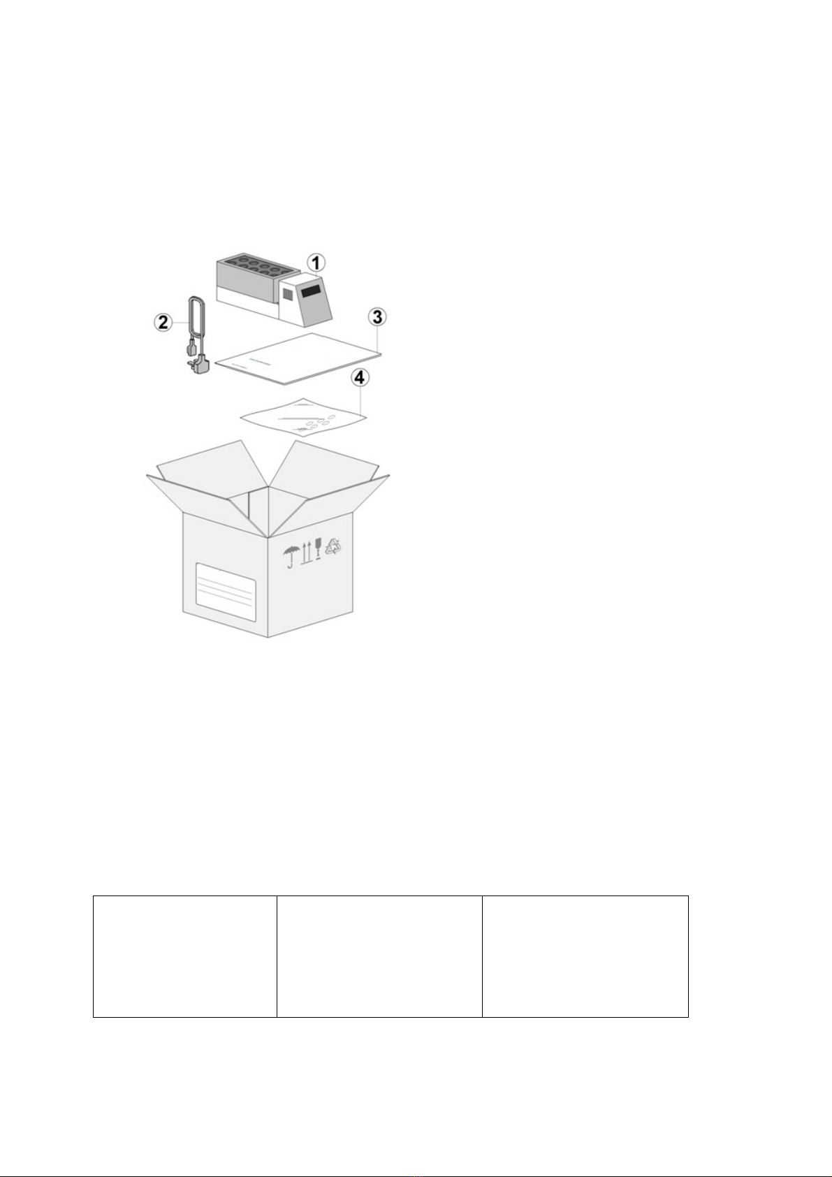
UNPACKING AND CONTENTS.
4.1. Please check the contents of your carton against the diagram.
Item Description Qty
1 RS1000 Product 1
2 Mains Cord and Lead set A/R
(illustration only)
3 Instruction book 1
4 Stir Bars (Pkt 10) 1
For future reference
please record your
products Serial and
Model Numbers.
Serial Number Unit Model/Cat Number
Page 8 of 24
RS1000 Instruction Book M7239. Issue 4.3
5.
INSTALLATION.
5.1.
Electrical safety and installation.
5.1.1.
This equipment is designed to be used safely under the following conditions:-
•Indoor use.
•Altitude up to 2000 meters.
•Temperatures between 5°C and 40°C.
•Maximum relative humidity 80% for temperatures up to 31°C decreasing linearly to
50% relative humidity at 40°C.
•Mains supply voltage fluctuations up to ±10% of the nominal voltage.
•Transient over voltages typically present on the mains supply
(Over voltage category II). Applicable rated pollution degree 2.
5.2.
This equipment must be earthed / grounded to a fixed earth / grounded mains
socket outlet. The mains supply is to earthed / grounded in accordance with current
legislation.
5.3.
Ensure only the correct rated mains input fuses are fitted. (Where applicable ensure the
correct Mains cord and moulded IEC plug and lead set fuse if fitted). See Technical
Specification Section 8 of this Instruction book.
5.4.
Check the voltage on the data label of this product. Ensure the rating conforms to your
local supply.
5.5.
It is recommended this product be connected to a mains supply source which
incorporated a RCD or GFCI device.
5.6.
Do not install this product or accessories on a surface which may become
wet or flooded.
5.7.
The unit is supplied with a Mains cord and moulded IEC plug and lead set wired as
follows.
Green / Yellow
or Green = Earth / Ground
Blue or White = Neutral
Brown or Black = Live / line hot.

Page 9 of 24
RS1000 Instruction Book M7239. Issue 4.3
5.8.
Install equipment is used on a clean, dry, non-combustible, solid work surface
with at least 300mm suitable clearance all around from other equipment / objects.
6.
ENVIRONMENTAL PROTECTION.
6.1.
Maximum consideration has been given to environmental issues within the design and
manufacturing process without compromising end product performance and value.
6.2.
Packaging materials have been selected such that they may be sorted for
recycling.
6.3.
At the end of your product and accessories life, it must not be discarded as
domestic waste. Ref: EU Directive 2002/96/EC on Waste Electrical and Electronic
Equipment Directive (WEEE). Please contact your distributor / supplier for further
information. For end users outside of the EU consult applicable regulations.
6.4.
This product should only be dismantled for recycling by an authorised recycling
company.
This product and accessories must be accompanied by a completed
Decontamination Certificate prior to any disposal. Copies of the Certificate are
available from your distributor of Bibby Scientific products, or you may copy and
enlarge from ‘Appendix A’ of this instruction book.
Page 10 of 24
RS1000 Instruction Book M7239. Issue 4.3
Bibby Scientific’s Electrothermal branded product range is registered with the Environment Agency under the name of as Electrothermal
Engineering Limited as being a producer of WEEE (Waste Electronic and Electrical Equipment) through b2b Compliance,an authorised waste
collection compliance scheme.
7.
PRODUCT OPERATION.
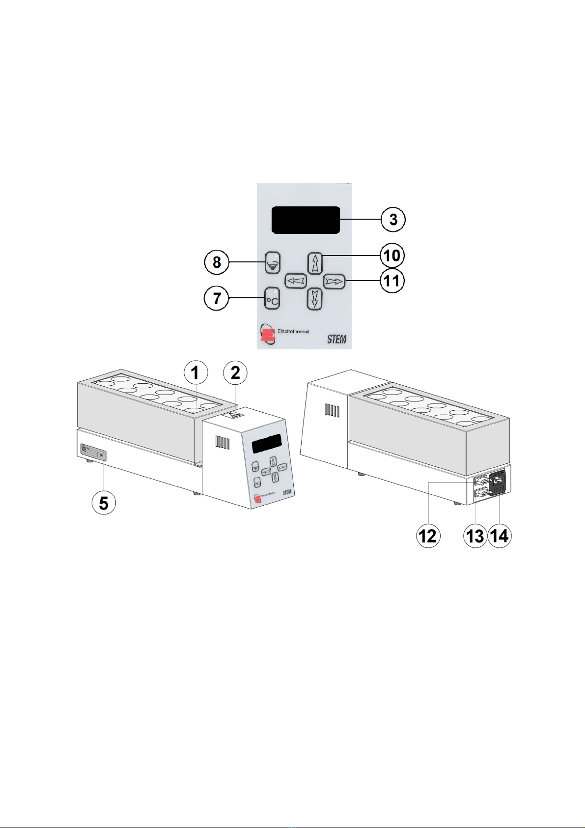
7.1. The illustration below shows the general layout of the RS1000.
1 Reaction block chamber
2 Hot Surface warning Label.
3 Display
5 Data Plate – Refer to for correct voltage.
7 Temperature on/off selection button
8 Stir facility on/off button
10 Up / Down arrow function select and set button
11 Left / Right arrow function select and set button
12 RS232 9-way connection socket.
13 RS485 9-way connection socket
14 IEC socket with fuse protection.

Page 11 of 24
RS1000 Instruction Book M7239. Issue 4.3
7.2. Plug the mains cord with the moulded IEC plug into the IEC socket of the unit. Connect the
mains plug to the correct voltage mains supply. Check data plate for correct voltage
input.
7.3. The display will peform a warm up and self check prior to displaying the present temperature
for the reaction block.
Sound Indication: - A short ‘Beep’ gives indication of parameter change. Long ‘Beep’ gives
warning of error.
7.4. Main Screen
7.4.1.The following screen shot shows the actual block temperature. This is likely to be at
ambient temperature when the RS1000 is first powered up from cold. The “T” in the
display shows the mode for setting the temperature. The “S” in the display shows the
mode for setting the stir speed. The “t” in the display is used to set the count down time
left before the heating function is turned off. Actual block temperature is displayed in
degrees Centigrade. Stir speed is measured in RPM and shown with the “s” symbol
denoting Speed.
Note: If 10 seconds elapse without a key being pressed the display is to return to the
main display screen.
7.5. Setting and Operating the Heater Function
7.5.1.From the main display screen press the < key to go into Temp setting screen.
7.5.2.Press the ^or vto make the 100’s selection. Press the >key to go into 10’s set screen.
First time factory default setting to be 5
°
C.
Last user setting will be displayed.
Page 12 of 24
RS1000 Instruction Book M7239. Issue 4.3
7.5.3.Press the ^or vto make the units selection. Press the >to go back to main display
screen.
7.5.4.To commence heating press the heating button. To turn off the heating function press
the button one once again.
Note: The main display screen will always show the actual temperature of probe or block
PT100. During the heating process the red LED found in the center of the Heater on/off key
will flash. When the set temperature has been reached the flashing will stop and remain
constantly illuminated.
When adjusting the set temperature from a reached temperature to another, to accommodate
over / under temperature oscillation the LED will not recommence flashing until temperature
of ± 10°C off of the original set temperature has been made.
7.6. Stirrer Functions.
7.6.1. From the Main display screen press the > key to enter the Stir speed selection screen.
7.6.2.Press the > or < to make the 1000’ 100’ 10 and units selection. Press the ^ and v
buttons to select the values.
Note: The maximum settable stir speed value is 2000 rpm.
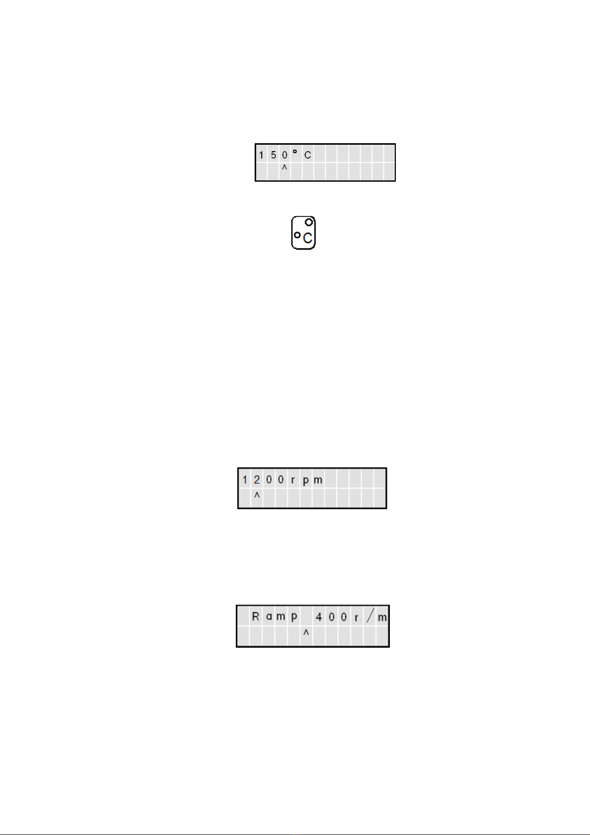
7.6.3.Press the > from the units setting to enter the stir speed ramp mode.
7.6.4.Using the > or < to make the 1000’ 100’ 10 and units selection. Press the ^ and v
buttons to select the ramp speed values.
Example: in the example, the stir speed will ramp up at the rate of 400rpm per minute. So if a
stir speed of 1200 rpm was set, it would take approximately 2 minutes to ramp from start to
1200rpm. Ie 400 to 1200 rpm in 2 minutes.
7.6.5. Repeatedly press the > button to exit the stir speed setting mode.
7.6.6. To commence stirring press the stir button. To stop stirring press the stir button once
again.

Page 13 of 24
RS1000 Instruction Book M7239. Issue 4.3
7.7. Timer set function.
The maximum time setting is 99 hours and 59 minutes.
Note: Once the timer has been set it will not commence count down until the Heater on/off
key is activated.
7.7.1.From the main display screen press the ^ key.
7.7.2.Press the ^or vto make the 10’s hours selection. Press the >key to go into unit hours
selection screen.
7.7.3. Press the ^or vto make the 10’s minutes selection. Press the >to go back to main
display screen.
Note: If 10 seconds elapse without a key being pressed the display is to return to the
main display screen.
7.7.4.With the timer set the front screen will display only count down hours until only minutes
are left on the time counter, then minutes are to be displayed. The front screens will
look like this. hdenotes hours and mdenotes minutes. When the time counter reaches
zero the heaters are turned off. The Heater on Red LED is extinguished and the main
display screen reverts to ^t. A 1 second beep is to be sounded when heaters are turned
off in timer mode.
Note: The timer will not commence count down until the set temperature has been
reached and the Red LED is constant.

Page 14 of 24
RS1000 Instruction Book M7239. Issue 4.3
7.8. Host PC Operation.
7.8.1.Disconnect the power to the unit.
7.8.2. Connect a lead between the host PC and the RS232 socket of the RS1000 unit.
7.8.3.When the unit is coupled to external software that is PC biased, the keypad will become
locked and access to the RS1000 menu will not be possible.
7.9. RS232 Operation.
7.9.1.When the unit is coupled to an external host robotic system that is either RS485 or
using GSIOC protocol through the RS485 socket the following screens are seen.

Page 15 of 24
RS1000 Instruction Book M7239. Issue 4.3
7.10. STEM
Protocol (RS232).
Stem command SET can be operated using RS232.
Unit address 40. Baud rate is 9600, N, 8, 1.
Command set as follows: -
LK*
Local Keypad (0 or 1)
SE
*
Stirrer enabled (0 or 1)
SR
*
Stir speed ramp rate (400 to 2000 per min)
SS
*
Stir Speed (RPM) (400 to 2000)
TE
*
Thermal control enabled (0 or 1)
TT*
Target temperature. (ºC). (0.0 to 150)
TR
*
Temperature Ramp rate (ºC/min) (0.0 to 5.0)
Note: For TR 0.0 indicates no control. *Denotes variable parameter
Query command set
QC
Request commanded variables
QF
Request system principal fixed values.
QM
Request measured data
Using a suitable terminal, type in and test some of the commands and query set,
STEM protocol.
Examples of STEM Command protocol used.
“<CR>” Is a carriage return character.
Type in: >40 SE1 #0000 <CR>
Response: <40.00 OK <CR>
Result: Stirrer enabled (LED for stirrer ON< RS600 will commence stirring).
Type in: >40 SE0 #0000 <CR>
Response: <40.00 OK <CR>
Result: Stirrer disabled (LED for stirrer OFF, RS600 will stop stirring).
Type in: >40 TT123,4 TE1 #0000
Response >40,00 OK <CR>
Result Target temperature set to 123, 4ºC, thermal control enabled (LED for
ON< temperature will begin to raise block temperature).
Type in: >40 SS2000 SE1 SR2 #0000 <CR>
Response: <40,00 OK <CR>
Result: Stirring enabled, stirring speed set to 2000 rev/min, Stirrer ramp rate
set to 2, (Stirring speed will steadily increase to 2000 rev/ min over 2
minutes).

Page 16 of 24
RS1000 Instruction Book M7239. Issue 4.3
GSIOC Interface module for RS1000.
The interface module is designed to comply with the specifications in the Gilson
document “GSIOC technical Manual” dated March 1999.
Buffered Commands:
Command Meaning.
T1 Turn on thermal control
T0 Turn off thermal control
S1 Turn on stirrer, start speed ramp-up
S0 Turn off stirrer, reset speed ramp.
P# Set temperature set point to #°C (Range 5 to 150°C)
V# Set stir speed target to # rpm (Range 400 to 2000)
R# Set stir ramp control to # rpm/min (Range 0 to 2000 – 0 means no
ramp control).
L1 Lock local keypad
L2 Unlock local keypad
Z# Set GSIOC address
Immediate commands
Command Meaning. Return Value.
$ Reset unit $
W Report current temperature # (# is temperature in °C).
Q Report set temperature set
point
# (# is set point in °C).
A Report for stir speed # (# is set speed in rpm).
B Report set ramp time # (# is set ramp time in seconds).
S Report status xy X is the ‘ready’ status; it will be “1”
if the unit is not ready to accept a
command and “0” if the unit is
ready. Y is the ‘error’ status; it will
be “12 if the last command was
not accepted, otherwise it will be
“0”
K Report keypad lock status x X is “1” for locked, and “0” for not
locked.
Notes:
•Before taking control of the unit using GSIOC, the ‘L1’ command must be sent to lock the local keypad.
When control is released, ‘L0’ may be sent to unlock the keypad and allow manual control.

Page 17 of 24
RS1000 Instruction Book M7239. Issue 4.3
•Numbers, represented by “#” are decimal numbers of up to four digits.
8.
TECHNICAL SPECIFICATIONS.
8.1. Specification.
Mains Supply Power. 230V-AC or 115/100V-AC @ 50/60Hz
Mains Power Lead set (UK) 13A
BS1362
3 core earthed / ground. 2 meters long
Moulded IEC plug and Lead set – supply cord H0 V V-F-
Replace only with equivalent cable.
Mains Power Lead set (Europe) 3 core earthed / ground. 2 meters long
Moulded IEC plug and Lead set – supply cord H0 V V-F-
Replace only with equivalent cable.
Mains Power Lead set (USA) 3 core earthed / ground. 2 meters long
Moulded IEC plug and Lead set – supply cord SJT VW
1- Replace only with equivalent cable.
Lead set plug fuse (UK – only) 13A
Power Consumption 600W
Operating Ambient Temperature 5°C to 40°C
Heating Temperature Range Ambient + 5 to 150°C
Display 2 x 12 back lit LED.
Fuse Type and Rating 230V~AC F5A Quick Blow 20mm
115 / 100V ~ AC F8A Quick Blow 20mm
Number of Vessel positions 10
Vessel diameter 24 / 25mm – may be reduced by the use of optional
adapter sleeves.
Well diameter 24.5 / 25.5mm
Stirring Rate Off and variable 400 to 2000 RPM.
Stirring speed accuracy ±0.5%.
Temperature stability ±1.0°C (Still air, under no load condition).
Interface RS232, RS485
Connection 9-way ‘D’ type socket / plug for connection to the serial
port of a laboratory computer or liquid handling system.
8.2. The Ingress protection rating for this product is classified as IPX1.

Page 18 of 24
RS1000 Instruction Book M7239. Issue 4.3
8.3. Weight. 4.0Kg without Glassware a Mains Cable.
8.4. Emissions Classification. (115V Only).
Warning! Any modification or changes made to this device, unless explicitly approved by
Bibby Scientific Limited, will invalidate the authorisation of this device. Operation of an
unauthorised device is prohibited under Section 302 of the Communications Act of 1934 as
amended, and Subpart 1 of Part 2 of Chapter 47 of the code of Federal Regulations.
NOTE: This equipment has been tested and found to comply with the limits for a Class A
digital device, pursuant to part 15 of the FCC Rules. These limits are designed to provide
reasonable protection against harmful interference when the equipment is operated in a
commercial environment. This equipment generates uses and can radiate radio frequency
energy and, if not installed and used in accordance with the instructions, may cause harmful
interference to radio communications. Operation of this equipment in a residential area is
likely to cause harmful interference in which case the user will be required to correct the
interference at their expense.
NOTE: (230V) Product is found to comply with the limits of Class B digital device, pursuant to
part 15 of the FCC Rules.
Guidance notes.
Class A Digital Device.“A digital device that is marketed for use in a commercial, industrial
or business environment, exclusive of a device which is marketed for use by the general
public or is intended to be used in the home.”
Class B Digital Device.“A digital device that is marketed for use in a residential environment
notwithstanding use in commercial, business and industrial environments. Examples of such
devices included, but are not limited to, personal computers, calculators, and similar
electronics devices that are marketed for use by the general public

Page 19 of 24
RS1000 Instruction Book M7239. Issue 4.3
9.
MAINTENANCE.
9.1. General Information.
Unplug the unit from the mains voltage supply and allow it to cool before
undertaking any maintenance tasks.
Maintenance should only be carried out under the direction of the Responsible
Body, by a competent electrician. Failure to do so may result in damage to the product
and in extreme cases be a danger to the end user.
With proper care in operation this equipment has been designed to give many years of
reliable service. Contamination or general misuse will reduce the effective life of this product
and may cause a hazard.
Maintenance for the unit should include:
•Periodic electrical safety testing (an annual test is recommended as the minimum
requirement).
•Regular inspection for damage with particular attention to the mains lead and plug
set.
•Routine cleaning of the equipment should be undertaken using a clean cloth.
DO NOT USE SOLVENTS FOR CLEANING ANY PART OF THIS EQUIPMENT.
9.2. Internal Fuse Replacement.
The mains fuse holder is located at rear your product. Refer to Technical Specification, ‘Fuse
Rating’ for correct fuse type and rating. Turn your product off and remove it from the mains
supply. Open fuse draw and remove fuses. Fit replacement fuses and close the draw.

Page 20 of 24
RS1000 Instruction Book M7239. Issue 4.3
9.3. Servicing.
This product should be serviced by a Bibby Scientific Service Engineer or by an agent on
behalf of the manufacturer. If in doubt contact Customer Support. See Section 10.
9.4. Spillage and Decontamination.
In the event of spillage switch off and unplug this product from the mains electrical supply.
Wipe off all excess liquid from the reaction block and surrounding area using an absorbent
soft cloth. Allow sufficient time for any ingressed liquid to evaporate before commencing with
use.
If in doubt please consult Customer Support. Refer to section 10.
If the equipment has been exposed to contamination, the Responsible Body
is responsible for carrying out appropriate decontamination. If hazardous material has
been spilt on or inside the equipment, decontamination should only be undertaken
under the control of the Responsible Body with due recognition of possible hazards.
Before using any cleaning or decontamination method, the Responsible Body should
check with the manufacturer the proposed method will not damage the equipment.
Prior to further use, the Responsible Body shall check the electrical safety of the unit.
Only if all safety requirements are met can the unit be used again. The above
procedure is intended as a guide. Should spillage occur with a toxic or hazardous
fluid then special precautions may be necessary.
Decontamination Certificate.
Note: In the event of this equipment or any part of the unit becoming damaged, or requiring
service, the item(s) should be returned to the manufacturer for repair accompanied by a
decontamination certificate. Copies of the Certificate are available from
Distributor/Manufacturer. Appendix A of this instructions book may be copied and
enlarged.
At the end of life, this product must be accompanied by a Decontamination Certificate.
See section 6.3 and 6.4
Other Electrothermal Laboratory Equipment manuals


Popular Laboratory Equipment manuals by other brands

W&H Med
W&H Med lyla RIN-210-17 Instructions for use

Optika Italy
Optika Italy ACCESSORIES Series instruction manual

Velp Scientifica
Velp Scientifica RX3 instruction manual

Tableau
Tableau TX1 user guide

Pall
Pall Minimate EVO TFF quick start guide

Diesse
Diesse CHORUS TRIO CHORUS EXPANDER UPGRADE KIT installation guide


