Electrothermal INTEGRITY 10 User manual
Page 1 of 80 M8024 Issue 3.4 For use with master product
software V3.5.1.8 and above.
(Integrity 10 Reaction Station & Power Supply unit).
INTEGRITY 10. REACTION STATION.
PS20000
INSTRUCTION BOOK

Page 2 of 80 M8024 Issue 3.4 For use with master product
software V3.5.1.8 and above.
Please take your time to read this Instructions book in order to understand the safe and
correct use of your new Bibby Scientific product.
It is recommended the Responsible Body for use of this equipment reads this Instruction
book and ensures the user(s) are suitably trained in its operation.
Section 1.
Introduction.
Page 4
Section 2.
Symbols and using this Instruction Book.
Page 5
Section 3.
Safety Information.
Page 6
Section 4.
Unpack and Contents.
Page 9
Section 5.
Installation.
Page 10
Section 6.
Environmental Protection.
Page 12
Section 7.
Product Operation.
Page 13
7.1
Product Overview
Page 13
7.2
Reduction Sleeves, Fitting Removal
Page 14
7.3
Insert SD Card
Page 15
7.4
Turn Unit On
Page 16
7.5
Turn Unit Off
Page 16
7.6
Splash Screen
Page 16
7.7
Clock and Date settings
Page 17
7.8
Communication Protocol Selection
Page 19
7.9
View Firmware Release Set
Page 20
7.10
Manual Control
Page 20
7.11
Profile Control
Page 27
7.12
Name and Storing a Profile
Page 37
7.13
Stored Profile View and Copy
Page 42
7.14
Saving an Experiment
Page 46
7.15
Reviewing Stored Experiment Data
Page 50
7.16
Outputting Stored Data via USB Flash Drive
Page 53
7.17
Control by Contents
Page 54
7.18
External Control.
Page 56
Section 8.
Technical Specifications.
Page 57
Section 9.
Maintenance, Service and Customer Repair.
Page 64
9.1
General Information
Page 64
9.2
Spillage Procedure
Page 65
9.3
Decontamination
Page 65
9.4
Cell Replacement
Page 66
9.5
Cell flash update
Page 71
9.6
Error and Warning Messages.
Page 72
Section 10.
Customer Support.
Page 76
Section 11.
Parts and Accessories.
Page 77
Section 12.
EC Declaration of Conformity
Page 80
Appendix ‘A’
Decontamination Certificate
Page 79

Page 3 of 80 M8024 Issue 3.4 For use with master product
software V3.5.1.8 and above.
©The copyright of this instruction book is the property of Bibby Scientific Limited. This instruction book is supplied by
Bibby Scientific Limited on the express understanding that it is to be used solely for the purpose for which it is supplied. It
may not be copied, used or disclosed to others in whole or part for any purpose except as authorised in writing by Bibby
Scientific Limited. Bibby Scientific Limited reserves the right to alter, change or modify this document without prior
notification.
In the interest of continued development Bibby Scientific Limited reserve the right to alter or modify the
design and /or assembly process of their products without prior notification.
This product is manufactured in Great Britian by Electrothermal, part of the Bibby Scientific Group of companies.
Bibby Scientific Limited.
Beacon Road,
Stone,
Staffordshire ST15 0SA,
Great Britain.
Tel: +44(0)1785 812121
Fax: +44(0)1785 810405

Page 4 of 80 M8024 Issue 3.4 For use with master product
software V3.5.1.8 and above.
1. INTRODUCTION.
1.1. The Integrity 10 Reaction Station’s evolutionary design provides the advanced laboratory with a means for
allowing the users to perform multiple reactions at individually set temperatures both in negative and
positive temperature ranges simultaneously. Each cell position can be heated / cooled and stirred
independently of the cell next to or adjacent to it.
1.2. The versatility of the product means it can be used inside a fume cupboard, mounted into a robotic platform,
coupled together as multiple units for mass multi-sampling or simply operated free standing on a laboratory
work surface. For user safety, low voltage power supplied by the PSU (Power Supply Unit) drives the
Integrity 10. An Ethernet socket provides a means for connecting and controlling the Integrity 10 as part of
an integrated system. RS485 / 232 and GSIOC protocol all add up to make this product perhaps the most
versatile in the market to date.
1.3. Advanced ‘STEM Integrity’ control software available as an accessory augments the versatility of the
product by providing the user with a ‘simple to use’ user friendly, intuitive interface.
1.4. When used with ‘STEM Integrity’ software additional accessories can be added to customise the Integrity 10
specifically for given tasks such as, infrared probes for superior measurement of particles present in any
given solution. Solution sample temperatures in each cell position can be accurately measured using the
Electrothermal ‘Multitemp’ probe set. In addition, PH Probe, Over Head Stirrer and Dossing pumps can all
be added to further enhance your system. The system is completed with a Reflux unit designed to prevent
fluid sample solution losses from open, exposed glass vessels / test tubes. (See accessories or refer to
customer support).
1.5. For standalone use the Integrity 10 is easy to set up using the touch screen. With an intuitive menu system,
operation is both quick and simple allowing the user to set up and operate a simple profile or operate with
full manual control. Furthermore, experiment data can be stored and extracted via a USB flash key. The
look and feel of the menu is akin to that of the ‘STEM Integrity’ application software thus making the
transition from one to another a simple formality. The operating system is MicrosoftWindows CE.
Firmware is stored on the SD card supplied. For new firmware releases simply insert the new SD card.
1.6. The Integrity 10 has the facility to:
Start all cell positions individually or all 10 positions simultaneously.
Input start temperature, ramp rate, dwell time and temperature and decrease ramp rate and final
temperature coupled with stir speed all from one screen using the on screen keyboard.
Name and record an experiment for future referral with information stored for the experiment as entered
by the chemist which may then be extracted using USB flash key.
1.7. Each cell position is heated from a cartridge heater and cooled by a Peltier device, operated from 15 Volts
supplied from the PSU. Connection to an external recirculation coolant system provides a minimum
temperature of -30C, (with coolant at 5C or less). The maximum temperature is +150C.
1.8. Stirring is achieved using a rotating magnet principal with magnetic flux coupling. The Integrity 10 can stir
solution from 350RPM to 1200RPM.
Page 5 of 80 M8024 Issue 3.4 For use with master product
software V3.5.1.8 and above.
2. SYMBOLS AND USING THIS INSTRUCTION BOOK.
2.1. Throughout this Instructions book the following symbols are shown which identify conditions that pose a
hazard to the user or to identify actions that should be observed. These symbols are also shown on the
product or its packaging. When a symbol is shown next to a paragraph or statement it is recommended the
user takes particular note of that instruction in order to prevent damage to the equipment or to prevent injury
to one’s self and other people.
The Responsible Body and the Operator should read and be familiar with this Instructions book in
order preserve the protection afforded by the equipment.
To prevent injury or equipment damage it is the manufacturer’s recommendation that all persons
using this equipment are suitably trained before use.
2.2. Symbols defined.
Caution, risk of danger. See note or adjacent
symbol.
Protective conductor terminal to be earthed.
(Do not loosen or disconnect).
Caution / risk of electric shock
Recyclable Packing Material
Do not dispose of product in normal domestic
waste.
Caution. Hot surface.
Bio Chemical Hazard. Caution required. Will require
decontamination.
Contains CR2032 button coin battery.
(To be disposed of according to regulations- not
customer serviceable).
Refer to this Instructions book
Port communication symbol.
Cooling fluid. Connect inlet supply to Left hand side
connector.
Cooling fluid. Connect outlet supply to Right hand
side connector.
Hot / Cold Zone. Avoid contact
inside the well.

Page 6 of 80 M8024 Issue 3.4 For use with master product
software V3.5.1.8 and above.
3. SAFETY INFORMATION.
This product has been designed for safe operation when used as detailed in accordance with the Manufacturer’s
instructions.
NOTE: Failure to use this equipment in accordance with the manufactures operating instructions may
compromise your basic safety protection afforded by the equipment and may invalidate the warranty / guarantee.
The warranty / guarantee does not cover damaged caused by faulty installation or misuse of the equipment.
3.1. Prevention of Fire and Electric Shock.
To prevent a risk of fire or electric shock, DO NOT open the Integrity PSU case without
authorisation. Only qualified Service personnel should attempt to repair / service the PSU.
Ensure the Mains Power Supply conforms to rating found on the data plate located on the
underside of the PSU.
Never Operate this equipment without connection to earth / ground. Ensure the mains supply
voltage is correctly earthed / grounded in accordance with current area legislation.
3.2. General Safe Operating Practice.
Always follow good laboratory practice when using this equipment. Give due recognition to
your company’s safety and legislative health & safety procedures and all associated
legislation applicable to your areas of operation. Check laboratory procedures for substances
being heated and ensure all hazards (e.g. explosion, implosion or the release of toxic or
flammable gases) that might arise have been suitably addressed before proceeding. When
heating certain substances the liberation of hazardous gases may require the use of a fume
cupboard or other means of extraction. (Consult your company practice).
Ensure equipment is used on a clean, dry, non-combustible, solid work surface with at least
300mm suitable clearance all around from other equipment.
Ensure the PSU is positioned on a clean, dry, non-combustible surface with a sufficient space
for the power cable to Integrity 10 and mains input lead and plug set to enter / exit without
undue bend stresses. Ensure a suitable clearance for air flow and heat dissipation.
Do not position the Integrity 10 or Power Supply Unit so that it is difficult to connect /
disconnect from the power cable assembly.
Do not position the Integrity 10 or Power Supply Unit so that it is difficult to connect /
disconnect from the coolant fluid supply.
Do not position the Integrity 10 or Power Supply Unit so that it is difficult to connect /
disconnect data and communication cables.
Do not position the PSU so that the on / off switch or IEC mains socket located on the rear is
inaccessible.
Do not immerse any part of this equipment in water / fluid.
Do not spill substances on the touch screen. Case materials are protected as defined in the
table 8.1 Chemical resistance chart. If spillage does occur, disconnect unit from mains supply
and follow instructions as detailed in Section ‘Maintenance, Service and Customer Repair’.
Do not cover the Integrity 10 or PSU (ESPECIALLY VENTILATION SLOTS) whilst in use.
It is not recommended to leave any heating apparatus unattended during operation.
Only use Original Equipment Manufacture’s Parts and Accessories. Ref Section 11.
The equipment is not spark, flame or explosion proof and has not been designed for use in
hazardous areas in terms of BSEN 60079-14:1997. Keep flammable, low flash point
substances away from the apparatus.
Do not operate or handle any part of this product with wet hands.
Page 7 of 80 M8024 Issue 3.4 For use with master product
software V3.5.1.8 and above.
Do not touch the inside of the cells when the product is in operation.
Take care when handling HOT & COLD glassware
Do not lean or stretch over the unit when in operation.
Keep the Mains Plug and Lead set cable away from the heating surface.
Touch Screen Warning. The screen is impervious to Acetone. It is recommended that any
chemical spillage is wiped off the screen immediately.
Warning: Standard glassware supplied for the Integrity product is not designed for high
pressure applications. Maximum operating pressure of standard glassware with Inerting cap
fitted is 0.5bar.
ATS10075
24mm
diameter
Glassware
Borosilicate glass, 1.6mm wall thickness. General glassware is not pressure tested.
Warning: Glass vessels can explode or implode violently, either spontaneously from stress
failure caused by pressure or vacuum, or from accidental impact.
Carefully check glass vessels for star cracks, scratches or etching marks before each use.
Cracks can increase the likelihood of breakage or may allow chemicals to leak into the
equipment.
Conduct all pressure and vacuum operations in glass vessels behind adequate shielding and
use Personnel Protective Equipment (Full face guard, gloves, protective clothing) during
handling.
Risk assessment is required by user to ensure adequate safety precautions / use of, screens
, hoods, PPI etc. for process being operated with due regard to use of glassware at
pressures other than atmospheric.
Test undertaken by Electrothermal Engineering on sample new glassware at ambient
temperature, assembled with ATS10377 inerting cap, (tested under water) indicate withstand
pressure of 0.5 bar gauge.
When intering cap is fitted, the septum cap can acts as a pressure relief valve which can
open suddenly and blow out (with some velocity) at pressures over 2 bar gauge. (NB:
Sampling probes inserted through Septum cap may restrict this pressure relief action.)
Risk assessment is required by end user to ensure adequate safety precautions / use of,
screens , hoods, Personal Protective Equipment etc. for process being operated with
glassware at pressures other than atmospheric.
Warning: When inerting cap is fitted, the septum cap can acts as a pressure relief valve which
can open suddenly and blow out (with some velocity) at pressures approaching 2 bar gauge.
(NB: Sampling probes inserted through Septum cap may restrict this pressure relief action.)
For high pressure applications, please contact Bibby Scientific Help
Additional
pressure safety
information.
ATS10377
Inerting Cap
See below
Viton (main seal
and o rings)
Viton is resistant to a wide range of chemicals including oils, aqueous media and most
other fluids. Recommend check for specific chemicals by reference to internet search
engine. Numerous web sites give data on Viton chemical resistance.
http://www.dupontelastomers.com/Products/Viton/viton.asp
PFTE Cap and
valve spindle
PTFE is resistant to a wide range of chemicals, including ozone, chlorine, acetic acid,
ammonia sulphuric acid and hydrochloric acid. The only chemicals known to affect these
coatings are molten alkali metals and highly reactive fluorinating agents.
Recommend check for specific chemicals by reference to internet search engine.
http://www2.dupont.com/Teflon_Industrial/en_US/tech_info/prodinfo_ptfe.html

Page 8 of 80 M8024 Issue 3.4 For use with master product
software V3.5.1.8 and above.
Silicone Cap
Septum
Peroxide cross linked HTV silicone rubber, classified in accordance with ASTM D 1418 as
VMQ.
Recommend check for specific chemicals by reference to internet search engine
316 Stainless Steel
gas nozzle
Recommend check for specific chemicals by reference to internet search engine.
316 Stainless steel
2mm dia sampling
hole bung
Recommend check for specific chemicals by reference to internet search engine.

Page 9 of 80 M8024 Issue 3.4 For use with master product
software V3.5.1.8 and above.
4. UNPACK AND CONTENTS.
4.1. Please check the contents of your carton against the diagram.
PLEASE NOTE THIS ISSUE PRODUCT CONTAINS RS232 POWERED COMMUNICATION CABLE FOR
USE WITH RSPC CONTROL SOFTWARE. PLEASE SEE SECTION 5.10.
For your future reference
please record your products
Serial and Model numbers.
PS20000 Unit Serial Number
PS20000 Unit Model/Cat Number.
PS20000 PSU Serial Number
PS20000 PSU Model/Cat Number
Item
Description
Qty
1
Instruction book
1
2
Integrity 10 - PSU
1
3
Integrity 10 - UNIT
1
4
Mains cord and lead set
(illustration only)
A/R
5
Stir bars (Pkt10)
1
6
Power cable assembly
(illustration only)
1
7
Coolant supply hoses
2
8
Programmed SD card –
Pre inserted in the unit.
1

Page 10 of 80 M8024 Issue 3.4 For use with master product
software V3.5.1.8 and above.
5. INSTALLATION.
5.1. Electrical safety and installation.
5.1.1.1. This equipment is designed to use safely under the following conditions:-
Indoor use.
Altitude up to 2000 meters.
Temperatures between 5C and 35C.
Maximum relative humidity 80% for temperatures up to 25C decreasing linearly to 50% relative
humidity at 35C.
Mains supply voltage fluctuations up to 10% of the nominal voltage.
Transient overvoltages typically present on the mains supply. (Overvoltage category II)
Applicable rated pollution degree 2.
The Power Supply Unit (PSU) for the Integrity 10 has been subjected to electrical safety testing as part of
the manufacturing process. However, it is acknowledged that some end users may wish to undertake further
electrical safety testing as part of the installation process.
AC dielectric withstand (Flash / Hi Pot) must not be undertaken on this equipment as damage
may result. Such testing will invalidate warranty.
DC dielectric withstand (flash / Hi Pot) may be applied to the PSU only (i.e. The Integrity 10 unit must not
be connected when the PSU is being tested. The Integrity 10 unit operates at low voltage (15V DC) and
must not be subjected to dielectric withstand (Flash / Hi Pot) testing.
DC dielectric withstand (flash / Hi Pot) testing shall only be undertaken by competent trained personnel
using suitable test equipment / environment. DC test voltage should be no more than 1.414 times normal
AC test value for a class I (grounded) equipment.
The test equipment / process should incorporate a discharge procedure to remove any stored DC charge
that may remain on the PSU.
5.1.2. This equipment must be earthed / grounded to a fixed earth / grounded mains socket outlet.
The mains supply is to be earthed / grounded in accordance with current international and local
legislation as applicable in the country / state of operation.
5.1.3. Ensure only the correct rated mains input fuses are fitted. (Where applicable ensure the correct
Mains cord and moulded IEC plug and lead set fuse if fitted). See Technical Specification Section 8 of
this Instructions book.
5.1.4. Check the voltage on the product data label on this product unit and those of any accompanying
electrical accessory. Ensure the rating conforms to your local supply.
5.1.5. It is recommended this product should be connected to a mains supply source which incorporates
an RCD or GFCI device that has a tripping current of 30mA or less. The RCD or GFCI residual Current
Device cuts off power to the equipment immediately it detects a current leakage fault.
5.1.6. Do not install this product or accessories on a surface which may become wet from
use with other equipment.
5.1.7. The unit is supplied with a Mains cord and moulded plug wired as follows.
Green / Yellow
or
Green
=
Earth / Ground
Blue
or
White
=
Neutral
Brown
or
Black
=
Live / line hot.

Page 11 of 80 M8024 Issue 3.4 For use with master product
software V3.5.1.8 and above.
5.1.8. Connect the power cable between the Integrity 10 PSU and the Integrity 10 unit. Push the plug
into the socket ensuring the lugs engage and twist the lock ring clockwise to secure. Repeat the
process for attaching the other end of the power cable to the PSU.
5.2. Mechanical Installation.
To ensure efficient heating and cooling, the Integrity 10 cell design incorporates high quality copper heat sink components
that ensure optimum heat transfer between the process and the cooling media.
When good quality coolant water is used, no service problems will be experienced associated with internal corrosion or
blockages. However, if coolant water is deficient ( e.g., hard water, high oxygen content, turbid, contaminated, debris,
etc. and this results in the internal corrosion, or blockage of the cooling system, then this is beyond the control of the
equipment manufacturer. As such Bibby Scientific Limited cannot support warranty claims for blockages, corroded cells
etc. that are attributable to poor quality coolant water.
To guard against poor water quality and its affects, the following recommendations are made.
1. At installation, the end user should ensure that the cooling water supply is of distilled water quality.
2. Additives are not recommended
3. A coolant inline filter is recommended to filter to 75 micron. This should be checked / cleaned at intervals to suit
local operating conditions.
4. Minimal annual service check by Bibby Scientific Limited , or it’s designated service agent, is recommend which
includes flushing / back flushing / removal and inspection of cell conditions for any early signs of coolant water
problems.
5.2.1. Connect the coolant supply to the Integrity 10 unit ensuring the supply outlet feeds the indicated
reaction block inlet and the return is connected to the indicated outlet. Turn on the coolant supply and
check there are no signs of any water leaks around the connectors. (Turn off the chilled water supply
after checking for leaks).
Note: The chilled water flow rate through this equipment must be continuous at minimum rate of 2.5 litres/min at
5
C. The coolant system should be able to dissipate heat energy at 1100W with a coolant temperature of 5
C.
Running all 10 cell positions at -30
without a chilled water set at 5
C supply may cause stress on the electrical
components and result in a reduced performance which may result in shorter service intervals.
Maximum water pressure not to exceed 2 bar, (30Psi).
5.2.2. (PC connect only). Connect the RS232 or data cable between the host PC and the Integrity 10
unit.

Page 12 of 80 M8024 Issue 3.4 For use with master product
software V3.5.1.8 and above.
5.2.3. Connect the PSU to the mains supply using the plug and lead set supplied with the Integrity 10.
Turn on the mains power supplying the PSU.
6. ENVIRONMENTAL PROTECTION.
6.1. Maximum consideration has been given to environmental issues within the design and manufacturing
process of this product without compromising product performance and value.
6.2. Packaging materials have been selected such that they may be sorted for recycling.
6.3. At the end of your product and accessories life, it must not be discarded as domestic waste. Ref: EU
Directive 2002/96/EC on Waste Electrical and Electronic Equipment Directive (WEEE).
*Please contact your distributor / supplier for further information. For end users outside of the
EU consult applicable regulations.
6.4. This product should only be dismantled for recycling by an authorised recycling company.
This product and accessories must be accompanied by a completed
Decontamination Certificate prior to any disposal. Copies of the Certificate are available
from your distributor of Bibby Scientific products, or you may copy and enlarge from
‘Appendix A’ of this instruction book.
6.5. Battery Disposal.
This product contains a Lithium Cell button Battery (CR2032) on the control PCB
located in the front Pod of the Integrity 10 Unit. All batteries must be disposed of in accordance with
regulations. Do Not dispose of product in a fire as batteries may explode.
6.6. EuP and Eco Operation.
The chiller and Integrity 10 complete the full reaction system. For optimised operation observe the following:
Do not set the chiller to operate at temperatures below 5°C.
Do not use a chiller larger than the specification required. See recommended chillers section 11.
Parts and accessories.
When finishing an experiment at an elevated temperature do not chill the cell prior to cell turn off.
To avoid causing stress and shortening the life of the Peltia devices avoid crash cooling cells from
elevated temperatures.
Only operate cells that are in use.
Cells that are chilled below 0°C and operated at such temperatures for very extensive periods will
cause ice formation. Excessive ice prevents the cell from operating efficiently. Avoid such
operation when possible.
Avoid unnecessary use at either ends of the temperature spectrum.
Turn off the unit at the PSU I/O button when the Integrity 10 is not in use.
Please return all replaced cell assemblies to the distributor / manufacturer for green disposal.
Keep chilled water hose length as short as reasonable possible and insulate the hoses to prevent
temperature losses and the accumulation of condensation.
Bibby Scientific’s Electrothermal branded product range is registered with the Environment Agency under the name of as
Electrothermal Engineering Limited as being a producer of WEEE (Waste Electronic and Electrical Equipment) through b2b
Compliance,an authorised waste collection compliance scheme.

Page 13 of 80 M8024 Issue 3.4 For use with master product
software V3.5.1.8 and above.
7. PRODUCTION OPERATION.
7.1. Product overview.
7.1.1. The illustrations below show a detailed layout of the product.
Integrity 10 Unit.
1
Latch –Drip tray release
2
Drip tray
3
Reaction well
4
Refer to Instruction book warning.
5
Bus socket (for driving accessories).
6
In / out coolant water supply.
7
4 pin CEEP plug
8
Data plate label –Found on underside of the Reaction unit.
9
Touch sensitive screen
10
USB ports (Master and Slave).
11
Ethernet RJ45 Socket
12
GSIOC protocol socket
13
RS232 / 485 protocol socket.
14
SD card slot.
Power supply overview.
15
On / Off button switch
16
Front grill –Cooling vents
17
Earth test point
18
IEC mains input socket
19
CEEP socket
20
Data plate label –Found on underside of the Reaction PSU unit.
21
Cooling vents.
Page 14 of 80 M8024 Issue 3.4 For use with master product
software V3.5.1.8 and above.
7.2. Reduction Sleeves. Fitting and Removal.
(Reduction sleeves are an accessory available to accommodate 24mm & 16mm diameter glassware –
see Section 11).
Always ensure the cell temperatures are at a safe to touch. (Between 40° and -5°C).
Always turn off the coolant water supply before removing the drip tray.
Insert reduction sleeve.
7.2.1. Insert reduction sleeves by pushing them straight into the cells. Reduction sleeves may be fitted into
any position.
Remove reduction sleeve.
7.2.2. Release the latch on the top of the Integrity unit and lift off the drip tray.
7.2.3. Push in the oil seal retention clip and lift out oil seal.
7.2.4. Lift reduction sleeves out of cells.

Page 15 of 80 M8024 Issue 3.4 For use with master product
software V3.5.1.8 and above.
7.2.5. Replace the oil seal and reposition the retention clip.
7.2.6. Replace the drip tray ensuring the latch is engaged properly.
7.3. Insert SD card.
Note: Your Integrity 10 unit may have been despatched with the card already in position. Your
Integrity unit will not function without it fitted.
7.3.1. Insert the SD card supplied by Electrothermal into the SD card slot. Card to have contacts facing
the back. Leave the SD card in place during use. The SD card is acting as the system hard drive.
Note: Your SD card has been programmed for use specific with the Integrity system for which it was
supplied. If the card is swapped with another SD card programmed for use with another integrity
system the touch screen buttons may not align with the screen touch sensing points.
Observe the correct orientation of the SD card.
Do Not Remove the SD card when the unit is powered up or operating. Loss of data and
program corruption may result.
Page 16 of 80 M8024 Issue 3.4 For use with master product
software V3.5.1.8 and above.
7.4. Turn Unit on.
7.4.1. Ensure chilled water supply and mains power are connected and turned on. (See technical
specification for the water flow rate).
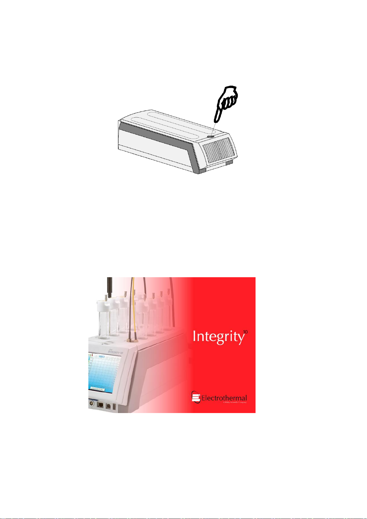
7.4.2. Press the button on top of the Power Supply Unit to commence operation. Observe the green
luminance of the power on switch.
The Integrity 10 can be used in conjunction with STEM Integrity control software, or it can be run in
standalone mode.
In standalone mode the Integrity 10 can be set up and run via manual control or via a profile set-up.
7.5. Turn Unit off.
7.5.1. Depress the Power Supply button once again to turn off the unit.
7.6. Splash Screen
7.6.1. When the Integrity 10 is first powered up it will go through a self check and warm up cycle. During
this time period a splash screen will be displayed.
Typical splash screen for the Integrity 10 Unit.
Page 17 of 80 M8024 Issue 3.4 For use with master product
software V3.5.1.8 and above.
7.6.2. After the Splash screen has been displayed the home screen will come into view.
7.7. Clock and Date Setting.
The first time the Integrity 10 system is used the time clock and date must be set. The clock and date
setting is performed using the following method. Accurate clock time is required when using data
storage facility as experiment data stored is time stamped.
7.7.1. With the Integrity 10 connected to mains power and water supply as detailed section 5, turn on as
detailed in 7.4
7.7.2. A splash screen will appear to indicate the unit is functioning and performing a self check activity.
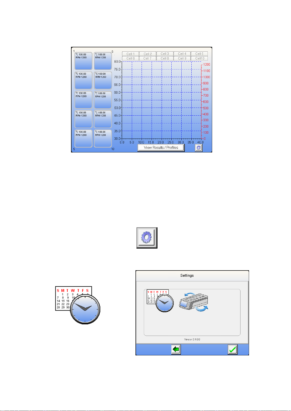
7.7.3. A home screen will appear. Touch the settings Icon to enter settings mode.
Note: Setting mode cannot be accessed if any cell positions are in use.
7.7.4. Touch the clock Icon to enter the clock and date settings mode.
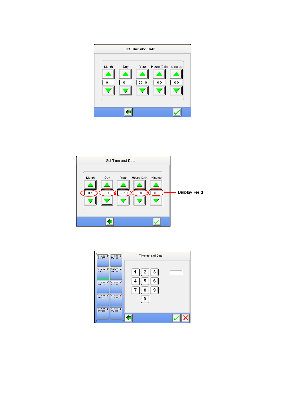
Page 18 of 80 M8024 Issue 3.4 For use with master product
software V3.5.1.8 and above.
7.7.5. From the clock setting screen use the up / down arrowed buttons to set the correct time and date.
7.7.6. Once the correct date and time has been entered press the Green tick button to accept the setting
entered. You are now taken back to the home screen from which you commence operation.
Alternative method. –May reduce button pressing.
7.7.7. Touch the display field you wish to set.
7.7.8. Select the setting required from the touch pad screen. Touch the green tick to except the setting or
touch the Red cross to clear the field and re-enter the field setting. The Green back arrow will take you
back to the previous screen.
Note: Daylight saving time settings will have to be adjusted using the time setting process as
described above.
Note: The date will automatically adjust for leap years.

Page 19 of 80 M8024 Issue 3.4 For use with master product
software V3.5.1.8 and above.
7.8. Communication Protocol Selection (For use with external control).
By default the communication protocol setting is factory set to receive and communicate data via the STEM
protocol. To change the protocol to accept GSIOC ensure your host system is communication platforms
protocol is GSIOC driven.
Follow the following procedure to change the setting.
7.8.1. With the Integrity 10 connected to mains power and water supply as detailed Section 5, turn on as
detailed in 7.4.
7.8.2. A splash screen will appear to indicate the unit is functioning and performing a self check activity.
7.8.3. A home screen will appear. Touch the settings Icon to enter settings mode.
Note: Setting mode can only be entered immediately after the Integrity has been switch on. Once
run settings have been made the setting icon will disappear.
To enter ‘settings mode’ at any time ensure all cells are turned off.
7.8.4. Touch the communication Icon in the settings screen to enter communication selection.
7.8.5. From selection screen touch the GSIOC facility selection.
Page 20 of 80 M8024 Issue 3.4 For use with master product
software V3.5.1.8 and above.
7.8.6. Touch the green back arrow return to the home screen.
Once the settings protocol has been changed the Integrity 10 must be switched off and then turned
back on before the new settings will become active.
Unless using this equipment with GSIOC protocol enabled systems leave the communication
protocol set for STEM.
7.9. View Firmware Release Set.
7.9.1. From the home screen touch the settings Icon to access the settings screen. The software version
set number is displayed across the bottom of the setting screen.
The Integrity 10 can be used in conjunction with STEM Integrity control software, or it can be run in
standalone mode.
In standalone mode the Integrity 10 can be set up and run via manual control or via a profile set-up.
7.10. Manual Control.
Note: Ice will form round the Integrity 10 cell assemblies when the unit is run for extended periods
at temperatures below 0°C
7.10.1. This is typical of the Home Screen which will generally be seen when the Integrity 10 is operational.
This view of the Home Screen is typical of the Integrity 10 without any cell position operational.
The graph area will represent real time data when the unit is running.
This manual suits for next models
1
Table of contents
Other Electrothermal Laboratory Equipment manuals


Popular Laboratory Equipment manuals by other brands


Rohde & Schwarz
Rohde & Schwarz R&S OSP Series user manual

Drucker Diagnostics
Drucker Diagnostics Horizon 6 FA Service manual

IKA
IKA C-MAG HS4 operating instructions

NuAire
NuAire LabGard NU-545-300E Operation and maintenance manual

Biosan
Biosan Multi Bio 3D operating manual

Bruker
Bruker Anton Paar user manual