Electrothermal EME Series User manual

Page 1 of 24 M8165 Issue 1.1
EME , SERIES ELECTROMANTLES.
INSTRUCTION BOOK

Page 2 of 24 M8165 Issue 1.1
Please take your time to read this Instruction book in order to understand the
safe and correct use of your new Electrothermal product.
It is recommended the Responsible Body for use of this equipment reads this
Instruction book and ensures the user(s) are suitably trained in its operation.
Contents.
Section 1.
Introduction
Page 3
Section 2.
Symbols and using this instructions book.
Page 4
Section 3.
Safety Information.
Page 5
Section 4.
Unpack and Contents.
Page 7
Section 5.
Installation.
Page 9
Section 6.
Environmental Protection.
Page 10
Section 7.
Product Operation.
Page 11
Section 8.
Technical Specification.
Page 14
Section 9.
Maintenance
Page 17
Section 10.
Replaceable Parts and Accessories
Page 20
Section 11.
Customer Support
Page 23
Section 12.
EC Declaration of Conformity.
Page 24
Appendix ‘A’
Decontamination Certificate
Page 22
©The copyright of this Instruction book is the property of Electrothermal. This Instruction book is supplied
by Electrothermal on the express understanding that it is to be used solely for the purpose for which it is
supplied. It may not be copied, used or disclosed to others in whole or part for any purpose except as
authorised in writing by Electrothermal. Electrothermal reserve the right to alter, change or modify this
document with out prior notification.
In the interest of continued development Electrothermal reserve the right to alter or modify
the design and /or assembly process of their products without prior notification.
This product is manufactured in Great Britian by Electrothermal. Part of the Bibby Group of
companies. Registered address.
Electrothermal.
Electrothermal House.
Unit12A, Purdeys Way.
Purdeys Industrial Estate.
Rochford,
Essex. SS4 1ND
Great Britain.
Tel +44(0)1702 303350
Fax+44(0)1702 468731

Page 3 of 24 M8165 Issue 1.1
1. INTRODUCTION.
1.1. The Electrothermal series of heating mantles has been specifically designed to
provide a comprehensive answer to heating fluids in round bottomed glassware in
the modern laboratory. It combines the traditional Electrothermal heating element
with many new features thus providing the user with several options to meet different
applications.
1.2. Heating control is provided by a built-in solid state energy regulator. Non stirring
mantles can be used with an external controller. (Please contact distributor /
manufacturer for details).
1.3. The enclosures of EME’s are housed in aluminium cases with a paint finish to give
good chemical resistance while the bowl surrounds are made from Polypropylene.
1.4. The products are provided with ventilation slots underneath and around the rim to
ensure a low enclosure surface temperature. The heating element is retained in
thermal Rockwool to create a heating cartridge that facilitates very easy replacement
in the event of any damage. All EME’s are supplied with support rods and clamps.
1.5. Electrothermal offers a comprehensive mantle range with the Standard cool-to-touch
vented case with element temperatures between ambient and 450 deg C.
1.6. EME Mantles are provided with the option of three or six recesses, built in solid-state
energy controllers and choice of heater or heater/stirrer combinations. Capacities for
flasks range from 100ml to 1000ml. All Extraction Mantles have individual energy
regulator with indicator light for each heater cartridge position, allowing liquids with
different boiling points to be heated alongside each other. The robust construction
permits continuous operation of the units as required by routine extraction tests.

Page 4 of 24 M8165 Issue 1.1
2. SYMBOLS AND USING THIS INSTRUCTION BOOK
2.1. Throughout this Instruction book the following symbols are shown
to identify conditions which pose a hazard to the user, or to identify actions that
should be observed. These symbols are also shown on the product, or its
packaging. When a symbol is shown next to a paragraph or statement it is
recommended the user takes particular note of that instruction in order to prevent
damage to the equipment or to prevent injury to one’s self or other people.
The Responsible Body and the Operator should read and be familiar with this
Instruction book in order preserve the protection afforded by the equipment.
To prevent injury or equipment damage it is the manufacturers
recommendation that all persons using this equipment are suitably trained
before use.
2.2. Symbols defined.
Caution, risk of danger. See note or
adjacent symbol.
This symbol adjacent to an indication lamp
means mains power Off/On when lamp non-
illuminated / illuminated
Protective conductor terminal to be
earthed.
(Do not loosen or disconnect).
This symbol adjacent to a switch denotes the Off
condition for mains power.
Caution / risk of electric shock
This symbol adjacent to a switch denotes the ON
condition for mains power.
Recyclable Packing Material.
This symbol adjacent to a switch denotes the Off
condition for the Heater or Stirrer.
Do not dispose of product in normal
domestic waste.
This symbol adjacent to a switch denotes the On
condition for a Heater or Stirrer.
Caution. Hot surface.
This symbol denotes stirrer speed control.
Refer to Instructions book
Bio Chemical Hazard. Caution required. Will
require decontamination.
Material irritant to skin. When handling wear face
mask to BS/EN 149 and protective gloves
Hot Zone on product
EME, EMEA.

Page 5 of 24 M8165 Issue 1.1
3. SAFETY INFORMATION.
This product has been designed for safe operation when used as detailed in accordance with
the Manufacturers instructions.
NOTE: Failure to use this equipment in accordance with the manufactures instruction book
may compromise your basic safety protection afforded by the equipment and may invalidate
the warranty / guarantee. The warranty / guarantee does not cover damaged caused by faulty
installation or misuse of the equipment
3.1. Prevention of Fire and Electric Shock.
To prevent a risk of fire or electric shock, DO NOT open your product
case without authorisation. Only qualified Service personnel should
attempt to repair this product.
Replace fuses only with the type as listed in section, ‘Technical
Specifications and Parts and Accessories’ (See fuse type and rating).
Ensure the Mains Power Supply conforms to rating found on the data
plate located on the back of this product.
Never Operate this equipment without connection to earth / ground.
Ensure the mains supply voltage is correctly earthed / grounded in
accordance with current area legislation.
3.2. General Safe Operating Practice.
Always follow good laboratory practice when using this
equipment. Give due recognition to your company’s safety and
legislative health & safety procedures and all associated legislation
applicable to your areas of operation. Check laboratory procedures for
substances being heated and ensure all hazards (e.g. explosion,
implosion or the release of toxic or flammable gases) that might arise
have been suitably addressed before proceeding. When heating
certain substances the liberation of hazardous gases may require the
use of a fume cupboard or other means of extraction.
Ensure equipment is used on a clean, dry, non-combustible, solid work
surface with at least 300mm suitable clearance all around from other
equipment.
Do not position the product so that it is difficult to disconnect from the
mains supply.
Do not touch the heating element or any glass vessel whilst in use.
Do not lean or stretch over equipment, glassware and fixings when in
use.
Do not immerse unit in water or fluids.
Do not spill substances onto the mantle. If spillage does occur,
disconnect unit from mains supply and follow instructions as detailed
in Maintenance. (Section 9).
Do not cover the mantle whilst in use. Do not block or obstruct
ventilation slots / airways.
Do not leave equipment switched on without a charged flask(s).
Do not thermally insulate the exposed upper section of the vessel(s),
as the insulation used may obstruct the convection
cooling airways around the rim of the cartridge enclosure and cause
the mantle to overheat.

Page 6 of 24 M8165 Issue 1.1
It is not recommended to leave any heating apparatus unattended
during operation.
Only use Original Equipment manufactures spares and accessories.
Ref Section 10.
Stirring versions of this equipment generate magnet fields. Keep all
metal objects and magnetic data devices (e.g. credit cards) away from
the stirrer unit.
The equipment is not spark, flame or explosion proof and has not been
designed for use in hazardous areas in terms of BSEN 60079-
14:1997. Keep flammable, low flash point substances away from the
apparatus.
Do not operate or handle any part of the product with wet hands.
Keep the Mains cord and moulded IEC plug and lead set away
from the heating surface.

Page 7 of 24 M8165 Issue 1.1
4. UNPACKING AND CONTENTS.
4.1. Product Identification:
A Catalogue number allocated to each type of mantle is descriptive. The method of coding is
detailed below.
First and second Characters
EME Series
Next Character
‘A’ unit with stir facility.
Next Character (if Multi bank)
3 or 6 = 3 way or 6 way.
Next four Characters
Flask size in ml. 0050, 0100, 0500, 1000,
Next Character after the /
‘C’ Controlled.
Next Character
‘E’ Earthed screen.
Last Characters
No Characters = 230V, X1 = 115V,
The following family tree outlines product variants.

Page 8 of 24 M8165 Issue 1.1
Please check the contents of your carton against the relevant product diagram.
Applicable to all EME product.
For future reference
please record your
products Serial and
Model Numbers.
Serial Number
Unit Model/Cat Number
Item
No
Description
Qty
1
EME product (6 way
shown).
1
2
Mains cord and moulded IEC
plug and lead set.
(May differ from illustration
depending on variant).
1
3
Support rods set. (2 of one
length and one of another).
1
4
Stir bars (bag of 3 or 6)
(EMEA Only).
1
5
Instructions book
1
6
Support rod clamps (packet).
1

Page 9 of 24 M8165 Issue 1.1
5. INSTALLATION.
5.1. Electrical safety and installation.
5.1.1. This equipment is designed to be used safely under the following conditions:-
Indoor use.
Altitude up to 2000 meters.
Temperatures between 5 C and 40 C.
Maximum relative humidity 80% for temperatures up to 31 C decreasing linearly
to 50% relative humidity at 40 C.
Mains supply voltage fluctuations up to 10% of the nominal voltage.
Transient overvoltages typically present on the mains supply. Overvoltage
category II
Applicable rated pollution degree 2.
5.1.2. This equipment must be earthed / grounded to a fixed earth / grounded
mains socket outlet. The mains supply is to earthed / grounded in accordance with
current legislation. See Technical Specification for recommended fuse ratings.
5.1.3. Ensure only the correct rated mains input fuses are fitted. (Where applicable
ensure the correct Mains cord and moulded IEC plug and lead set fuse if fitted).
See Technical Information Section 8 of this Instructions book.
5.1.4. Check the voltage on the product data label on this product unit and those of any
accompanying electrical accessory. Ensure the rating conforms to your local
supply.
5.1.5. This product should be connected to a mains supply source which incorporates a
RCD or GFCI device that has a tripping current of 30mA or less. The RCD or GFCI
residual Current Device cuts off power to the equipment immediately it detects a
current leakage fault. For example, cutting off the power when there is an
accidental liquid spillage in a mantle protected with an earth (ground) screen.
5.1.6. Do not install this product or accessories on a surface which may
become flooded.
5.1.7. The unit is supplied with a Mains cord and moulded IEC plug and lead set wired
as follows.
Green / Yellow
or
Green
=
Earth / Ground
Blue
or
White
=
Neutral
Brown
or
Black
=
Live / line hot.
5.2. Observation: the surface of the heating element of a mantle cartridge will upon receipt
look slightly discoloured. This discolouration is normal and occurs at the factory during
test when the mantle is first heated up.

Page 10 of 24 M8165 Issue 1.1
USA Notification.
Warning ! Any modification or changes made to this device, unless explicitly approved by Electrothermal
Engineering Limited, will invalidate the authorisation of this device. Operation of an unauthorised device is
prohibited under Section 302 of the Communications Act of 1934 as amended, and Subpart 1 of Part 2 of
Chapter47 of the code of Federal Regulations.
Note: This equipment has been tested and found to comply with the limits for a Class B digital device,
pursuant to part 15 of the FCC Rules. These limits are designed to provide reasonable protection against
harmful interference in a residential installation. This equipment generates, uses and can radiate radio
frequency energy and, if not installed and used in accordance with the instructions, may cause harmful
interference to radio communications. However, there is no guarantee that interference will not occur in a
particular installation. If this equipment does cause harmful interference to radio or television reception,
which can be determined by turning the equipment off and on, the user is encouraged to try to correct the
interference by one or more of the following measures:
Reorient or relocate the receiving antenna.
Increase the separation between the equipment and receiver.
Connect the equipment into an outlet on a circuit different from that to which the receiver is
connected.
Consult the dealer or an experienced radio/TV technician for help.
6. ENVIRONMENTAL PROTECTION.
6.1. Electrothermal has given due consideration to environmental issues within the design
and manufacturing process without compromising end product performance and value.
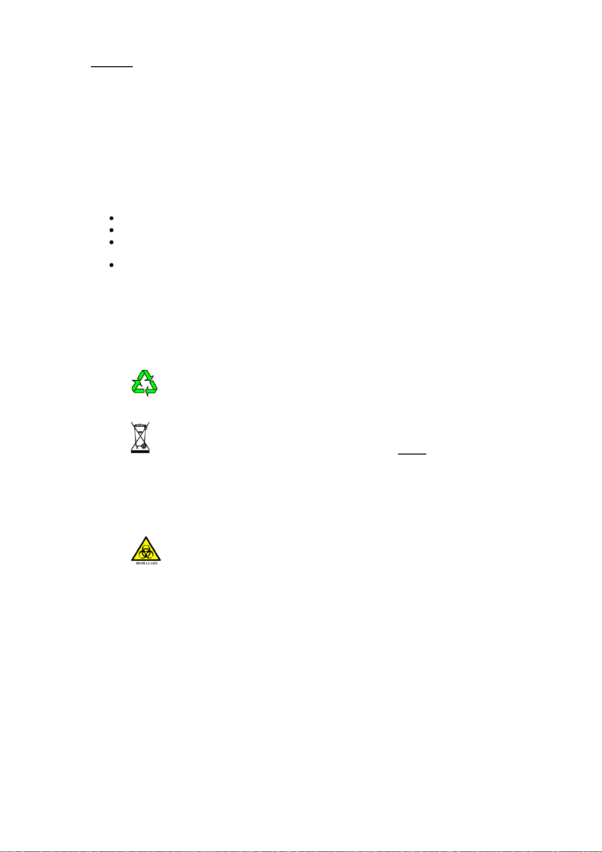
6.2. Packaging materials have been selected such that they may be sorted for
recycling.
6.3. At the end of your product and accessories life, it must not be discarded as
domestic waste. Ref: EU Directive 2002/96/EC on Waste Electrical and Electronic
Equipment Directive (WEEE). Please contact your distributor / supplier for further
information. For end users outside of the EU consult applicable regulations.
6.4. This product should only be dismantled for recycling by an authorised recycling
company.
This product and accessories must be accompanied by a completed
Decontamination Certificate prior to any disposal. Copies of the Certificate are
available from your distributor of Electrothermal products, or you may copy and
enlarge from ‘Appendix A’ of the instruction book.
Electrothermal is registered as Electrothermal Engineering Limited with the Environment Agency as a producer
of WEEE (Waste Electronic and Electrical Equipment) through b2b Compliance,an authorised waste collection
compliance scheme.

Page 11 of 24 M8165 Issue 1.1
7. PRODUCT OPERATION.
7.1. EME 3 and 6-way.
7.1.1. Overview of EME Mantle.
Item
Description.
1
Support Rods. (NB for 6 way units the support rod
arrangement is as per EMEA6 way).
2
Heating Element
3
Mains power on indicator
4
Heating element on
5
Energy regulator control knob
6
Warning Labels.
(Hot surface and refer to this Instruction book).
7
Mains input IEC socket (Contains protective fuses).
8
Rod support brackets
9
Data Plate
7.1.2. Fasten the rod supports provided into the mantle’s rod support location bracket
via the top cover holes.
7.1.3. With the mains supply electricity switch off, Connect the mains cord and moulded
IEC plug and lead set to the mains IEC socket.
7.1.4. Place a charged, clean, dry glass vessel of the size indicated on the mantle data
plate label in the positions intended for use. Wherever possible the glass vessel
should be supported within the mantle by means of the support rod and clamp.
7.1.5. Switch on the mains electrical supply. Adjust the controller regulator knob in each
position to the required setting.
NOTE: The mains power on indication neon will illuminate. The amber heating
on neon will illuminated in each position and pulsate (depending on setting)
when the heaters are in operation.
7.1.6. When the process is complete switch the regulator knobs to their off positions.
Disconnect the mains electricity supply.
7.1.7. Remove charged vessels. Handle hot charged vessel with care.

Page 12 of 24 M8165 Issue 1.1
7.2. EMEA 3 and 6-way.
7.2.1. Overview of EMEA Mantle.
7.2.2. Switch on the mains electrical supply. Adjust the controller regulator knob in each
position to the required setting.
NOTE: The mains power on indication neon will illuminate. The amber heating
on neon will illuminated in each position when the heaters are in operation.
Item
Description.
1
Support Rods and clamps (NB for 3 way units the
support rod arrangement is as per EME3 way).
2
Heating Element
3
Stir speed regulation
4
Mains power on indicator
5
Heating element on
6
Energy regulator control knob
7
Warning Labels.
(Hot surface and refer to Instructions book).
8
Fuse holders (Contains protective fuses).
9
Mains input IEC socket
10
Rod support brackets
11
Data Plate

Page 13 of 24 M8165 Issue 1.1
7.2.3. Fasten the rod supports provided into the mantle’s rod support location bracket
via the top cover holes and fit the cross bar using the clamps supplied.
7.2.4. With the mains supply electricity switch off, Connect the mains cord and moulded
IEC plug and leads set to the mains IEC socket.
7.2.5. Carefully place the stir bars provided into each vessel and turn the rotational
speed controls to the OFF (O –setting).
7.2.6. Place a charged, clean, dry glass vessel of the size indicated on the mantle data
plate label containing the stirrer bars in the positions intended for use. Wherever
possible the glass vessel should be supported within the mantle by means of the
support rod and clamp.
7.2.7. Switch on the mains electrical supply. Adjust the controller regulator knob in each
position to the required setting.
NOTE: The mains power on indication neon will illuminate. The amber heating
on neon will illuminate (and pulsate dependent on setting) in each position
when the heaters are in operation.
7.2.8. A single stirring module controls the stirring on the EMEA3. Two separate stirrer
modules and two controllers are used on the EMEA6. Each controller controlling the
stir function on the three mantle positions immediately to the right of the respective
control position.
Uni-directional stirring up to 800 RPM.
7.2.9. Switch the stir facility on. The neon will illuminate.
7.2.10. Adjust the rotational speed by means of the speed control knob. Should the
stirring action be lost by over rotation, then reduce the stir speed to minimum, wait
for the stir bar to come to rest and slowly re-increase the stir speed once more.
7.2.11. When the process is complete switch the regulator knobs to their off positions.
Disconnect the mains electricity supply.
7.2.12. Remove charged vessels. Handle hot charged vessel with care.

Page 14 of 24 M8165 Issue 1.1
8. TECHNICAL SPECIFICATION.
8.1. Specifications EME range (General).
Mains input supply voltage (115V-
AC).
115V –AC 10% at 50/60Hz.
Mains input supply voltage (230V –
AC).
230V –AC 10% at 50/60Hz.
Fuse type (EME-3, EMEA-3)
20mm x 5mm Glass Quick blow (F).
Fuse type (EME- 6,EMEA-6)
32mm x 6mm Glass Quick blow (F).
Operational climatic conditions.
Temperature range 5 C to 40 C. Humidity no to exceed
80%.
Heating Element Construction.
Thermal insulated element wire stitched into a cartridge
construction.
Maximum Element temperature.
450 C. Nominal Max
Case construction.
Polypropylene and coated aluminium.
Thermal Insulation
Ceramic Fibre or Mineral Wool.
Clamps for support rods.
½” (12.7mm) dia max.
Moulded IEC lead set EME6 and EMEA6 except
EMEA6 0500/CEx1, EMEA6 1000/CEx1, EME6 0500/CEx1, EME6 1000/CEx1
Mains cord and moulded IEC plug
and lead set cable (UK) 13A BS1362
AZ9165
3 core earthed / ground. 2 meters long
Moulded IEC plug and Lead set –supply cord H05 V V-
F- Replace only with equivalent cable.
Mains cord and moulded IEC plug
and lead set cable (Europe)
AZ6747
3 core earthed / ground. 2 meters long
Moulded IEC plug and Lead set –supply cord H05 V V-
F- Replace only with equivalent cable.
Mains cord and moulded IEC plug
and lead set cable (USA)
AZ6746
3 core earthed / ground. 2 meters long
Moulded IEC plug and Lead set –supply cord SJT VW
1- 105 Replace only with equivalent cable.
Mains cord and moulded IEC plug
and lead set cable (Switzerland)
AZ6175
3 core earthed / ground. 2 meters long
Moulded IEC plug and Lead set –supply cord
W W 05 VAS-F- Replace only with equivalent cable.
Mains cord and moulded IEC plug
and lead set cable (Australia)
M7079
3 core earthed / ground. 2 meters long
Moulded IEC plug and Lead set –supply cord
H05 V V-F Replace only with equivalent cable.
Lead set plug fuse (UK –only)
AZ9165
10A
IEC lead set for EMEA6 0500/CEx1, EMEA6 1000/CEx1, EME6 0500/CEx1,
EME6 1000/CEx1
20A Mains cord and IEC plug and
lead set. (USA) –
AZ4222
3 core earthed / ground. 2 meters long
Moulded IEC plug and Lead set –supply cord SJT V W
1 105 Replace only with equivalent cable.

Page 15 of 24 M8165 Issue 1.1
8.1.1. Power consumption and fuse rating.
Type
Size
Total Heating Power (Watts).
Fuse rating (Amps)
230V
115V
230V
115V
EME3
100ml
3x60
3x70
F3
F3
EMEA3
100ml
3x60+40(Stir)
3x60+40 (Stir)
F3
F3
EME3
250ml
3x150
3x150
F3
F5
EMEA3
250ml
3x150+40(Stir)
3x150+40(Stir)
F3
F6.3
EME3
500ml
3x200
3x200
F3
F6.3
EMEA3
500ml
3x200+40(Stir)
3x200+40(Stir)
F6.3
F6.3
EME3
1000ml
3x300
3x300
F5
F10
EMEA3
1000ml
3x300+40(Stir)
3x300+40(Stir)
F6.5
F10
EME6
100ml
6x70
6x60
F3
F5
EMEA6
100ml
6x70+80(Stir)
6x60+80(Stir)
F3
F6.3
EME6
250ml
6x150
6x150
F5
F10
EMEA6
250ml
6x150+80(Stir)
6x150+80(Stir)
F6.3
F10
EME6
500ml
6x200
6x200
F6.5
F15
EMEA6
500ml
6x200+80(Stir)
6x200+80(Stir)
F6.3
F15
EME6
1000ml
6x300
6x300
F10
F10
EMEA6
1000ml
6x300+80(Stir)
-
F10
-
8.1.2. The Ingress protection rating for the EM product range is IPX0.
8.1.3. Dimensions and weight (unpacked).
EMEx3, EMEAx3 100ml
WEIGHT 6.2Kg
EMEx3, EMEAx3 250ml
WEIGHT 6.2Kg
EMEx3, EMEAx3 500ml
WEIGHT 7.4Kg

Page 16 of 24 M8165 Issue 1.1
EMEx3, EMEAx3 1000ml
WEIGHT 7.4Kg
EMEx6, EMEAx6 0100ml
WEIGHT 10.1Kg
EMEx6, EMEAx6 250ml
WEIGHT 10.1Kg
EMEx6, EMEAx6 500ml
WEIGHT 12.5Kg
EMEx6, EMEAx6 1000ml
WEIGHT 12.5Kg

Page 17 of 24 M8165 Issue 1.1
9. MAINTENANCE.
9.1. General Information.
Unplug the unit from the mains voltage supply and allow it to cool before
undertaking any maintenance tasks.
Maintenance should only be carried out under the direction of the Responsible
Body, by a competent electrician. Failure to do so may result in damage to the product
and in extreme cases be a danger to the end user.
With proper care in operation this equipment has been designed to give many years of
reliable service. Contamination or general misuse will reduce the effective life of this
product and may cause a hazard.
Maintenance for the unit should include:
Periodic electrical safety testing (an annual test is recommended as the minimum
requirement).
Regular inspection for damage with particular attention to the mains lead and
plug set.
Routine cleaning of the equipment should be undertaken using a clean cloth.
DO NOT USE SOLVENTS FOR CLEANING ANY PART OF THIS
EQUIPMENT.
9.2. Fuse Replacement.
The mains fuse holder is located at rear your product. Refer to Technical specification,
‘Fuse Rating’ for correct fuse type and rating. Turn your product off and disconnect it from
the mains supply.
EME6-way Mantle: Unscrew both fuse holder caps from the fuse housings and
remove the fuses. Fit replacement fuses of the correct rate and value.
EME3 –way Mantle: Open the draw of the IEC mains electrical input socket. Remove
fuses and fit replacement fuses of the correct rate and value.
OR
EME6-way Mantle: EME3 –way Mantle

Page 18 of 24 M8165 Issue 1.1
9.2.1. Heater Cartridge replacement.
Attention. The heater contains insulation material made from
Refractory Ceramic Fibres (RCF), classified as a category 2 carcinogenic
under EU Directive 67/548/EC. Follow the guidelines for working with RCF
as laid down under in the ECFIA Code of Practise. Wear suitable protective
clothing and gloves.
EME and EMEA mantles contain Rockwool mineral insulation.
When handling a suitable face mask which bears the CE mark should be
used. A face mask to BS/EN 149 is adequate. When handling, wear gloves.
Should skin irritation be experienced it can be lessened by rinsing hands
under cold running water before washing. For further information refer to
guidance note EH46 published by HMSO and technical data sheets
available from Rockwool Limited. Pencoed. Bridgend. CF35 6NY.
In the event of a heater element becoming damaged or open circuit the follow
procedure should be adopted for its replacement.

Page 19 of 24 M8165 Issue 1.1
EME and EMEA
9.2.1.1. Unplug or disconnect the mantle from the mains electricity supply.
9.2.1.2. Remove the cross-head fixing screws from the lid and lift the lid off.
9.2.1.3. EME / EMEA, Disconnect the lid to base earth wire.
9.2.1.4. Remove the three M3 cartridge retention nuts and disconnect the cold leads
from the temperature controller PCB.
9.2.1.5. Reverse this process to fit the new cartridge assembly. On EMEA product
ensure the cold leads do not obstruct the stir belt.
9.2.1.6. Replace the earth lead and base and refasten using the previously removed
cross-head fixing screws.
9.2.1.7. The responsible body shall check the electrical safety of the product before
further use.
9.3. Spillage and Decontamination.
In the event of spillage switch off and unplug this product from the mains electrical
supply. Wipe off all excess liquid from the mantle element earth mesh and surrounding
area using an absorbent soft cloth. Allow sufficient time for any ingressed liquid to
evaporate before commencing with use.
If in doubt please consult Customer Support. Refer to section 11.
If the equipment has been exposed to contamination, the Responsible
Body is responsible for carrying out appropriate decontamination. If hazardous
material has been spilt on or inside the equipment, decontamination should only
be undertaken under the control of the Responsible Body with due recognition of
possible hazards. Before using any cleaning or decontamination method, the
Responsible Body should check with the manufacturer the proposed method will
not damage the equipment.
Prior to further use, the Responsible Body shall check the electrical safety of the
unit. Only if all safety requirements are met can the unit be used again. The above
procedure is intended as a guide. Should spillage occur with a toxic or hazardous
fluid then special precautions may be necessary.
Decontamination Certificate.
Note: In the event of this equipment or any part of the unit becoming damaged, or
requiring service, the item(s) should be returned to the manufacturer for repair
accompanied by a decontamination certificate. Copies of the Certificate are available
from Distributor/Manufacturer. Appendix A of this instructions book may be
copied and enlarged.
At the end of life, this product must be accompanied by a Decontamination
Certificate. See section 6.3 and 6.4

Page 20 of 24 M8165 Issue 1.1
10.PARTS AND ACCESSORIES
10.1. Replacement Heater Cartridges. All Electrothermal mantles are specified by
the letters RE and Flask size. Add x1 suffix when ordering for 115V
Mantle model type
Replacement heater Cartridge.
EME0100/CEB (3 & 6 way).
Order
REME0100
EME0250/CEB.(3 & 6 way).
Order
REME0250
EME0500/CEB.(3 & 6 way).
Order
REME0500
EME1000/CEB. (3 & 6 way).
Order
REME1000
EMEA0100/CE (3 & 6 way)
Order
REMEA0100
EMEA0250/CE (3 & 6 way)
Order
REMEA0250
EMEA0500/CE (3 & 6 way)
Order
REMEA0500
EMEA1000/CE (3 & 6 way)
Order
REMEA1000
10.2. Replaceable parts.
Order Number
Description.
Quantity
AZ9165
Mains cord and moulded IEC plug and lead set (UK) 230V-AC
1
AZS4222
Mains cord and moulded IEC plug and lead set (USA) 115V-AC –
(EMEA6 0500/CEBx1, EME6 1000/CEBx1, EMEA6 0500/CEx1,EMEA6 1000/CEx1).
1
AZ6746
Mains cord and moulded IEC plug and lead set (USA) 115V-AC
1
AZ6747
Mains cord and moulded IEC plug and lead set (Europe) 230V-AC
1
AZ9021
Solid state Simmerstat assembly (90 -250V-AC).
1
AZ9033
Fuse: F15A
10
AZ9034
Fuse: F10A
10
AZ9035
Fuse: F8A
10
AZ9036
Fuse: F6.3A
10
AZ9038
Fuse: F0.5A
10
AZ9039
Fuse: F1.25A
10
AZ9040
Fuse:F2.5A
10
AZ9041
Fuse: F3.15A
10
AZ9065
Fuse: F12.5A
10
AZ9130
Fuse; F3A
10
M5607
Neon: Clear (230V)
1
M5608
Neon: Amber (230V)
1
M5619
Neon: Clear (115V)
1
M5620
Neon: Amber (115V)
1
M5621
Switch, Element Selection (EMX, EMV).
1
M5792
Speed Control Potentiometer (EMA only).
1
M5821
L.E.D. Green (90 –230V) (EMA only).
1
129320/3
Support rod (710mm / 28 “ long).
1
129320/4
Support rod (1160mm / 45” long).
1
129320/5
Support rod (1440mm / 55” long).
1
129320/6
Support rod (590mm / 23” long).
1
This manual suits for next models
8
Table of contents
Other Electrothermal Laboratory Equipment manuals
Popular Laboratory Equipment manuals by other brands

THORLABS
THORLABS PD2 user guide

H.E. Anderson
H.E. Anderson Ratio:Feeder J Plus Series Installation Guidelines and Operation

Idexx
Idexx Filta-Max xpress Operator's guide

DEMA
DEMA 163CH installation instructions

Thermo Scientific
Thermo Scientific 1300 Series operating manual

Pelton & Crane
Pelton & Crane Validator Plus user manual