Pall Minimate EVO TFF User manual

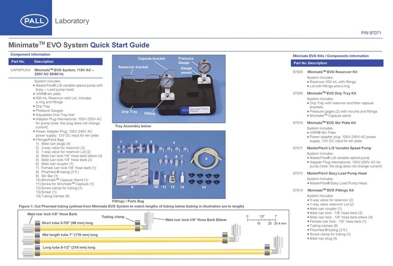
Tray Assembly
Component information
Part No: OAPMPUNV
Description: Minimate EVO TFF System,
115V AC – 230V AC 50/60 Hz
System includes:
•MasterFlex L/S variable speed pump
with Easy – Load pump head
•VWR stir plate
•500 mL Reservoir with Lid, includes
o-ring and ttings
•Drip Tray
•Pressure Gauges
•Adjustable Drip Tray feet
•Adapter Plug international, 100V-250V
AC for pump (note: the plug does not
change current)
•Power Adapter Plug, 100V-240V AC
power supply, 12V DC input for
stir plate
Fittings/Parts Bag:
1) Male luer plugs (4)
2) 3-way valve for reservoir (2)
3) 1-way valve for reservoir Lid (2)
4) Male luer lock-1/8” hose barb elbow (4)
5) Male luer lock-1/8” hose barb (3)
6) Male luer coupler (1)
7) Female luer lock-1/8” hose barb (1)
8) PharMed tubing (2 ft.)
9) Stir Bar (1)
10) Minimate Capsule Stand (1)
11) Screw for Minimate Capsule (1)
12) Screw clamp for tubing (1)
13) Sinker (1)
14) Tubing clamps (8)
QUICK START GUIDE
MinimateTM EVO TFF System
Fittings/Parts Bag
Minimate EVO TFF Kits / Components Information
Part No. Description
97008
Minimate EVO TFF Reservoir Kit.
System includes:
• Reservoir 500 mL with ttings
• Lid with ttings and o-ring
97009
Minimate EVO TFF Drip Tray Kit
System includes:
• Drip Tray with reservoir and lter capsule brackets
• Pressure gages (2) with mounts and ttings
• Minimate Capsule stand
97010
Minimate EVO TFF Stir Plate Kit
System includes:
• VWR Stir Plate
• Power adapter plug, 100V-240V AC power supply, 12V DC input
for stir plate
97011
MasterFlex L/S Variable Speed Pump
System includes:
• MasterFlex L/S variable speed pump
• Adapter Plug international, 100V-250V AC for pump (note: the
plug does not change current)
Part No. Description
97012
MasterFlex Easy Load Pump Head
System includes:
• MasterFlex Easy Load Pump Head
97014
Minimate EVO TFF Fittings Kit includes:
• 3-way valve for reservoir (2)
• 1-way valve reservoir Lid (2)
• Male luer coupler (1)
• Male luer lock - 1/8” hose barb (3)
• Male luer lock - 1/8” hose barb elbow (4)
• Female luer lock - 1/8” hose barb (1)
• Tubing clamps (8)
• PharMed tubing (2 ft.)
• Screw clamp for tubing (1)
• Male luer plug (4)
1 2 3 4
5 6 7
9
8
10 11 12 13 14
Drip tray
Fitting
Capsule
bracket
Pressure
gauge
Gauge
mount
Reservoir
bracket

Assemble System
Installation
1. Verify all components have been provided. (See
Tray Assembly and Fittings/Part Bag gures on
reverse side)
2. Cut PharMed tubing (yellow) to lengths as specied
(See page 3)
3. Slide tube clamps onto tubing and insert ttings into
tubing as shown on back page. Slide clamps over
tting ends and pinch together (use pliers if
necessary to assist)
4. Lay drip tray on work counter. (Note: if there is any
rocking of tray, the bottom feet can be adjusted by
rotating as necessary as shown in gure 1)
5. Slide stir plate into left compartment of drip tray
underneath reservoir bracket. Attach capsule stand on
raised boss in center of drip tray with screw in threaded
hole. Turn screw until snug t, but allows the stand to
move. (See gure 2)
6. Connect 3-way valves to ttings on reservoir outlet
and inlet. Attach male luer plugs onto female luer
connectors on 3-way valves. (See gure 3)
7. Place reservoir onto stir plate with outlet toward rear
of plate. (See gure 4)
8. Connect “long tube” to 3-way valve at reservoir outlet
and to tting on rear gauge mount. (See gure 4)
9. Attach pump head onto pump with supplied screws.
(See gure 5)
Figure 2
Figure 3
Figure 4
Figure 1
Stir plate
Capsule
stand
3-Way valve
on inlet
3-Way valve
on outlet
Male luer
pugs
Long tube
Reservoir
3-way
valve
Pump
Pump
head
Mounting
screws
Figure 5

10. Place tray in front of pump and insert tubing into
open pump head, close pump head onto tubing.
(See gure 6)
11. Perform the tubing break-in procedure
NOTE: The break-in procedure needs to be performed
on new tubing to properly stretch and condition the
tubing. If this procedure is not completed, the pump
head rollers can split the tubing, resulting in product
loss. It is critical to properly load tubing into the pump
head to ensure proper operation and to avoid damage
to the tubing
Follow the procedure below for non-silicone tubing to
break-in, stretch, and reseat new PharMed L/S 16
tubing prior to running the instrument with sample:
a. Set up the Minimate EVO TFF System as per the
instructions, but do not install the capsule
b. Install a piece of tubing from the feed pressure
gauge back to reservoir (see gure 6)
c. Run the system with 200 ml of water, using one of
the RPM and break-in times listed in Table 1
d. After the time has elapsed, drain the system by
running the water to a waste container instead of
the reservoir, open the pump head, examine the
tubing to make sure it is not damaged, and re-insert
e. Close the pump head and continue with the
ushing procedure
12. Attach male luer coupler to tting on front of gauge
mount. Attach Minimate Capsule feed port to coupler,
rotate capsule to left into capsule stand and onto
capsule bracket for support. (See gure 7)
13. Connect “mid-length” tube to tting on rear of
forward gauge mount and to retentate port on
capsule lter. (See gure 7)
Tubing length diagram
Cut PharMed tubing (yellow) from Minimate EVO TFF
System to match lengths of tubing below (tubing in
illustration are to length)
2010 25.4 mm
1”
01 /2”
Mid length tube 7” (178 mm) long
Long tube 8-1/2” (216 mm) long
Male luer lock-1/8” Hose Barb
Short tube 3-7/8” (99 mm) long
Tubing clamp
Male luer lock-1/8” Hose Barb Elbow
Figure 6. Minimate assembled and ready to run the tubing
break-in procedure
Table 1. Tubing break-in conditions. Masterex L/S 16 tubing is
non-silicone tubing.
RPM Silicone Break-In Time (minutes) Non-Silicone Break-In Time (minutes)
600 10 20
300 20 40
100 60 120

Corporate Headquarters
Port Washington, NY, USA
+1-800-717-7255 toll free (USA)
+1-516-484-5400 phone
European Headquarters
Fribourg, Switzerland
+41 (0)26 350 53 00 phone
Asia-Pacic Headquarters
Singapore
+65 6389 6500 phone
Visit us on the Web at www.pall.com/laboratory
Contact us at www.pall.com/contact
Pall Corporation has offices and plants throughout the world. To locate the Pall office
or distributor nearest you, visit www.pall.com/contact.
The information provided in this literature was reviewed for accuracy at the time of
publication. Product data may be subject to change without notice. For current
information consult your local Pall distributor or contact Pall directly.
GN21.0712
Figure 8
One way valve
Reservoir lid
Dialtration
vessel
Female luer – barb
(to ltrate port)
Filtrate
collection
vessel
14. Connect “short tube” to tting on front of gauge
mount and to 3-way valve on reservoir inlet. Attach
adjustable screw clamp to tube. Remove clamp
when not in use, tubing can deform over time
without uid passing through tubing. (See gure 7)
15. Cut a length of tubing from Minimate Capsule
packaging long enough to reach ltrate collection
vessel from ltrate port on lter capsule. Attach
tubing clamp and female luer-1/8” hose barb to tube
Connect tting to ltrate port and place open tube
end into ltrate receiver vessel. (See gure 8)
16. If performing dialtration, place lid onto reservoir.
Connect 1-way valves onto ttings on top of
reservoir. From the Minimate Capsule lter
packaging, cut a length of tubing to reach from
1-way valve on reservoir lid top to dialtration vessel
Attach male luer-1/8” hose barb elbow and tubing
clamp. Attach elbow to 1-way valve on lid and other
tube end into dialtration vessel, sinker at end of
tube optional. (See gure 8)
Operation
■Conrm all ttings are secure prior to running liquid
through system
■Refer to VWR stir plate operating manual for
operation of stir plate. Use of reverse mode is not
recommended on stir plate with Minimate EVO
TFF System. If stir bar stops rotating when increasing
stir plate speed, reduce speed until stir bar is
again spinning
■Refer to MasterFlex Pump and Pump Head
manuals for use
■Refer to Minimate Instructions for use for operation
of the TFF capsule
Figure 7
Retentate port
Screw
clamp
Short
tube
Mid
length
tube
Male luer coupler
(to feed port)
© Copyright 2022, Pall Corporation. Pall, , Centramate, Minimate, and Omega are
trademarks of Pall Corporation. ® Indicates a trademark registered in the USA. PharMed
is a register trademark of Saint-Gobain, VWR and Masterflex are registered trademarks of
Avantor, Inc. or affiliates.
This manual suits for next models
1
Other Pall Laboratory Equipment manuals

Pall
Pall Envirochek User manual

Pall
Pall USD3295 User manual

Pall
Pall Allegro MMG403 User manual

Pall
Pall 4821A User manual

Pall
Pall Allegro User manual

Pall
Pall Jet Mixer User manual

Pall
Pall T Series Guide

Pall
Pall Allegro 200 L User manual

Pall
Pall Minimate TFF User manual

Pall
Pall Allegro 1000 L User manual