Elektra Beckum Welding Transformers and Rectifiers SB 160 C User manual

115 117 9491 / 2402 - 3.2 / de, en, fr, nl
Achtung! Lesen Sie diese Anleitung vor der Installation und Inbetriebnahme aufmerksam durch.
Attention! Carefully read through these instructions prior to installation and commissioning.
Attention ! Prière de lire attentivement la présente notice avant l'installation et la mise en service.
Oppassen! Lees deze instructies voor de installatie en ingebruikname aandachtig door.
Betriebsanleitung
Schweißgeräte mit stufenloser Regelung
Operating Instructions
Welding Transformers and Rectifiers
with Stepless Current Control
Instructions d'utilisation
Appareil de soudure avec réglage en continu
Handleiding
Lasapparaten met traploze instelling
SB 160 C / SB 200 CT

D DEUTSCH ENG ENGLISH
KONFORMITÄTSERKLÄRUNG DECLARATION OF CONFORMITY
Wir erklären in alleiniger Verantwortlichkeit, daß dieses Produkt mit
den folgenden Normen übereinstimmt* gemäß den Bestimmungen
der Richtlinien**.
We herewith declare in our sole responsibility that this product
complies with the following standards*
in accordance with the regulations of the undermentioned Directives**
F FRANÇAIS NL NEDERLANDS
DECLARATION DE CONFORMITE CONFORMITEITSVERKLARING
Nous déclarons, sous notre seule responsabilité, que ce produit est en
conformité avec les normes ou documents normatifs suivants* en
vertu des dispositions des directives **
Wij verklaren als enige verantwoordelijke, dat dit product in
overeenstemming is met de volgende normen*
conform de bepalingen van de richtlijnen**
IT ITALIANO ES ESPAÑOL
DICHIARAZIONE DI CONFORMITÀ DECLARACION DE CONFORMIDAD
Noi dichiariamo sotto la nostra esclusiva responsabilità che il presente
prodotto è conforme alle seguenti norme*. in conformità con le
disposizioni delle normative **
Declaramos bajo nuestra exclusiva responsabilidad, que el presente
producto cumple con las siguientes normas*.de acuerdo a lo
dispuesto en las directrices**
PT PORTUGUÊS SV SVENSKA
DECLARAÇÃO DE CONFORMIDADE FÖRSÄKRAN OM ÖVERENSSTÄMMELSE
Declaramos sob nossa responsabilidade que este produto está de
acordo com as seguintes normas*.de acordo com as directrizes dos
regulamentos **
Vi försäkrar på eget ansvar att denna produkt överensstämmer med
följande standarder*. Enligt bestämmelserna i direktiven**
FIN SUOMI NO NORGE
VAATIMUKSENMUKAISUUSVAKUUTUS SAMSVARSERKLÆRING
Vakuutamme, että tämä tuote vastaa seuraavia normeja*.on
direktiivien määräysten mukainen**
Vi erklærer under eget ansvar at dette produkt samsvarer med
følgende normer*. henhold til bestemmelsene i direktiv**
DA DANSK POL POLSKI
OVERENSSTEMMELSESATTEST OŚWIADCZENIE O ZGODNOŚCI
Hermed erklærer vi på eget ansvar, at dette produkt stemmer overens
ed følgende standarder*. iht. bestemmelserne i direktiverne**
Oświadczamy z pełnąodpowiedzialnością, że niniejszy produkt
odpowiada wymogom następujących norm*.według ustaleń
wytycznych **
EL ΕΛΛHNIKA HU MAGYAR
∆ΗΛΩΣΗ ΑΝΤΙΣΤΟΙΧΕΙΑΣ MEGEGYEZŐSÉGI NYILATKOZAT
∆ηλώνουµεµειδία ευθύνη ότι το προϊόν αυτό αντιστοιχεί στις
ακόλουθες προδιαγραφές*
σύµφωνα µετις διατάξεις των οδηγιών**
Kizárólagos felelősségünk tudatában ezennel igazoljuk, hogy ez a
termék kielégíti az alábbi szabványokban lefektetett
követelményeket*.megfelel az alábbi irányelvek előírásainak**
SB 160 C - SB 200 C
T
* EN 50060; EN 55014 (1993); DIN EN 61000-4-1 (1993), EN 60974-1
** 89/336/EWG, 73/23/EWG
Dipl. Ing. Jürgen Kusserow
Vorstand
ELEKTRA BECKUM AG – Daimlerstraße 1– 49716 Meppen
Tel.: +49 59 33 80 20
1000965/ 00

1 Specifications
2 Taking a Single-Phase Machine Into Operation
2.1 Taking a Combination 1-Ph/2-Ph Machine into Operation
3 General Information for Welding Transformer/Rectifier Operators
3.1 Overview of Stick Electrodes and their correct Use
3.1.1 Care of Stick Electrodes
3.1.2 Function of the Stick Electrode Coating
3.1.3 Classification of Stick Electrodes according to DIN 1913
3.1.4 Selecting Suitable Electrodes for a Welding Task
3.1.5 Arc Starting and Arc Burning
3.1.6 Welding Positions According to DIN 1921
4 Welding Hints
4.1 Weld Types
4.2 Weld Flaws and possible Causes - Shown on Fillet Welds
5 Accessories and Accessory Maintenance
6 Wiring Diagrams
Contents
ENG
13
User Responsibility
You have bought a high-quality electric arc welding machine, designed and built by specialists with many years of
experience. A machine built to last, giving a long service life.
All models have the correct size power supply cable fitted, the transformer‘s core is made from top-quality insulated
sheet steel, to keep eddy currents and cyclic magnetization losses to an absolute minimum.
Please read the instructions given in the manual in order to fully utilize the potential of your machine.
Know and adhere to all local safety codes and regulations governing the operation of electric arc welding machines.
The operation of the welding divice in the data processing system environment is not allowed!
This product shall only be used as specified. Any other use requires the written consent of Elektra Beckum AG,
P.O.Box 1352, D-49703 Meppen, Germany
Please contact your dealer for any warranty claims.
Warranty work will essentially be carried out by service centres authorised by us. Repairs beyond the warranty
period may be carried out only by our authorised service centres.
Please preserve all repair invoices! We reserve the right to make technical changes!
We recommend attending a welding course at a recognised technical institute.
2 Taking a Single-Phase Machine into Operation
This machine is to be connected to the power mains via a Earth Fault Circuit Interrupter of 30 mA capacity. Worn
or damaged power cables should be replaced immediately by a qualified electrician.
Do not operate this machine with a damaged power cable, danger of personal injury by electric shock.
Children are not permitted to operate this machine.
Connect to an earthed single-phase 230/240 V outlet, protected by a 16 A time-lag fuse. Operating other electric
machines or appliances on the same circuit while welding is only possible to a very limited extent and not
recommended.
Earth and welding cable are firmly attached to the machine.
Polarity does not matter with AC welding current.
1 Specifications
Model SB 160 C SB 200 CT SB 200 CT
Main voltage 230/400 V 240 V 230/400 V
Mains frequency 50/60 Hz 50 Hz 50/60 Hz
Welding steps stepless stepless stepless
Stepless at 230 V 32 - 38 V 47 - 55 V 31 - 39 V
Stepless at 400 V 38 - 46 V 41 - 50 V
Max. OCV at 230 V 16 A time-lag 32 A time-lag 16 A time-lag
Max. OCV at 400 V 16 A time-lag 20 A time-lag
Insulation class H H H
Protection class IP 21 IP 21 IP 21
Setting range, stepless 230 V 30 - 110 A 70 - 180 A 20 - 110 A
Setting range, stepless 400 V 65 - 155 A 60 - 180 A
Cooling self fan fan
Weldable electrodes at 230 V Ø 1.6 - 2.5 mm Ø 2,0 - 4,0 mm Ø 1.6 - 2.5 mm
Weldable electrodes at 400 V Ø 2.0 - 3.25 mm Ø 2.0 - 4.0 mm

Example:
Stick electrode DIN 913 - E 43 3 2 AR 7
Type of electrode Number of DIN standard
Code for manual electric arc welding
Code number for tensile strength,
yield point and elongation
Code number for impact
engergy of 28 Joule minimum
Code number for increased impact
energy of 47 Joule minimum
Code for coating
Code number for electrode class
3.1 Care of Stick Electrodes and their correct Use
3.1.1Coding of Stick Electrodes according to DIN 1913
In order to achieve a good weld the electrode has to be dry, thus storing in a dry place is essential- Should
electrodes have become moist, dry in an oven at between 200°C to 300°C for 30 minutes.
Basic coated low-hydrogen type electrodes always require pre-drying at 200°C to 300°C for 3 hours as atomic
hydrogen causes weld flaws.
The designation of welding electrodes is standardized by DIN 1913. The designation is stipulated by the
electrode manufacturers in accordance with the standard and checked by an inspection body. It is printed on
the electrode packet.
14
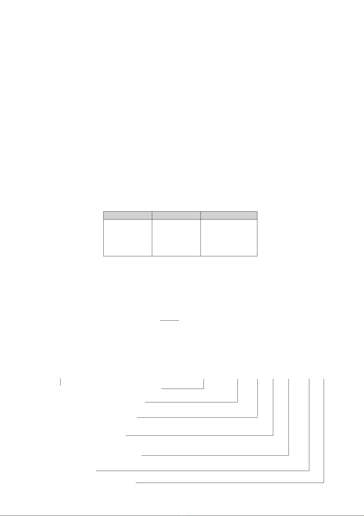
Select the correct welding current as shown below:
Current (A) Electrode Ø Material Thickness
25 - 50 1.0 - 2.0 mm 1.0 - 2.0 mm
50 - 100 2.0 - 2.5 mm 2.0 - 4.0 mm
100 - 140 2.5 - 3.25 mm 4.0 - 8.0 mm
140 - 220 3.25 - 5.0 mm 8.0 - 12.0 mm
220 - 300 5.0 - 6.0 mm 12.0 - 20.0 mm
In principle do not use too thick an electrode. As a general rule calculate 40 amps welding current per 1 mm of
electrode diameter. Depending on electrode type, material thickness and weld position this calculated value may
have to be adjusted to plus or minus. All machines work well with thin plate from 1.0 mm thickness.
3 General Information for Welding Transformer/Rectifier Operators
Dust, dirt and metal chips will harm any welding machine. It is of particular importance that the air ventilation for
cooling is not obstructed.
A weld should join two work pieces as if they were made from a single piece. Prior to the welding the joints must
be cleaned and dirt, rust, grease and paint removed. Also slag from previous welds must be completely removed.
Attach earth clamp firmly to work piece, assuring good metal to metal contact. Check that all cables and
connectors are in proper operating condition to ensure proper current conduction.
Place electrode with the uncoated end into one of the electrode holder's notches. Each welding machine is
supplied complete with an accessory kit, comprising the welding cables, a welding visor and a slag hammer.
When removing slag it is recommended to protect the eyes by suitable means (goggles) from injury by sharp and
hot slag. The welding visor's dark glass plate protects the eye against ultra-violet and infrared rays. The clear
glass plate protects the dark plate against spatters and damage. The dark protective glass is available in different
shades for different types of electrodes and to suit different eye sensivity. Normally for electrodes from 1.5 mm
to 4 mm Ø protective glasses of shade DIN 9 are used, for electrode over 4 mm Ø shade DIN 10.
Attach earth clamp to the workpiece, close to the weld seam and on bare metal for good conduction.
Place stick electrode into the electrode holder.
With the handwheel select the desired welding current.
If there is not power outlet near the work area an extension cable is required. The cable's lead cross section must be
at least 2.5 mm2. Uncoil extension cable fully to prevent heatbuild-up by inductance. Inductance also conside-rably
reduces the welding current. Extension of the welding cables is also possible, but the cross section of the extension
cables must be larger than that of the cables supplied with the machine.
Every machine is protected against overloads by a thermo switch, which switches the power to the transformer off if it
becomes too hot. After a short cooling-down period the machine will switch back on automatically. Model SB 200 CT
is equipped with a fan for forced cooling, given better performance with a higher duty-cycle.

3.1.2Function of the Stick Electrode Coating
Stabilization of the
arc and lonization
of the arc space
Protection of the weld
metal from atmospheric
oxygen and nitrogen
This protection is achieved by the generation of shielding gases and slag during the
melting of the electrode.
Compensation of alloy burn-off.
bare
electrode
unstable
arc
coated
electrode
stable
arc
coated
electrode
slag shielding gas
bare
electrode
Coating thickness
Penetration depth
Weld seam appearance
Gap bridging ability
Material transfer
D
d
DD
dd
light
D = 1.2 · d
=
heavy
D > 1.55 · d
medium
D > 1.2 · d
but <1.55 · d
Stick Electrodes According to DIN 1913
A acid coated
R rutile light and medium coating
RR rutile heavy coating
AR rutile acid coating
C cellulose coating
R(C) rutile cellulose medium coating
RR(C) rutile cellulose heavy coating
B basic coating
B(R) basic coating with non-basic proportions
RR(B) rutile basic heavy coating
Types of Coating
15
This manual suits for next models
3
Table of contents
Other Elektra Beckum Welding Accessories manuals