ELEKTROBOCK Pocket home PH-PK20 User manual

PH-PK20
WIRELESS RECEIVER FOR BOILER
Wireless receiver for boiler control
PocketHome® system component
Two-way radio communication on 433.92 MHz
Indication of state by coloured LED
Superior component is the central unit PH-CJ37
Power supply 230 V/ 50 Hz
Operating instructions PH-PK20
version 10.01
WALL-MOUNTED
TECHNICAL CHARACTERISTICS
Power supply 230 V/ 50 Hz
Communication type two-way
Frequency 433,92 MHz
Range 300 m (in open space), 35 m (in built-up area)
Protection IP20
Output relay, max.5 A/ 250 VAC
Working temperature 0 to 40°C
CERTIFICATE OF GUARANTEE
(guarantee period for the product amounts to 2 years)
product No.: date of sale:
stamp of shop:
examined by:
MADE IN CZECH REPUBLIC
Send PH-PK20 for guarantee and after-guarantee service
to manufacturer’s address.
ELEKTROBOCK CZ s.r.o.
Blanenská 1763
Kuřim 664 34
Tel./fax: +420 541 230 216
www.elbock.cz
in compliance with RoHS
Pb
LEAD FREE
ES CONFORMITY DECLARATION
We, ELEKTROBOCK CZ s.r.o., herewith declare that the PH-PK20 product is in compliance with principal
requirements and further respective stipulations of the directive 1999/5/ES.
Issued: 1.09.2007
CHART FOR YOUR RECORDS
1
Sun
days
interval
Sat
Fri
Thu
Wed
Tue
Mon
23456
SET TEMPERATURES/HOURS
ph_pk20_en:Layout 1 18.5.2011 21:25 Page 1
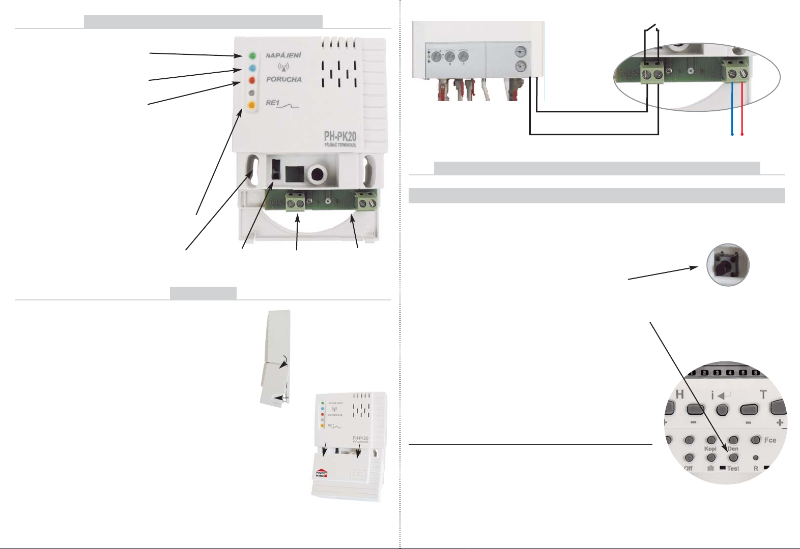
DESCRIPTION OF CONTROL ELEMENTS
START UP PROCEDURE IN THE PocketHome®SYSTEM
- check correct of receiver connection to boiler
and el. network
- push briefly FUNCTION SWITCH
for ca 1s (blue and red LED blinking intermittently)
- press ” Test ” in ACTIV mode for receiver on the
central unit (see instructions for PH-CJ37)
- for correct code learning blue and red LED blink
simultaneously
- during 1min. the receiver is activated in the
PocketHome system and is priority-controlled
from the PH-CJ37 central unit!
output clips
for boiler
power feed
clips
FUNCTION
SWITCH
Indication LED's:
GREEN LIT UP
- correct connection to el. network
BLUE BLINKING
- sending or receiving signal
RED BLINKING
- empty E-EPROM memory
RED LIT UP
- FAILURE (if no signal is received in ca 6
hours from the transmitter, will witch to 2
min. ON and 8 min. OFF regime)
BLUE+RED BLINKING ALTERNATELY
- code determination regime
BLUE+RED BLINKING CONCURRENTLY
- code was learnt
ORANGE LIT UP
- relay 1 switched on
MOUNTING
BOILER
We recommend that the installation should be carried out by person with
a relevant electro-technician's qualification!
- lift off front cover of receiver
according to figs 1,2
- attach receiver to wall (or directly to
installation box)
- turn off main switch
- connect according to chart (use clips
for room thermostat - 2 wires)
- connect receiver to 230V/50Hz
el. network
- zturn on main switch and green LED
will light up – receiver ready for further
setting.
installation holes
for KU/KP68
Before receiver activation it is necessary to have the central unit set and ready
according to instructions for PH-CJ37!
1. RECEIVER ACTIVATION -ESTABLISHING COMMUNICATION WITH THE CENTRAL UNIT
If communication is not successfully established:
- push FUNCTION BUTTON for 5s to delete
E-EPROM memory (RESET) (all LED's are lit
up and after 2s only red light start to blink –
empty memory)
- repeat the whole code-learning procedure
Fig.1
Fig.2
230 V/ 50 Hz
LN
ph_pk20_en:Layout 1 18.5.2011 21:25 Page 2
Other ELEKTROBOCK Receiver manuals


