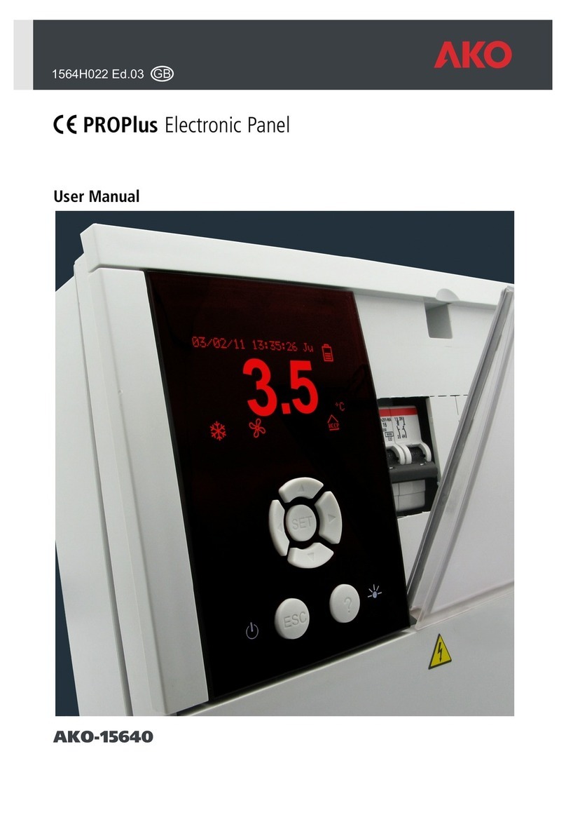
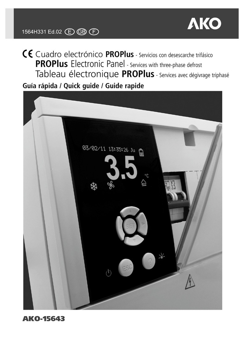
AKO PROPlus User manual

POWER SUPPLY
230V AC +10% -15%
50/60Hz ± 3Hz
CONNECT ALL EARTHING
IN THIS CONNECTOR
L
L
N
N
CONNECT THE BATTERY
GB
1564H002 Ed.04
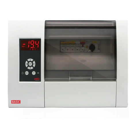
PROPlus electronic control panel
Electronic power control panel with a magneto-thermal protection cutout
switch for electrical control and operation of refrigeration services consis-
ting of a single-phase condensing unit, single-phase evaporator fans, sole-
noid valve, air or electric defrost (single phase), interior light and electrical
compressor sump heating resistance.
Incorporates graphic display, temperature register (1 channel), switch for in-
terior light, buzzer and relay alarm signal.
1- Warnings
Using the AKO-15640 without following the manufacturer’s instructions may alter its safety require-
ments.
To ensure correct operation of the apparatus, only NTC type probes supplied by AKO should be used.
Between –40 °C and +20 °C, when the probe is extended up to 1000 m with minimum 0,5 mm²
cable, deviation will be less than 0.25 °C (probe extension cable ref. AKO-15586)
2- Installation
The AKO-15640 should be installed in a place protected from vibrations, water and corrosive
gases, and where ambient temperature does not exceed the value specified in the technical data.
In order for the controllers to have IP65 protection degree, the gasket should be properly installed
between the apparatus and the perimeter of the panel cut-out where it is to be fitted.
In order to give a correct reading, the probe should be installed in a place without heat influences
other than the temperature that is to be measured or controlled.
2.1 Wall Mounting
- Remove cover T from the unit (Fig.1)
- Open the unit and separate the front part of the housing (Fig.2).
- Drill the holes for the glands required for the cables to pass through, guided by the pre-cut
centres in the sides of the housing.
- Drill 3 holes in the wall to match anchoring holes 1, 2 and 3 on the housing (Fig. 3).
- Insert the glands in the unit.
- Insert and tighten the 3 screws + plugs through the housing, into the 3 holes drilled in the wall.
- Pass the cable through the glands.
- Connect wiring specified on paragraph 2.3.1.
- Mount the front part on the housing (Fig.2).
- Insert and tighten screws D and F (Fig. 1).
- Connect wiring specified on paragraph 2.3.2.
- Close cover T, insert and tighten screws A and C (Fig. 1).
2.2 Panel Mounting (maximum panel thickness: 3mm)
- Remove cover T from the unit (Fig.1)
- Open the unit and separate the front part of the housing (Fig.2).
- Replace the seal installed at the front with the panelling seal, ensuring that it is in the right
position.
- Cut a hole in the panel with the described dimensions. (Fig.4)
- Drill the holes for the glands required for the cables to pass through, guided by the pre-cut
centres in the sides of the housing.
- Finish drilling holes G and J using a 4-mm bit. (Fig.3)
- Insert the glands in the unit.
- Pass the cable through the glands.
- Connect wiring specified on paragraph 2.3.1.
- Attach the front to the housing, through the panel and tighten the 45-mm screws through
holes D, E, F, G H, J (Fig.1 and Fig.3).
- Connect wiring specified on paragraph 2.3.2.
- Close cover T, insert and tighten screws A and C (Fig. 1).
2.3 Connection
CONNECT THE BATTERIES PRIOR TO STARTING UP THE UNIT
The probe and its lead should NEVER be installed in the same ducting as power or control cables.
Always disconnect the power supply when making the connections.
The power-supply circuit should be fitted with a main switch and residual current protection out-
side the panel.
Power supply cables should be H05VV-F 2x2.5 mm² or H05V-K 2x2.5 mm².
IMPORTANT: The function of every probe entry depends on its configuration (See ta-
ble “Assignment of entries”).
To obey EN12830 you must configure the control probe and the register probe seperatly.
2.3.1 Connect before closing the front part
2.3.2 Connect after closing the front part
WARNING: Be sure to disconnect mains power before performing any operation in
these terminal strips; connectors from 33 to 43 may contain voltage.
4- Front Panel Functions
Time and Battery: View time in format: YY/MM/DD HH:MM:SS day of the week configurable
in menu u (CLOCK)
View the status of the unit's battery:
f Battery flat e Battery charging d Battery charged
Temperatures: View the temperatures of the selected probes in °C or °F configurable in menu:
q (GENERAL STATUS)
Description: This allows a brief description of the facility to be entered or a name to be given
to the unit, configurable by pressing the SET + ►keys for 5 seconds.
Status: View the status of the functions performed by the control:
AKO-15640
222,1 mm
140 mm
222,1 mm
140 mm
214 mm
214 mm
FIG.4FIG.3
FIG.1
FIG.2
G COOL (Compressor)
Permanent: Cooling relay COOL
(compressor) activated.
Flashing: According to the temperature
detected by Probe 1, the COOL relay should be
activated, but is not due to a programmed
parameter.
X FAN
Permanent: FAN relay activated.
Flashing: According to the temperature
detected by Probe 2, the FAN relay should be
activated, but is not due to a programmed
parameter.
H DEFROST
Permanent: Indicates defrosting in
operation.
I DEFROST ENDED BY TIME
Permanent: Indicates last defrost ended by
time.
F CONTINUOUS CYCLE
Permanent: Indicates that the continuous
cycle is active.
R ALARM ON
Permanent: Alarm indicator activated.
T ALARM MUTED
Flashing: Alarm detected but signal
maintained. Alarm relay disconnected.
k LIGHTING
Permanent: LIGHT relay indicator activated
by key.
8A
Tr-
Tr+
RS-485
NC NO C
L N
ALARM
PARAMETER SERVER
CONNECTOR
411 2
HIGH
PRESSURE
SWITCH
LOW
PRESSURE
SWITCH
FAN
230V AC
2.2 A
LN
LN
NL
NL
SUMP HEATER
230V AC
70W
LIGHT
230V AC
460W
CONDENSING UNIT
230V AC
11.5 A
1,25 CV
SOLENOID
230V AC
460W
DEFROST ELECTRIC
ELEMENT
230V AC
11A
2500W
S3
S2
S1
21 22 23 24 25 26 27 28 29 30 31 32 33 34 35
12
36 37 38 39 40 41 42 43
Note: The specified current and power are the
maximum allowed working values.
PANEL
CUT-OUT
ESC key
Browser
Cover
? key
Status
ESC/
STAND-BY
key
Browser
?/HELP
key
Time and
Battery
Temperatures
Descripction
Screen
Overheating
cutout
- 1 -

Z ENERGY SAVING
Permanent: Indicates that energy saving
function is activated.
sHACCP (Hazard Analysis and Critical
Control Point)
Permanent: Indicates that HACCP function
is activated.
Flashing: HACCP alarm stored.
v/x AUX (Auxiliary)
Flashing: AUX relay activated by key.
v/o AUX (Auxiliary)
Flashing: AUX relay activated by digital input.
v/m AUX (Auxiliary)
Flashing: AUX relay indicating whether the
unit is connected or disconnected.
v/H AUX (Auxiliary)
Flashing: AUX relay operating as a second
defrosting device.
v/pAUX (Auxiliary)
Flashing: AUX relay operating as gas
collection valve.
UP key ù
H
- When pressed for 5 seconds, manual defrost
is activated/deactivated for the programmed
duration.
- In programming, it moves the selection up-
wards.
- In programming, it increases the programmed
value.
LEFT key ÿ
v
- Press to activate / deactivate the AUX relay.
- In programming, it moves the selection to the
left.
DOWN key ü
w
- When pressed for 5 seconds, the Set Point
temperature is displayed.
- In programming, it moves the selection down-
wards.
- In programming, it reduces the programmed
value.
RIGHT key ÷
F
- When pressed for 5 seconds, it acti-
vates/deactivates the CONTINUOUS CYCLE
for the programmed duration.
- Pressing for 5 seconds with the CONTINUOUS
CYCLE activated interrupts the process imme-
diately.
- In programming, it moves the selection to
the right.
SET key / PRG
- When pressed for 5 seconds the parameters
folder screen is displayed.
- In programming, it accepts the programmed
value.
ESC key / m
- Deactivates alarm but leaves signal active
(turns off acoustic alarm signal).
- When pressed for 5 seconds it turns the unit
off/on, leaving it in STAND-BY mode.
The display shows when the unit is discon-
m
nected.
- In programming, it exits a parameter with-
out saving changes, returns to the previous
menu and exits programming.
? key / k
- Turns lighting relay on/off. The lighting key
continues operating even if the unit is in
STAND-BY mode.
- In programming, it displays the parameter
or selected function help screen.
3.1 Browser
Pressing any key on the browser brings up the key function help screen:
SET + ù (CONTRAST) keys
- When pressed for 5 seconds, the screen con-
trast can be adjusted. Once in the contrast ad-
justment screen, press ù or ü to increase or
reduce the contrast.
SET + ÿ (HACCP) keys
- When pressed for 5 seconds, the HACCP (Haz-
ard Analysis and Critical Control Point) events
register is accessed.
SET + ÷ (DESCRIPTION) keys
- When pressed for at least 5 seconds, it per-
mits the user to enter a brief description of
the facility or give a name to the unit. To edit
the description, select the character to be en-
tered using the browser keys and press SET.
Press the ÷ key to move the character to be
entered to the right and ÿ to move it to the
left.
Select the 9 key to erase a character that
has been incorrectly entered.
Press 8 to save the description.
ÿ + ÷ (REGISTER) keys
- When pressed for 5 seconds, the data register
is accessed.
- The record stores the information inside 366
blocks of 96 information records each block.
There must be at least one probe configura-
ted as record probe (see table “Assignment
of entries”)
- Select the desired block using the browser
keys. The block is selected by *.
- Press the ÷ key to add the block to be dis-
played to the selection.
- Press the ÿ key to eliminate the block that is
not required to be displayed from the selection.
- Press the SET key to accept the block selection.
Notes: Only consecutive blocks with the same register interval can be selected (maximum of 7).
The register interval is configured using the parameters menu, q specifically, the Recorder
Frequency parameter.
- Select 7 to view the 96 data registers.
- Select to view the graph of the 96 data registers.
4
4- Adjustment and Configuration
This should only be performed by personnel with knowledge of the unit's operation and limita-
tions.
4.1 Set Point temperature.
The factory SET POINT default value is 0.0 °C.
- Press the ü key for 5 seconds to display SET POINT.
- Press the browser keys to change the Set Point to the re-
quired value.
- Press the SET key to accept the new Set Point. The dis-
play returns to the current temperature display status.
If PASSWORD appears, enter the access code (password) programmed in the ACCESS CODE pa-
rameter of the menu to access the current set point.
q
- Press the browser keys to enter the programmed code (Password).
- Press the SET key to accept the code. The current SET POINT value will be displayed and can be al-
ready modified.
4.2 Parameter configuration
Level 1 Menus
- Press the SET key for 5 seconds to view the MENUS.
- Press the browser keys to select the menu.
- Press the SET key to access the parameters of the
selected menu.
If PASSWORD appears, enter the access code (pass-
word) programmed in the ACCESS CODE parameter
of the menu to access the current set point.
q
- Press the browser keys to enter the programmed
code (Password).
- Press the SET key to accept the code. The menus that can be modified are displayed.
Level 2 Parameters
- In the desired menu of level 1 MENUS, press SET key. Level 2 PARAMETERS programming is ac-
cessed. The first parameter of the selected menu is
displayed on the screen.
- Press the browser keys to select the parameter.
Level 3 Values
- To display the current value of any parameter, se-
lect the required parameter and press SET key.
Once it is displayed, press the browser keys to
change the value.
- Press SET key to accept the new value. The pro-
gramming returns to LEVEL 2 PARAMETERS.
NOTE: If no key is pressed for 25 seconds in either
of the previous steps, the controller will automati-
cally return to the CURRENT TEMPERATURE dis-
play status without modifying any of the parame-
ters values.
Keys
browser
Help
function
keys
Combinations of
browser keys
Description of event
Date and time
of event
Power
failure
Duration
of event
in hours Maximum
temperature
value
Recording
event
Date of
register block
(yy/mm/dd)
Time of
register block
(hh:mm)
Register
interval
(minutes)
Register block
selection
No. of
registers
Date of
register
(yy/mm/dd)
Time of
register
(hh:mm)
Register
value
in °C or °F
Date/time
1st register
Register
interval
Block no.
Date/time
last register
=
=
=
Max.
value
Current
value
Min.
value
Current
set point
Menus
Description of selected menu
Max.
value
Current
value
Min.
value
Current
set point
Parameter
- 2 -

5- Description of Parameters and Messages
Values in the Def. column are factory-set.
NOTE: When time parameters are modified, the new values are applied when the current cycle
is completed. To apply values immediately, switch the controller off and then on again.
Level 3 Description Values Mín. Def. Máx.
Level 2 DEFROST control
Level 3 Description Values Mín. Def. Máx.
Set temperature (SP) (no locks)
Probe 1 differential (Hysteresis)
Set Point upper limit
(It cannot be set above this value)
Set Point lower limit
(It cannot be set below this value)
Compressor protection delay type:
OFF/ON (From the last switch-off)
ON (At switch-on)
Compressor protection
delay time.
“COOL” (Compressor) relay time in ON
in event of faulty probe 1
(If 0, the relay is always OFF)
“COOL” (Compressor) relay time in OFF
in event of faulty probe 1
(If 0, the relay is always ON)
Compressor stops when opening door?
(NO= connected) (YES=disconnected)
(ºC/ºF)
(ºC/ºF)
(ºC/ºF)
(min.)
(ºC/ºF)
(min.)
(min.)
-40.0 0.0 320
0.1 1.0 20.0
-40.0 99.9 320
-40.0 -40.0 320
off/on off/on on
0 0 255
0 10 255
0 5 255
No No Yes
EH
Defrost type:
(Electrical heater) (Hot gas by-pass)
Message maximum duration
Time added at the end of defrost (min.) 0 5 255
Defrost final temperature on probe 2
If probe 2 is programmed
Defrost start-up on equipment switch-on:
Defrost start-up delay on equipment
switch-on
Signals if defrost ends due to maximum time
Drip time, compressor stops and FAN
relay off when defrost ends
(ºC/ºF) -40.0 8.0 99.9
No No Yes
(min.) 00255
No No Yes
(min.) 01255
Fre.
06120
030 255
Def.
Defrost count
(Frequency)
(Compressor operation sum)
(RTC: Real time clock)
Defrost frequency:
Elapsed time between 2 starts
Defrost maximum duration
Type of message during defrost:
(Current temperature display)
(Defrost start temperature display)
(Display DEFROST message)
Level 2 ALARM control (Visual)
Level 2 DIGITAL INPUTS
Level 3 Description Values Mín. Def. Máx.
Probe 2 differential
Stop fans when compressor stops?
(NO= connected) (YES=disconnected)
Fans status during defrost
(Connected) (Disconnected)
Start-up delay after defrost
Operates if it is higher than Drip Time
Configuration of temperature alarms
(Relative to SP) (Absolute)
Stop fans if the door opens?
(No=Connected) (Yes=Disconnected)
Maximum alarm in probe 1
Minimum alarm in probe 1
Temperature Alarms Differential
Temperature alarm delay from moment at
which they should operate due to temperature
Temperature alarm delay
on start-up
Temperature alarm delay from
the end of a defrost
Temperature alarm delay from
digital input disabling
If programmed as “Door contact”
Temperature alarm delay from
digital input enabling
If programmed as “Door contact”
Alarm relay status
(Connected) (Disconnected)
Digital Input Nº1 configuration
(Disabled) (Door Contact)
(External alarm) (Severe external alarm)
(Remote defrost) (Remote Energy saving)
(AUX relay activation) (Low-pressure in)
Alarm delay of digital input N°1
(ºC/ºF) 0.1 1.0 20.0
No No Yes
Disc.
(min.) 03255
No No Yes
Rel.
(ºC/ºF) -40.0 50.0 320
(ºC/ºF) 0.1 1.0 20.0
(min.) 030 255
(min.) 00255
(min.) 0 0 255
(min.) 0 0 255
(min.) 0 0 255
Conn.
Dis.
(min.) 0 0 255
Level 3 Description Values Mín. Def. Máx.
Fans stop temperature by
probe 2. If probe 2 is programmed (ºC/ºF) -40.0 4.0 99.9
Level 2 FANS control (Evaporator)
Level 1 Menus and Description
Level 2 REFRIGERATION control (Compressor)
Level 2 AUX RELAY
Level 2 GENERAL STATUS
Level 3 Description Values Mín. Def. Máx.
Polarity of digital input Nº1
(Normally open) (Normally closed)
Digital input N°2 configuration
(Disabled) (Door Contact)
(External alarm) (Severe external alarm)
(Remote defrost) (Remote Energy saving)
(AUX relay activation) (Low-pressure in)
Alarm delay of digital input N°2
Polarity of digital input Nº2
(Normally open) (Normally closed)
AUX relay configuration
(Disabled) (Activated by key)
(Activated by input) (Equal state of equipment)
(Second Defrost) (Pump down control)
Defrost 2 probe
(Disabled) (Probe 2) (Probe 3)
Defrost 2 maximum duration
Defrost 2 final temperature
Pump-down duration
Pump-down On delay
Access code (password) to
parameters and set point
NC.
Dis.
Dis.
Dis.
NC.
(min.) 0 0 255
(min.) 0 30 255
(sec.) 1180 1800
(sec.) 0 5 60
0099
Level 2 CONTINUOUS CYCLE
Level 3 Description Values Mín. Def. Máx.
(min.) 00255
Display mode (1 probe + clock) (1 probe + text)
(Connected probes + clock + text)
Temperature display unit
Decimal point
Delay of all functions on power supply switch on
Type of operation:
Not selectable (always cold)
Program version (Information)
Continuous cycle duration
Yes
ºC ºC ºF
Cold
(h.) 0 1 24
1PC
Allocation of password to Set Point
Initial parameters:
(YES, configure in “Def” and exit programming)
Register interval
Address for units with communication
Parameters transfer
(Disabled) (Send) (Receive)
Connected probes (Probe 1), (Probe 1 and 2)
(Probe 1 and 3) (Probe 1, 2 and 3)
Probe to be displayed
Dis.
No
No
01 255
(min.) 015 60
1 1 3
1
Level 2 ENERGY SAVING
Level 3 Description Values Mín. Def. Máx.
Level 2 HACCP
Level 3 Description Values Mín. Def. Máx.
Level 2 LANGUAGE
Level 3 Description Values Mín. Def. Máx.
Level 2 CLOCK
Level 3 Description Values Mín. Def. Máx.
Set Point during
energy saving
Duration of energy saving
Delay in registering a event after a temperature alarm
English
Date (Year Month Day)
Time (Week_Day Hour Minute)
Defrost 1 (Day Hour Minute)
Defrost 2 (Day Hour Minute)
Defrost 3 (Day Hour Minute)
Defrost 4 (Day Hour Minute)
Defrost 5 (Day Hour Minute)
Defrost 6 (Day Hour Minute)
Defrost 7 (Day Hour Minute)
Defrost 8 (Day Hour Minute)
Energy saving Start (Day Hour Minute)
(min.) 0 255
(h.) 0024
(ºC/ºF) -40.0 0320
0
-58.0 8.0 99.9
Probe setting (TEM at S1/REG at S3),
(TEM and REG at S3) (See table “Assignment of entries”) TEM
at S1
- 3 -
Access code (password) request to enter programming of parameters or Set Point
Indicates defrosting is in progress.
Flashing with temperature
Flashing with temperature - Temperature of Probe 1 exceeds maximum Probe 1
Alarm parameter.
Flashing with temperature - Temperature of Probe 1 is below minimum
programmed Probe 1 Alarm parameter.
Flashing with temperature - Low-pressure pressostat error with compressor in
operation.
Probe 1, 2 or 3 failure (Open, crossed circuit; NTC: temp.> 110 ºC
or temp.<-55 ºC; PTC: temp.> 150 °C or temp.<-58 °C)
MESSAGES
ACCESS CODE
DEFROST
EXTERNAL ALARM
HIGH TEMP. ALARM
SEVERE EXT. ALARM
LOW TEMP. ALARM
LOW PRESSURE ALARM
PROBE 1, 2, or 3 ALARM
6- Accessories
PORTABLE SERVER
AKO-14918 portable server, with no power supply, in
which parameters programmed in a powered controller
can be copied by transfer. Parameters can be transferred
again from the server to other identical powered
controllers.
COMMUNICATIONS
The units provided with a communications connector,
permit data transmision and reception using the
standard MODBUS protocol and to carry out
management from PC software. This makes a
centralised system for display, logging, alarms, remote
teleprocessin…
AKO-5004
Software for controllers and data loggers using a PC type computer.
7- Maintenance
Clean the controller surface with a soft cloth, soap and water. Do not use abrasive detergents,
petrol, alcohol or solvents.
Equipment including rechargeable electrical batteries:
This unit includes batteries which must be replaced when the device’s autonomy
time is below the indicated in the specifications. At the end of the unit’s service life.
the batteries should be disposed of at a selective refuse collection site or returned
tot he manufacturer.
8- Technical Data
Power. . . . . . . . . . . . . . . . . . . . . . . . . . . . . . . . . . . 230V AC +10% -15% 50/60Hz ± 3Hz
Maximum total intensity . . . . . . . . . . . . . . . . . . . . . . . . . . . . . . . . . . . . . . . . . . . . . . . . 16A
Relay features (check maximum authorised working current)
COMPRESSOR Relay . . . . . . . . . . . . . . . . . . . . . . . . . . . . . . . . . 20A to 250V, cosj =1
AUX Relay . . . . . . . . . . . . . . . . . . . . . . . . . . . . . . . . . . . . . . . . 16A to 250V, cosj =1
LIGHT Relay . . . . . . . . . . . . . . . . . . . . . . . . . . . . . . . . . . . . . . . 16A to 250V, cosj =1
FAN Relay. . . . . . . . . . . . . . . . . . . . . . . . . . . . . . . . . . . . . . . . . . 8A to 250V, cosj =1
DEFROST Relay. . . . . . . . . . . . . . . . . . . . . . . . . . . . . . . . . . . . . 30A to 250V, cosj =1
ALARM Relay . . . . . . . . . . . . . . . . . . . . . . . . . . . . . . . . . . . . . . . 8A to 250V, cosj =1
Temperature range of the probe . . . . . . . . . . . . . . . . . . . . . . . . . . . . . . . -40.0 ºC to 99.9 ºC
Resolution, Set Point and differential . . . . . . . . . . . . . . . . . . . . . . . . . . . . . . . . . . . . . 0,1 ºC
Thermometric accuracy . . . . . . . . . . . . . . . . . . . . . . ± 1 ºC as per EN 12830 and EN 13485
Denomination . . . . . EN 12830, S, A, 1, -40 ºC +40 ºC; EN 13485, S, A, 1, -40 ºC +40 ºC
Probe tolerance at 25 ºC (NTC) . . . . . . . . . . . . . . . . . . . . . . . . . . . . . . . . . . . . . . . ± 0,4 ºC
Input for NTC probe . . . . . . . . . . . . . . . . . . . . . . . . . . . . . . . . . . . . . . . . . . . . . AKO-149XX
Maximum input power. . . . . . . . . . . . . . . . . . . . . . . . . . . . . . . . . . . . . . . . . . . . . . . . 24 VA
Working ambient temperature . . . . . . . . . . . . . . . . . . . . . . . . . . . . . . . . . . . . . 0 ºC to 50 ºC
Ambient storage temperature . . . . . . . . . . . . . . . . . . . . . . . . . . . . . . . . . . . . -30 ºC to 70 ºC
Installation category. . . . . . . . . . . . . . . . . . . . . . . . . . . . . . . . . . . . . . . II as per EN 61010-1
Pollution degree. . . . . . . . . . . . . . . . . . . . . . . . . . . . . . . . . . . . . . . . . . II as per EN 61010-1
Double insulation between the power supply, the secondary circuit and the relay output.
Recorder autonomy in the event of a power failure . . . . . . . . . . . . . . . . . . . . . . . . . 48 Hours
Battery . . . . . . . . . . . . . . . . . . . . . . . . . . . . . . . . . . . . . . . . . . . . . . . Li-Polymer for recorder
Internal buzzer
9- Mounting warnings and electrical diagrams
WARNING!!
Disconnect mains power before performing any operation inside the electric panel.
All wiring must comply with the regulations in force and must be performed by authorized
personnel.
Perform only the connections described in the electrical diagrams.
Use of the electrical panel contrary to the manufacturer's instructions may affect its safety
requirements.
Working ambient temperature: 0 ºC to + 50 ºC
Assigned insulation voltage Ui = 440 V~
Electric panels with IP65 protection degree
CEM 1 environment
Connectors for copper conductors
Resistance to short circuits Isc=4,5 kA
Panel installation:
Do not knock or perform rough movements in the panel.
Perform connections according to installation manual.
The probe and its lead should NEVER be installed in the same ducting as power or control
cables.
The earth connectors in the panels are installed to ensure continuity of the earth connection;
however, the earth connection is not made by the connector and should be made outside the
panel.
The neutral systems are TT or TNS type. The IT system cannot be used. The magneto-thermal
protection cutout switches are phase/s + neutral, C curve, ensuring sectioning and protection
against voltage spikes.
Close panel when not working on it.
Connection of main switch and residual current protection outside the electric panel as per the
electrotechnical regulations for low voltage.
Verifications before panel start-up:
The power voltages and frequencies must be those shown in the table and diagram
corresponding to each panel model.
Check that there are no loose parts or foreign bodies on the connections or components.
Check that there is no dust or moisture inside the panel.
Check that all components are properly fastened.
Check that power connection screws are properly tightened.
Check that power conductors are properly connected.
Check that outside lines are properly insulated and do not exert mechanical force on the
connections inside the panel.
Verifications during panel start-up:
Check that electric arcing does not occur.
Check that relays and contacts do not produce rattles
Check that cables, controllers and the rest of the unit do not overheat.
Verification after first 24 hours of operation:
Check that overheating does not occur.
Tighten screws and power connections.
Periodic preventive maintenance:
The panel should always be kept closed using the fasteners.
Tighten power connections annually.
Check for wear of the unit annually.
Clean the panel outside surface with a soft cloth, soap and water.
Do not use abrasive detergents, petrol, alcohol or solvents.
AKO-14918
Transfer
PROPlus
ESC ?
SET
Power supply
Programming
AKO ELECTROMECÀNICA, S.A.L.
We reserve the right to supply materials that might vary slightly to those described in our
Technical Sheets. Updated information is available on our website: www.ako.com
Av. Roquetes, 30-38 | 08812 Sant Pere de Ribes | Barcelona | España
Tel. (34) 938 142 700 | Fax (34) 938 934 054 | e-mail: [email protected] |
Apartado (P.O. Box), 5 | 08800 Vilanova i la Geltrú | Barcelona | España
www.ako.com
351564002 REV.03 2010
ASSIGNMENT OF ENTRIES ACCORDING TO CONFIG. OF PROBE
PROBE CONFIGURATION
TEM at S1/REG at S3 (According to EN12830)
Connectors
Probe 1
Control, alarms and HACCP probe
Input S1
21 and 24
Probe 2
Defrost probe (or 2º defrost)
Input S2
21 and 23
Probe 3
Registry probe (or 2º defrost)
Input S3
21 and 22
TEM+REG at S3
Connectors
Probe 1
Control, alarms, HACCP and registry probe
Input S3
21 and 22
Probe 2
Defrost probe (or 2º defrost)
Input S2
21 and 23
Probe 3
Product core probe (or 2º defrost)
Input S1
21 and 24
Other manuals for PROPlus
1
This manual suits for next models
1
Other AKO Control Panel manuals

AKO
AKO PROPlus 3PH Series User manual

AKO
AKO PROPlus User manual

AKO
AKO PROCool AKO-17635-1 User manual

AKO
AKO PROPlus AKO-1565 Series User manual

AKO
AKO PROCool AKO-17632 User manual

AKO
AKO AKO-15690 User manual

AKO
AKO PROPlus 3PH Series User manual

AKO
AKO 15640 User manual

AKO
AKO AKO-17630 User manual

AKO
AKO PROPlus 3PH Series User manual