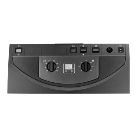
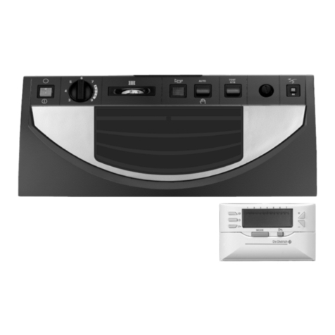
DeDietrich IniControl Troubleshooting guide

Ireland
EN
Regulation
IniControl
For C 330 / C 630 ECO
C003108-A
Installation, User
and Service
Manual
7600717-001-06

Contents
1 Introduction ................................................................................................4
1.1 Symbols used .......................................................4
1.2 Liabilities ...............................................................4
1.2.1 Manufacturer’s liability .............................................4
1.2.2 Installer’s liability .....................................................5
1.2.3 User’s liability ..........................................................5
1.3 Certifications .........................................................6
2Safety instructions and recommendations ..............................................7
2.1 Recommendations ................................................7
3Technical specifications ............................................................................8
3.1 Sensor characteristics .........................................8
4Installation ..................................................................................................9
4.1 Package list ...........................................................9
4.1.1 Standard delivery ....................................................9
4.1.2 Accessories .............................................................9
4.2 Installing the outside sensor ...............................9
4.2.1 Choice of the location ..............................................9
4.2.2 Connecting the outside sensor ..............................10
4.3 Fitting and connecting the control panel .........10
4.4 Electrical connections ........................................11
4.4.1 Connecting a direct heating circuit ........................11
4.4.2 Connection in cascade (with OpenTherm AD287)
option ....................................................................11
5 Commissioning ........................................................................................13
5.1 Control panel .......................................................13
5.1.1 Description of the keys ..........................................13
5.1.2 Description of the display ......................................14
5.2 Switch on the instrument panel ........................15
5.3 Reading out measured values ...........................16
5.3.1 Reading out measured values ..............................16
5.3.2 Readout from the hour counter and percentage of
successful starts ....................................................17
5.3.3 Status and sub-status ...........................................18
1260216 - 7600717-001-06
5.4 Changing the settings ........................................19
5.4.1 General .................................................................19
5.4.2 Parameter descriptions .........................................19
5.4.3 Modification of the user-level parameters .............23
5.4.4 Modification of the installer-level parameters ........24
5.4.5 Setting the maximum heat input for central heating
operation ...............................................................25
5.4.6 Return to the factory settings Reset Param ..........26
5.4.7 Carrying out an auto-detect ...................................26
5.4.8 Setting the manual mode ......................................27
6 Troubleshooting .......................................................................................28
6.1 Shutdowns and lock-outs ..................................28
6.1.1 General .................................................................28
6.2 Error memory ......................................................35
6.2.1 Error readout memorised ......................................35
6.2.2 Deletion of the error display ..................................36
Contents
2260216 - 7600717-001-06

3260216 - 7600717-001-06

1 Introduction
1.1 Symbols used
In these instructions, various danger levels are employed
to draw the user’s attention to particular information. In so
doing, we wish to safeguard the user’s safety, highlight
hazards and guarantee correct operation of the appliance.
DANGER
Risk of a dangerous situation causing serious
physical injury.
WARNING
Risk of a dangerous situation causing slight
physical injury.
CAUTION
Risk of material damage.
Signals important information.
¼Signals a referral to other instructions or other pages
in the instructions.
1.2 Liabilities
1.2.1. Manufacturer’s liability
Our products are manufactured in compliance with the
requirements of the various applicable European
Directives. They are therefore delivered with [ marking
and all relevant documentation.
IniControl For C 330 / C 630 ECO 1. Introduction
260216 - 7600717-001-06 4

In the interest of customers, we are continuously
endeavouring to make improvements in product quality.
All the specifications stated in this document are therefore
subject to change without notice.
Our liability as the manufacturer may not be invoked in the
following cases:
4Failure to abide by the instructions on using the
appliance.
4Faulty or insufficient maintenance of the appliance.
4Failure to abide by the instructions on installing the
appliance.
1.2.2. Installer’s liability
The installer is responsible for the installation and
commissioning of the appliance. The installer must
respect the following instructions:
4Read and follow the instructions given in the manuals
provided with the appliance.
4Carry out installation in compliance with the prevailing
legislation and standards.
4Perform the initial start up and carry out any checks
necessary.
4Explain the installation to the user.
4If a maintenance is necessary, warn the user of the
obligation to check the appliance and maintain it in
good working order.
4Give all the instruction manuals to the user.
1.2.3. User’s liability
To guarantee optimum operation of the appliance, the
user must respect the following instructions:
4Read and follow the instructions given in the manuals
provided with the appliance.
4Call on qualified professionals to carry out installation
and initial start up.
4Get your installer to explain your installation to you.
4Ensure the Appliance is serviced in accordance with
the manufacturer’s instructions by a suitable qualified
person.
4Keep the instruction manuals in good condition close
to the appliance.
1. Introduction IniControl For C 330 / C 630 ECO
5260216 - 7600717-001-06

This appliance is not intended to be used by persons
(including children) whose physcial, sensory or mental
capacity is impaired or persons with no experience or
knowledge, unless they have the benefit, through the
intermediary of a person responsible for their safety, of
supervision or prior instructions regarding use of the
appliance. Care should be taken to ensure that children
do not play with the appliance.
If the mains power lead is damaged it must be replaced
by the original manufacturer, the manufacturer’s dealer or
another competent person to prevent hazardous
situations.
1.3 Certifications
This product complies to the requirements to the
european directives and following standards:
42006/95/EC Low Voltage Directive. Reference
Standard: EN60.335.1.
42004/108/EC Electromagnetic Compatibility Directive.
Generic standards: EN1000-6-3 , EN 61000-6-1.
IniControl For C 330 / C 630 ECO 1. Introduction
260216 - 7600717-001-06 6

2 Safety instructions and
recommendations
2.1 Recommendations
WARNING
Any intervention on the appliance and heating equipment
must be carried out by a qualified engineer.
For a proper operating of the boiler, follow carefully the
instructions.
Keep this document close to the place where the boiler is
installed.
2. Safety instructions and recommendations IniControl For C 330 / C 630 ECO
7260216 - 7600717-001-06

3 Technical specifications
3.1 Sensor characteristics
Outside sensor
Temperature in °C -20 -16 -12 -8 -4 0 4 8 12 16 20 24
Resistance in Ω 2392 2088 1811 1562 1342 1149 984 842 720 616 528 454
Specifications of the flow sensor circuit B + C
Specifications of the DHW sensor
Specifications of the system sensor
Temperature in °C 0 10 20 25 30 40 50 60 70 80 90
Resistance in Ω 32014 19691 12474 10000 8080 5372 3661 2535 1794 1290 941
IniControl For C 330 / C 630 ECO 3. Technical specifications
260216 - 7600717-001-06 8

4 Installation
4.1 Package list
4.1.1. Standard delivery
The delivery includes:
4The control panel with the IniControl module
4Installation, use and maintenance manual for the control panel
4.1.2. Accessories
Various options are available depending on the configuration of the
installation:
Control system options
Description package
BUS connection cable (length 12 m) AD134
voice remote monitoring module AD152
OpenTherm interface AD287
Outside sensor FM46
RX11 cable AD124
Modulating room thermostat AD265
Radio-controlled modulating room thermostat AD266
Digital room thermostat AD137
Wireless settable ambient thermostat AD200
SCU-S05 PCB
SCU-S03 PCB
4.2 Installing the outside sensor
4.2.1. Choice of the location
It is important to select a place that allows the sensor to measure the
outside conditions correctly and effectively.
Advised positions:
4on one face of the area to be heated, on the north if possible
4half way up the wall in the room to be heated
4under the influence of meteorological variations
4. Installation IniControl For C 330 / C 630 ECO
9260216 - 7600717-001-06

4protected from direct sunlight
4easy to access
ARecommended position
BPossible position
HInhabited height controlled by the sensor
ZInhabited area controlled by the sensor
Positions to be avoided:
4masked by a building element (balcony, roof, etc.)
4close to a disruptive heat source (sun, chimney, ventilation grid,
etc.)
4.2.2. Connecting the outside sensor
Mount the sensor using the screws and dowels provided.
AInserts
ZØ4 wood screw
¼For the connection of the outside temperature sensor, refer to
the chapter "Electrical Connections".
4.3 Fitting and connecting the control panel
¼Refer to the boiler’s installation and service manual.
8800N001-C
8800N002-C
8800N003-C
2
IniControl For C 330 / C 630 ECO 4. Installation
260216 - 7600717-001-06 10

4.4 Electrical connections
4.4.1. Connecting a direct heating circuit
AConnect the outside temperature sensor.
SCU-S05 PCB = Option
ZHeating connection pump.
EConnect a safety thermostat if the heating circuit is for
underfloor heating.
4Remove the bridge.
4Connect the wires from the safety thermostat to the
connector.
4.4.2. Connection in cascade (with OpenTherm
AD287) option
AMaster boiler (DIEMATIC iSystem)
ZSecondary boiler (DIEMATIC iSystem or IniControl)
ESecondary boiler (DIEMATIC iSystem or IniControl)
RCable BUS
M002709-C
1
3
2
On/off
OT
BL
RL
PCU
SCU-S05
PUMP
ECS S EXT S DE
2 1 21
M002710-C
5
6
7
8
9
0
1
2
3
4
6
7
8
5
12
44
3
On/off
OT
BL
RL
PCU
PUMP
OTH / MB
INTERFACE
OTH
9
10
11
12 13
4. Installation IniControl For C 330 / C 630 ECO
11 260216 - 7600717-001-06

TBoiler pump
YLow loss header
UCascade outlet sensor
Connect the sensor to the terminal block S SYST on the
master boiler.
IBoiler power supply - 230 V
OConnection cable linking the Opentherm from the PCU to
the Opentherm on the interface
POpenTherm (AD287) interface board to be fitted in the
boiler control panel
aEncoding wheel used to set the addresses of the slave
boilers. Set to 1 on boiler 2 - Set to 2 on boiler 3 - etc.
zBUS cable to the master boiler
eBUS cable to the slave boilers
IniControl For C 330 / C 630 ECO 4. Installation
260216 - 7600717-001-06 12

5 Commissioning
5.1 Control panel
For operation of the boiler C 630 ECO: Each module has
its own instrument panel.
5.1.1. Description of the keys
AReturn button j, Escape G or Manual reset t
BHeating temperature button d or [-]
CDHW temperature button r or [+]
DS [Enter] Key
E) [Chimney-sweeping] keys
Press keys A and B simultaneously
Ff [Menu] keys
Press keys C and D simultaneously
-
)
L
m
r
r
r
d
d
d
T
y
1
2
SERVICE
°C°Fh
barPsi
% rpm
kW uA
x10 l/min
°CSt:
M002715-A
t
h
j
A B
E F
C D
5. Commissioning IniControl For C 330 / C 630 ECO
13 260216 - 7600717-001-06

5.1.2. Description of the display
nKey functions
GBack to the previous level without saving the
modifications made
tManual reset
dCentral heating function:
Access to the max. heating temperature parameter.
[-] To reduce a value
rDHW function:
Access to sanitary hot water temperature parameter.
[+] To increase a value
®Access the selected menu or confirm a value modification
nOperating modes
dState heating pump
DHeating programme deactivated:
The heating function is deactivated
rState DHW pump
SDHW off
mManual mode
mThe DHW function is in economic mode (deactivated)
gBoiler protection is active
nFlame output level
eLow output level 0 - 25 %
rAverage output level 25 - 50 %
tHigh output level 50 - 75 %
yOutput level 75 - 100 %
-
)
L
m
r
r
r
d
d
d
T
y
1
2
SERVICE
°C°Fh
barPsi
% rpm
kW uA
x10 l/min
°CSt:
M002716-A
t
h
j
-
)
L
m
r
r
r
d
d
d
T
y
1
2
SERVICE
°C°Fh
barPsi
% rpm
kW uA
x10 l/min
°CSt:
M002717-A
t
h
j
-
)
L
m
m
r
r
d
d
d
T
y
g1
2
SERVICE
°C°Fh
barPsi
% rpm
kW uA
x10 l/min
°CSt:
M002735-A
t
h
j
-
)
L
m
r
r
r
d
d
d
T
y
1
2
SERVICE
°C°Fh
barPsi
% rpm
kW uA
x10 l/min
°CSt:
M002719-A
t
h
j
IniControl For C 330 / C 630 ECO 5. Commissioning
260216 - 7600717-001-06 14

nSystem pressure
bar Pressure indicator:
The symbol is displayed next to the installation’s pressure
value. If no water pressure sensor is connected, -.-
appears on the display
nOther information
"User menu:
Parameters at user level can be changed
!Information menu:
Reading the various current values
)Chimney-sweeping position:
Forced full or part load for CO2 measurement
-Service menu:
Parameters at installer level can be changed
KDisplay with the symbols:
$ + K + Z (Maintenance message)
\Hour counter menu:
Readout of the operating hours, number of successful
starts and hours on mains supply
aBlocking:
After 5 resets in under 1 hour, the appliance should be
switched off and switched on again before resetting
IOutside temperature sensor present
MThe symbol is displayed when the boiler pump is
operating
aDefect:
Boiler indicates a fault. This is indicated by an E code
and a flashing display
5.2 Switch on the instrument panel
For operation of the boiler C630 Eco: The features and
instructions described are for each boiler module.
The instrument panel IniControl is ready for use, as soon as the
power to the boiler is switched on.
1. Open the gas valve on the boiler.
2. Turn on the boiler using the on/off switch.
3. Set the controls (thermostats, control system) so that they request
heat.
-
)
L
m
r
r
r
d
d
d
T
y
1
2
SERVICE
°C°Fh
barPsi
% rpm
kW uA
x10 l/min
°CSt:
M002720-A
t
h
j
-
)
L
m
r
r
r
d
d
d
T
y
1
2
SERVICE
°C°Fh
barPsi
% rpm
kW uA
x10 l/min
°CSt:
M002721-A
t
h
j
5. Commissioning IniControl For C 330 / C 630 ECO
15 260216 - 7600717-001-06

4. The start-up cycle begins and cannot be interrupted. During the
start-up cycle, the display shows the following information:
A short test where all segments of the display are visible.
fK[xx: Software version
pK[xx: Parameter version
The version numbers are displayed alternately.
By pressing the S key for a short time, the current operating status
is shown on the display:
Heat demand Heat demand stopped
1: Fan ON 5: Burner stop
": Boiler is igniting 6: Post-circulation of the pump
3: Heating System 0: Standby
In STAND-BY, the display normally shows the water pressure next to
0 (only when the hydraulic pressure sensor is connected) and the
symbols d and H.
Error during the start-up procedure:
4No information is shown on the display:
-Check the mains supply voltage
-Check the main fuses
-Check the fuses on the control panel:
(F1 = 2 AT, F2 = 8 AT)
-Check the connection of the mains lead to the connector in the
instrument box
4A fault is indicated on the display by the fault symbol a and a
flashing fault code.
-The meaning of the error codes is given in the error table.
-Press for 3 seconds on key J to restart the boiler.
5.3 Reading out measured values
For operation of the boiler C630 Eco: The features and
instructions described are for each boiler module.
5.3.1. Reading out measured values
The following current values can be read off the information menu
Q:
45200 = Fan speed.
45201 = Fan speed Set point.
45203 = Burner flame signal.
45204 = Gas valve open (1) or closed (0).
45205 = GpS connected.
45206 = Ignition phase.
45207 = Ionization current.
45208 = Heat output requested.
45209 = Release input.
IniControl For C 330 / C 630 ECO 5. Commissioning
260216 - 7600717-001-06 16

45210 = Pressure switch minimum VPS.
45213 = Burner start.
45214 = Trap protection activated.
45215 = internal.
45216 = internal.
45217 = internal.
45218 = internal.
45219 = internal.
45220 = internal.
45226 = Heat output (Gvc).
45241 = State.
45242 = Sub-status.
45244 = Flow temperature.
45245 = Exchanger temperature.
45246 = Return temperature.
45247 = Water pressure.
45251 = Outside temperature (Only if an outside temperature
sensor is connected).
45252 = Inlet 0-10 Volts.
45256 = Internal set point (°C).
5.3.2. Readout from the hour counter and
percentage of successful starts
1. Press the two keys f simultaneously and then key [+] until the
symbol \ flashes on the menu bar.
2. Press the S key. hr and the number of hours of boiler
operation 3600 (for example) are displayed alternately.
3. Press the [+] key. The display shows D. hr is displayed,
alternating with the number of operating hours in central heating
operation 560 (for example).
4. Press the [+] key. The display shows @. 5Z is displayed,
alternating with the percentage of successful starts 92 % (for
example).
5. Press the j key 2 times to return to the current operating mode.
C003058-A
r
h
j
d
y
5x
2x
5. Commissioning IniControl For C 330 / C 630 ECO
17 260216 - 7600717-001-06

5.3.3. Status and sub-status
The information menu Q gives the following status and sub-status
numbers:
St status Sub-status Operation
0 Rest 0 Rest
1 Boiler start (Heat demand)
1 Anti-short cycle activated
2 Open isolating valve
3 Start-up of the boiler pump
4 Wait for the correct temperatures for burner start
2 Burner start
10 Open gas valve (External)
11 Fan start-up
12 Opening of the flue gas flue damper
13 Preventilation
14 Awaiting closure of the RL contact (if the function is activated)
15 Burner on switch request
16 Leak proofing system test
17 Pre-ignition
18 Ignition
19 Check flame presence
20 Inter-ignition time delay
3 Boiler on heating service
30 Nominal internal set point
31 Limited internal set point
32 Output control
33 Temperature protection gradient level 1 (Modulate down)
34 Temperature protection gradient level 2 (Part load)
35 Temperature protection gradient level 3 (Blockage)
36 Modulate up for flame control
37 Temperature stabilisation time
38 Cold start
5 Burner stop
40 Burner shutdown request
41 Post-ventilation
42 Fan speed reduction
43 Closure of the flue gas flue damper
44 Stop fan
45 Output restricted by flue gas temperature
6 Switching off the boiler
60 Post-operation time delay on the boiler pump
61 Stop boiler pump
62 Close isolating valve
63 Start anti short cycle
8 Control stop 0 Awaiting burner start-up
1 Anti-short cycle activated
9 Blocking XX Shutdown code XX
10 Lock out
11 Chimney-sweeping position: Low speed
12 Chimney-sweeping position: CH speed
13 Chimney-sweeping position: DHW speed
IniControl For C 330 / C 630 ECO 5. Commissioning
260216 - 7600717-001-06 18

5.4 Changing the settings
5.4.1. General
The boiler control panel is set for the most common heating
systems. With these settings, practically all heating systems operate
correctly. The user or installer can optimise the parameters according
to own preferences.
For the settings of the C630 Eco boiler: The parameters
and settings described are for each boiler module. Each
parameter changing must therefore be done identical on
each module.
5.4.2. Parameter descriptions
nBoiler type C 330 ECO
Parameter Description Adjustment range
Factory setting
C 330 ECO
280 350 430 500 570 650
p1 Flow temperature: TSET 20 to 90 °C 80 80 80 80 80 80
p2 Post-circulation of the pump 1 to 98 minutes
99 minutes = continuous 555555
p3 Boiler regulation 0 = Heating deactivated
1 = Heating activated 111111
p4 Display screen
0 = Simple
1 = Comprehensive
2 = Automatic switching to simple after 3
minutes
3 = Automatic switching to simple after 3
minutes; Key blocking is active
222222
p5 Brightness of display lighting 0 = Dimmed
1 = Bright 111111
p17 Maximum fan speed
G25 (Gas L)(1)
(x100 rpm) 53 56 35 38 43 42
G20 (Gas H)
(x100 rpm) 52 55 35 38 43 41
p18 Minimum fan speed
G25 (Gas L)(1)
(x100 rpm) 14 15 9 10 11 10
G20 (Gas H)
(x100 rpm) 14 15 9 10 11 10
p19 offset Minimum fan speed Do not modify
(x1 rpm) 0 50 50 50 0 50
p20 Start speed Do not modify
(x100 rpm) 25 25 13 14 14 14
p21 Maximum flow temperature
of system 0 to 90 °C 90 90 90 90 90 90
(1) Do not modify these factory settings unless absolutely necessary. E.g. to adapt the boiler to: G20 (Gas H)
5. Commissioning IniControl For C 330 / C 630 ECO
19 260216 - 7600717-001-06
Table of contents
Other DeDietrich Control Panel manuals

DeDietrich
DeDietrich S3 User manual

DeDietrich
DeDietrich B control panel User manual

DeDietrich
DeDietrich MIT/E iSystem User manual

DeDietrich
DeDietrich Diematic iSystem Troubleshooting guide

DeDietrich
DeDietrich S2NA User manual

DeDietrich
DeDietrich EASYMATIC User manual

DeDietrich
DeDietrich DIEMATIC 3 User manual

DeDietrich
DeDietrich IniControl 2 Operating instructions
Popular Control Panel manuals by other brands

Vivo Link
Vivo Link VL120018 user manual

G-Force
G-Force UNDER CONTROL CP-36S PILOT user manual

airmaster
airmaster AIRLINQ Viva quick guide

Fire Pro
Fire Pro FP-22408 Operation and maintenance manual

mr. steam
mr. steam SMART/PLUS Installation & operation instructions

Entrematic
Entrematic Ditec E1A installation manual