4897:)9/54 #.++9
AM NETCONNECT* MRJ21*
atch anel Retrofit Kits 1479853-1, 408-8988
1
5,
E
$=)5 2+)9754/)8 57657'9/54 '77/8(:7-
22 49+74'9/54'2 "/-.98 "+8+7;+*
$ 25-5 '4* $=)5 2+)9754/)8 '7+ 97'*+3'718
$7'*+3'71 9.+7 675*:)98 25-58 '4* )536'4= 4'3+8 :8+* '7+ 9.+ 6756+79= 5, 9.+/7 7+86+)9/;+ 5<4+78
$ ###$ $"
"%$ "$ $./8 )5497522+* *5):3+49 /8 8:(0+)9 95 ).'4-+
57 2'9+89 7+;/8/54 '4* "+-/54'2 :8953+7 #+7;/)+
;/8/9 5:7 <+(8/9+ '9
www.tycoelectronics.com
$ "+;
1479894-1, and 1479951-1
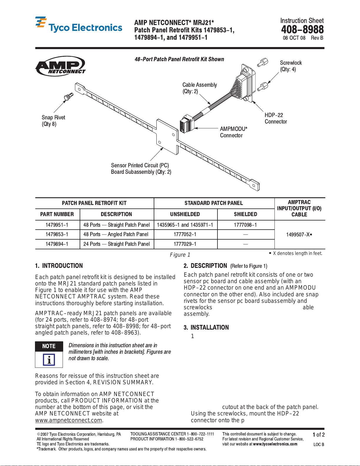
48-Port Patch Panel Retrofit Kit Shown
#)7+<25)1
!9=
'(2+ 88+3(2=
!9=
#4'6 "/;+9
!9=
#+4857 7/49+* /7):/9
5'7* #:('88+3(2= !9=
%
544+)957
544+)957
ATCH ANEL RETROFIT KIT STANDARD ATCH ANEL AM TRAC
ART NUMBER DESCRI TION UNSHIELDED SHIELDED
CABLE
5798 ? #97'/-.9 '9). '4+2 '4*
5798 ? 4-2+* '9). '4+2 ? &
G
5798 ? #97'/-.9 '9). '4+2 ?
Figure 1
G
Xdenoteslengthinfeet.
1. INTRODUCTION
Each patch panel retrofit kit is designed to be installed
onto the MRJ21 standard patch panels listed in
Figure 1 to enable it for use with the AMP
NETCONNECT AMPTRAC system. Read these
instructions thoroughly before starting installation.
AMPTRAC–ready MRJ21 patch panels are available
(for 24 ports, refer to 408–8974; for 48–port
straight patch panels, refer to 408–8998; for 48–port
angled patch panels, refer to 408–8963).
Dimensions in this instruction sheet are in
millimeters [with inches in brackets]. Figures are
not drawn to scale.
Reasons for reissue of this instruction sheet are
provided in Section 4, REVISION SUMMARY.
To obtain information on AMP NETCONNECT
products, call PRODUCT INFORMATION at the
number at the bottom of this page, or visit the
AMP NETCONNECT website at
www.ampnetconnect.com.
2. DESCRI TION
"+,+7 95 /-:7+
Each patch panel retrofit kit consists of one or two
sensor pc board and cable assembly (with an
HDP–22 connector on one end and an AMPMODU
connector on the other end). Also included are snap
rivets for the sensor pc board subassembly and
screwlocks for the HDP–22 connector of the cable
assembly.
3. INSTALLATION
1. Remove the lid screws from the base of the
patch panel. Remove the lid.
2. Remove all of the snap rivets and the cover
plate (24–port patch panel) or plates (48–port
patch panel) from the front of the patch panel.
Also, for the shielded patch panel, remove the
cover plate from the back of the patch panel.
See Figure 2.
3. Place the cable assembly inside the base of the
patch panel, and position the HDP–22 connector
through the cutout at the back of the patch panel.
Using the screwlocks, mount the HDP–22
connector onto the patch panel. See Figure 3.
NOTE
i


